Tube Amplifier Startup Procedure
By Rob Robinette
Have comments or corrections? Email rob at: robinette at comcast dot net
Powering up a new, modified or heavily repaired amplifier is always exciting but using the following procedure can minimize damage to the amp from a wiring mistake and help with fault identification.
WARNING: A tube amplifier chassis contains lethal high voltage even when unplugged--sometimes over 700 volts AC and 500 volts DC. If you have not been trained to work with high voltage then have an amp technician service your amp. Never touch the amplifier chassis with one hand while probing with the other hand because a lethal shock can run between your arms through your heart. Use just one hand when working on a powered amp. See more tube amplifier safety info here.
For newly built or highly modified amp I highly recommend going through the entire amp with a printed copy of the layout and highlight every wire and component as you check them. Taking this last step can save you from hours of frustration as you try to locate a problem. It is very common for new amps to have unsoldered joints or missing wires or even components. Incorrect value resistors are also common and can create very difficult to diagnose symptoms. I recommend you use a color chart and verify the value of every resistor in the amp before first startup.
Safety Ground
Before adding power to a new amp be sure and verify the safety ground connection. Plug a guitar cable into an input jack and check that you have continuity (meter "beep") between the guitar cable's sleeve (the part that isn't the tip) and the amp's power cord ground prong. In the USA it looks like this:
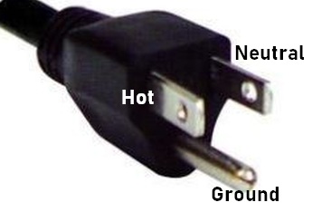
Verify you have continuity between the amp's power cord ground prong and guitar cable and speaker cable sleeve.
If your amp has a main speaker jack, plug a cable in and test again for continuity between the cable sleeve and power cord ground prong. If your amp has speaker wires one or both of them should show continuity with the power cord ground prong.
You must not power up the amp until you have safety ground continuity between the power cord ground prong, guitar cable sleeve, speaker cable sleeve and chassis because the amp is a deadly shock hazard without it. If you don't have continuity use your meter's continuity function to verify your power cord wiring: Hot to the fuse, Neutral to the power transformer primary and the ground prong wire bolted directly to the chassis.
Cap & Diode Polarity
Also before adding power be sure and verify the filter caps are connected - to ground. If your amp has a fixed bias circuit make sure its bias filter cap(s) are connected + to ground because they deal with negative voltage. Getting any of this wrong can lead to exploding capacitors and damaged transformers.
Capacitor Polarity
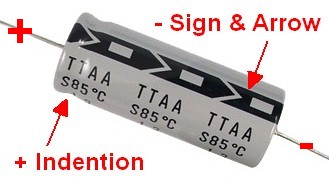
Note the cap's case indentation on the + end of the cap and the arrow pointing to the - end.
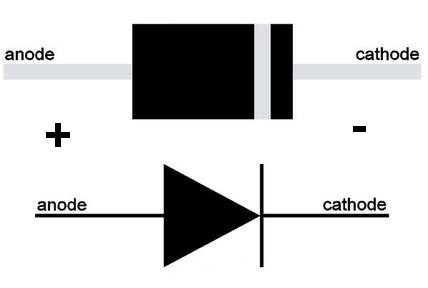
If your amp has any diodes installed, such as a solid state rectifier or fixed bias circuit, make sure their polarity is correct--the striped end of the diode is the cathode.
Solid State Diode Polarity
Startup Tools
For first startup I always use a variac which allows me to slowly bring up voltage to the amp as the new electrolytic caps form. This isn't necessary but if you have a variac you should use it for first startup.
$64 Variac
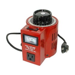
Available here.
I also use a light bulb current limiter to keep an accidental short in the amp from pulling too much current and blowing a fuse or possibly doing damage to the expensive transformers. The limiter's light bulb will initially glow pretty bright when the amp is first powered up but then it will dim once stabilized.
If the light bulb glows near its rated brightness there is a short somewhere in the amp.
If possible you should plug in a functioning amp to see how the light bulb lights with a normal, problem free amp. See my short video for how the light bulb will behave with a normal amp: Youtube Light Bulb Limiter. Following the startup procedure below will help you locate a short.
Simple Light Bulb Current Limiter
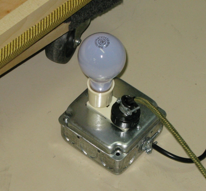
See this to build a light bulb limiter.
A variac and/or light bulb limiter will make the initial startup safer than starting the amp connected directly to wall power.
If you don't use a light bulb limiter then a blown fuse, smoke or arcing will let you know there is a problem during each of the following steps.
If you use both a variac and light bulb limiter then plug the amp into the limiter and plug the limiter into the variac.
Warning: If you must do any repair work inside the amplifier chassis you must measure the DC voltage across the big filter capacitors and don't proceed until the voltage is below 30 volts. If there is more than 30 volts across the caps then you must drain the filter capacitors. This is especially true when you power up the amp without the power tubes in place because the tubes will not use up the power stored in the caps.
Amp Startup Procedure
If you find an amp fault during the startup procedure and this page does not suggest a solution see the Amplifier Troubleshooting page for more information.
Tube socket pin numbers listed below are for an amp using 12A*7 preamp tubes and 8 pin power tubes such as the 6V6, 6L6 and EL34. For other tube types see their tube datasheet for pin outs.
Make sure the amplifier is unplugged.
Remove all tubes from the amplifier.
Place the amp's Standby switch in "Standby" (switch open) if it has one.
Place the amp's Power switch to "OFF."
Put on some safety glasses. If a big filter capacitor is miswired it may explode when power is added (especially if you are not using a variac and/or a light bulb limiter).
If using a variac turn it up to normal wall voltage (120v USA) and turn its switch ON.
If using a variac and light bulb current limiter plug the limiter into the variac.
Voltage Reading Safety
Use volt meter probe clips to keep from sticking your hands into a hot chassis. Power the amp down to move the probes. At the very least use a clip on the ground probe chassis connection so you can probe with the meter's red probe with one hand. Place the extra hand in a pocket (I'm serious here) to prevent a shock from one hand to the other. If one hand touches the amp chassis (which is grounded) and the other hand touches high voltage the current will flow through your chest.
Voltage Reading When Using a Light Bulb Current Limiter
The light bulb current limiter will lower all amp voltages and if you play the guitar amp it will sound funky--this is normal. When this startup procedure calls for the light bulb limiter to be removed then remove it and voltages should be + or - 20% of your amp schematic voltage values.
1. Plug in the Amp
2. If your amp has a solid state rectifier and no standby switch proceed to Step 4, otherwise turn the Amp Power Switch to "On"
Be prepared to immediately turn the amp off and watch for arcing and smoke.
If you are using a light bulb current limiter when you turn the power switch on the limiter light bulb will initially glow as the power transformer comes up to voltage and then dim because without the tubes in place no current is being used. If you are using a high wattage light bulb you may not even see the bulb glow. If the bulb burns near its rated brightness then there is a short in the power cord, power transformer or their connections.
Carefully measure the AC voltage on all of the power transformer connections.
With no tubes installed and no load, all the following voltages may be higher than specified on your amp's schematic or layout.
You should have wall voltage at the fuse and power switch (red meter probe on the fuse or power switch and the black probe on the chassis).
You should have around 5 volts AC on the rectifier tube heater wires (measure wire-to-wire, not wire to ground).
You should have around 6.3 volts AC on the preamp and power tube heaters. On the preamp tubes measure pin 4 to pin 9 and pin 5 to pin 9 across each preamp tube socket and pin 2 to pin 7 on the power tube sockets to make sure every tube socket has heater voltage.
The 6.3v pilot light should light up. If it doesn't the bulb may be burned out or there is no 6.3v AC at the bulb socket terminals.
You should have high voltage AC at the rectifier input (tube or solid state rectifier). I recommend you measure the high voltage wire to ground (not wire-to-wire) on both power transformer high voltage secondary wires because measuring wire-to-wire can expose the meter to over 700 volts AC RMS. If your power transformer is rated at 325-0-325v it means you should have around 325 volts AC from each wire to ground but 650 volts wire-to-wire.
If AC voltage is missing from any of these spots there is a problem with the power transformer or its wiring. See Power Transformer Troubleshooting.
If you are using a variac and your amp has a Standby Switch, turn the variac voltage back down to 0 and proceed to Step 3.
3. Turn the Standby Switch On.
If your amp has a solid state rectifier proceed to step 4. If your amp has a tube rectifier proceed to step 5.
4. Solid State Rectifier: If your amplifier has a solid state rectifier then the filter capacitors will receive DC power and charge up. The entire amp will receive DC power so watch carefully for sparks and smoke.
If you are using a light bulb limiter with no variac you should start with a low wattage bulb like 15 watts. This will slow the rate at which your new filter caps will charge and will help form them for longevity. When you turn the Standby switch ON the bulb will initially glow bright as the filter capacitors charge then the bulb will dim. If it does not dim after a few seconds then there is a short in the amp somewhere downstream of the standby switch. Proceed to step 6.
Form the Filter Caps With a Variac & Solid State Rectifier: If using a variac you want to slowly bring up the amp's voltage to gently form the electrolytic capacitors. Bring the voltage up from 0 volts to 10 volts and monitor the amp for smoke or arcing. Leave the variac on 10 volts for a few minutes then bring the voltage up to 20 volts and monitor the amp again. Wait 10 minutes and repeat until you get up to full wall voltage (120v in the USA). Doing this will allow the new electrolytic capacitors to form in a nice, controlled manner and should help them live a longer life. Turn the amp Power and Standby switches OFF and remove the variac at this time since the filter caps have been formed. If you have a light bulb limiter continue to use it. Proceed to Step 6.
5. Tube Rectifier: If your amplifier has a tube rectifier then install the rectifier tube. With the variac voltage at 0, turn the Power Switch and Standby Switch ON.
The entire amp will receive DC power so watch carefully for sparks and smoke as you add voltage with the variac.
If you have a light bulb limiter but no Variac you should start with a low wattage bulb like 15 watts. This will slow the rate at which your new filter caps will fill and will help form them for longevity.
Form the Filter Caps With a Variac & Tube Rectifier: If using a variac you want to slowly bring up the amp's voltage to form the electrolytic capacitors. Bring the voltage up to 10 volts AC on the variac and monitor the amp for smoke or arcing. Leave the variac on 10 volts for a few minutes then slowly bring the voltage up to 20 volts and monitor the amp again. Wait 10 minutes and repeat until you get up to full wall voltage (120v in the USA). Doing this will allow the new electrolytic capacitors to form in a nice, controlled manner and should help them live a longer life. Turn the amp Power and Standby switches OFF and remove the variac at this time since the filter caps have been formed. If you have a light bulb limiter continue to use it.
If the light bulb stays bright after the Standby Switch is turned On there is a short in the rectifier tube, its wiring, the filter caps, their wiring or the power distribution wires to the circuit board and tube sockets.
If the bulb goes dim then switch your meter to DC Volts and measure voltage at each filter capacitor (these voltages should be the same at each filter cap and be much higher than spec because there is no load on the power supply). With no load the filter capacitors can charge up to the power transformer's AC peak voltage output so you can see up to 700 volts DC on the filter caps.
Measure the DC voltage at the preamp tube plates (pins 1 & 6). The voltage should be about the same as what was measured at the filter capacitors. If you don't find voltage on pins 1 & 6 probe upstream toward the power supply to find where the voltage is disconnected.
Measure the DC voltage where the output transformer connects to the power tube sockets. The voltage should be about the same as what was measured at the filter capacitors.
Turn the Power and Standby Switches OFF and measure the DC voltage on the filter caps to ensure it bleeds down to 30 volts DC or lower. If your amp does not have filter cap bleeder resistors the voltage will stay high so you must drain the filter caps manually. It's best if there is less than 30 volts DC on the tube sockets for the power tube install.
Warning: With no power tubes installed your amp may hold a charge of 700 volts even with the amp unplugged.
When the filter capacitor voltage is below 30 volts DC proceed to Step 6.
6. Install all the preamp tubes (all tubes except the power tubes)
Turn the Power switch ON.
If the light bulb burns near its rated brightness a bad preamp tube or miswired socket is shorting the heater circuit (with Standby switch open only heater voltage should be on the tube socket).
Turn the Standby switch ON.
If the bulb stays bright there is a shorted preamp tube or there is a problem with the preamp wiring. Remove all the preamp tubes except one and try again. If the bulb stays bright replace that tube with another. If the light bulb goes dim then the original tube is bad. Try the good tube in all the sockets. If the bulb remains bright there is a problem with that socket wiring or circuit.
If the light bulb dims with all the preamp tubes installed then measure the voltages at all the preamp pin tubes. Nine pin preamp tubes' pins 4 & 9 and 5 & 9 will have 5.9 to 7v AC heater voltage and the pins 1, 3, 6, 8 will have DC. Normal preamp gain stages should have voltage on their plates and cathodes but not on their grids. Phase inverters will have voltage on their grids. Cathode followers may have high voltage on their plates, grids and cathodes.
Verify all the preamp tubes show yellow heater glow but no red plating or arcing. Dimming the room lights can help see the heater glow, red plating and arcing.
7. If your amp has fixed bias then carefully measure the DC bias voltage at all the power tube grid pins
Amps with fixed bias will show a negative voltage on the power tube grid pins. If the bias voltage is not present at any of the power tube grids inspect the bias circuit.
Grid is pin 5 for 6V6, 6L6 and EL34
Grid is pin 2 for EL84
-30 to -60 volts DC (negative voltage) should be present on all the grid pins.
If your amp has a bias pot, adjust it for the largest negative DC voltage possible (-60v is better than -40v). This will set the coolest, safest power tube bias.
Turn the Power and Standby switches OFF.
8. Connect a speaker and install all the power tubes
You may want to connect an inexpensive speaker to prevent damage to a nice speaker.
Warning: You must connect a speaker or dummy load or you may damage the power transformer.
Turn all the volume and gain controls to full down.
If you are using a light bulb current limiter remember all the amp's voltages will probably be lower than spec. How low depends on the current demand from the amp and the watt rating of the light bulb. If you play a guitar through the amp with the current limiter attached it will sound funky. After a successful startup with all tubes in place you can remove the light bulb limiter, set the bias for fixed bias amps and test the amp's tone with a guitar and measure the amp voltages to compare to known good voltages. If you test the amp's tone with the bias set full cold it may sound cold and sterile.
Turn the Power switch ON.
Note: for a problem free amp the light bulb will glow brighter than the earlier tests because the power tubes use up most of the amp's power, but the bulb should not glow at its full rated brightness.
If the light bulb burns near its rated brightness with the amp on but Standby switch off a bad power tube or miswired socket is causing a heater short.
If the bulb goes dim turn the Standby switch ON.
Be prepared to turn the Standby or Power switch OFF.
If the amp emits a squeal it may be caused by positive feedback in the negative feedback circuit. If your amp has a negative feedback loop and squeals, turn the Power and Standby Switches off, verify less than 30 volts DC at the filter caps (drain the filter caps manually if needed) and swap the output transformer wires on the power tube sockets and start over at Step 8. Swapping the power tube output transformer wires will change the polarity of the negative feedback signal and stop the squeal.
Verify all the power tubes show yellow heater glow but no red plating or arcing. Dimming the room lights can help you see glowing red spots on the plates.
If the bulb goes dim with all the tubes in place then congratulations, you're almost done with the startup.
Test your amp with a speaker and guitar. Keep in mind the amp will sound crappy with the light bulb limiter in place.
Power down the amp and remove the light bulb limiter
If the light bulb limiter stays bright power down the amp and remove one power tube.
[If your amp has only one power tube then replace the tube with another power tube and try again. If the bulb goes dim then the other power tube was bad. If it stays bright there is a problem with the socket, wiring or power amp circuit.]
If the bulb goes dim after removing a power tube the problem is with the empty socket or the tube you removed. Power down the amp and move the power tube in the amp to the other socket.
If the bulb goes dim the other power tube is bad.
If the bulb stays bright the socket, its wiring or its circuit is shorted.
9. With the light bulb limiter removed, turn on the amp and put the Standby switch in "play"
Set the power tube bias and test it again with a guitar. You should also record voltage readings for future reference and to compare with known good voltages.
Carefully measure the DC voltage at all the power tubes' plates and screens
Pin 3 for 6V6, 6L6 and EL34 plate, pin 4 for screen
Pin 7 for EL84 plate, pin 9 for screen
Measure the DC voltage at the preamp tube cathodes (pins 3 & 8). The voltage should be between 1 and 2 volts for gain stages. You will have much higher voltage on a phase inverter or cathode follower tube's cathodes (see 5E3 diagram above, V2 pin 8).
Measure the DC voltage at the preamp tube grids (pins 2 & 7). The voltage should be close to 0 volts for gain stages. You will have much higher voltage on a phase inverter or cathode follower tube grids (see 5E3 diagram above, V2 pin 7).
Compare your voltages to known good voltages. See this for 5F6A Bassman voltages.
Standard 5E3 Deluxe DC Voltages
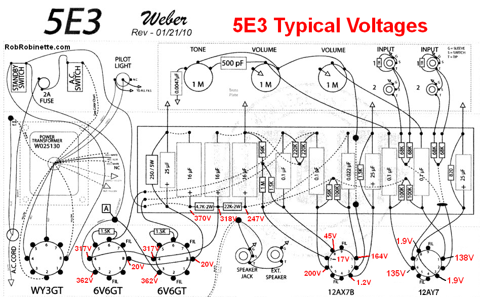
Note the V2B phase inverter (pins 6, 7 & 8) voltages are different than V1A, V1B and V2A gain stages.
Troubleshooting
If you encounter problems with the amp see the Amplifier Troubleshooting page.
By Rob Robinette
References
RCA Corporation, RCA Receiving Tube Manual, RC30.
Merlin Blencowe, Designing Tube Preamps for Guitar and Bass, 2nd Edition.
Merlin Blencowe, Designing High-Fidelity Tube Preamps
Morgan Jones, Valve Amplifiers, 4th Edition.
Richard Kuehnel, Circuit Analysis of a Legendary Tube Amplifier: The Fender Bassman 5F6-A, 3rd Edition.
Richard Kuehnel, Vacuum Tube Circuit Design: Guitar Amplifier Preamps, 2nd Edition.
Richard Kuehnel, Vacuum Tube Circuit Design: Guitar Amplifier Power Amps
Robert C. Megantz, Design and Construction of Tube Guitar Amplifiers
Neumann & Irving, Guitar Amplifier Overdrive, A Visual Tour It's fairly technical but it's the only book written specifically about guitar amplifier overdrive. It includes many graphs to help make the material easier to understand.
T.E. Rutt, Vacuum Tube Triode Nonlinearity as Part of The Electric Guitar Sound