Headphone to Speaker Amp Interface
With Balanced XLR and Switched 1/4" and 1/8" TRS Headphone Jacks and Bypassable Resistor Network
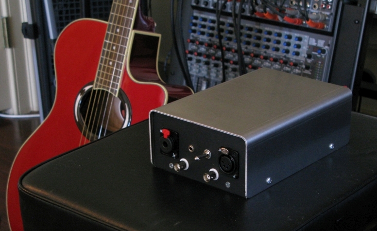
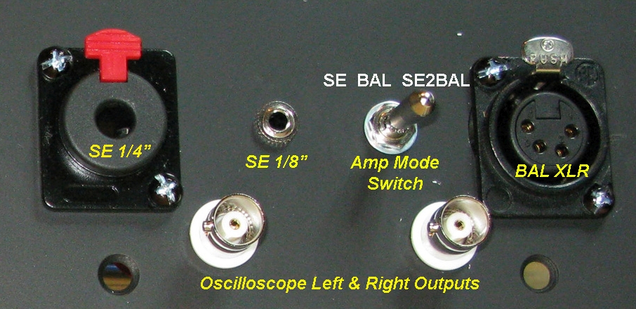
Front panel features balanced 4-Pin XLR, 1/4" & 1/8" headphone jacks, 'Amp Mode Switch' and optional oscilloscope out BNC connectors.
The Robinette Box© is a headphone to speaker amplifier interface which will connect just about any headphone with any amp (tube, solid state, balanced, single-ended). It's designed to electromagically match your headphones to a speaker amplifier's speaker output. Jump down to the Instructions to see how the box operates.
The Robinette Box is open source hardware under the Creative Commons permissive license and is open to royalty-free commercial use. The schematic diagram was created using the free ExpressSCH and the editable schematic file is available here: Robinette Box schematic. The layout diagrams were created using the free DIYLC (DIY Layout Creator) and the editable layout file is here: Robinette Box V3 Layout.
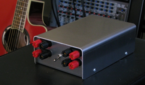
Rear panel's speaker binding posts and 'Network Bypass Switch'
Headphones and 'Amp Mode Switch' on left, speaker binding posts and 'Network Bypass Switch' on right.
Connecting headphones directly to a speaker amplifier's speaker outputs can cause three problems:
1. Headphone impedance tends to run 4 to 75 times higher than speakers. This impedance mismatch can cause problems, especially for tube amplifiers. The Robinette Box's resistor network will give your speaker amp 7.9 ohms of effective speaker load (an almost perfect 8 ohms) no matter the impedance of your headphones, even with three sets of headphones used simultaneously.
2. Excessive gain. Speaker amplifiers are made to move large amounts of air using big speakers. Connect them to tiny sensitive headphones and the amp's noise floor may be audible as a hiss. The resistor network will attenuate the amp's output by over 12 dB (decibels) which will lower the noise floor and greatly reduce audible hiss.
3. Lack of usable volume control. You may find you can only turn your speaker amp's volume control 20 or 30% before you get to your headphone's max listening level. The resistor network's 12 dB of attenuation will give you more usable volume knob movement allowing more precise volume setting.
The Robinette Box is connected to the amplifier's speaker outputs using four 'IN' 5-way speaker binding posts (accepts single and dual banana plugs, spades and raw wire up to 10 gauge). You can connect your speaker cables to the 'OUT' speaker posts. With your speakers connected and the 'Network Bypass Switch' in 'Bypass' your speakers will receive a completely unmodified signal. Your headphones are plugged into the other side of the box using a balanced 4-Pin XLR and single-ended 1/4" (6.3mm) and 1/8" (3.5mm) TRS jacks. The TRS jacks are your 'normal' headphone jacks. You will have to manually disconnect your speakers to keep them from playing when using headphones but you won't have to get access to the back of your amp to do it. If you don't want the extra binding posts you can simply delete them from your build. The resistor network is passive so battery power or plugs are not required.
If you're an electronics experimenter one option you may want to consider is the addition of a pair of left and right BNC connectors tapped into the XLR connector. This allows easy, direct connection to an oscilloscope to analyze the signal being sent to the headphones.
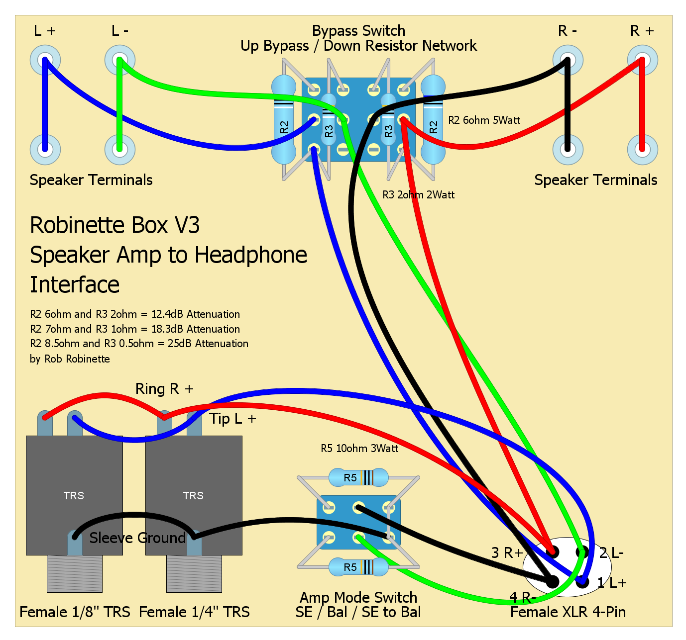
Robinette Box V3 Schematic
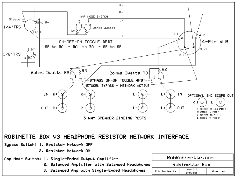
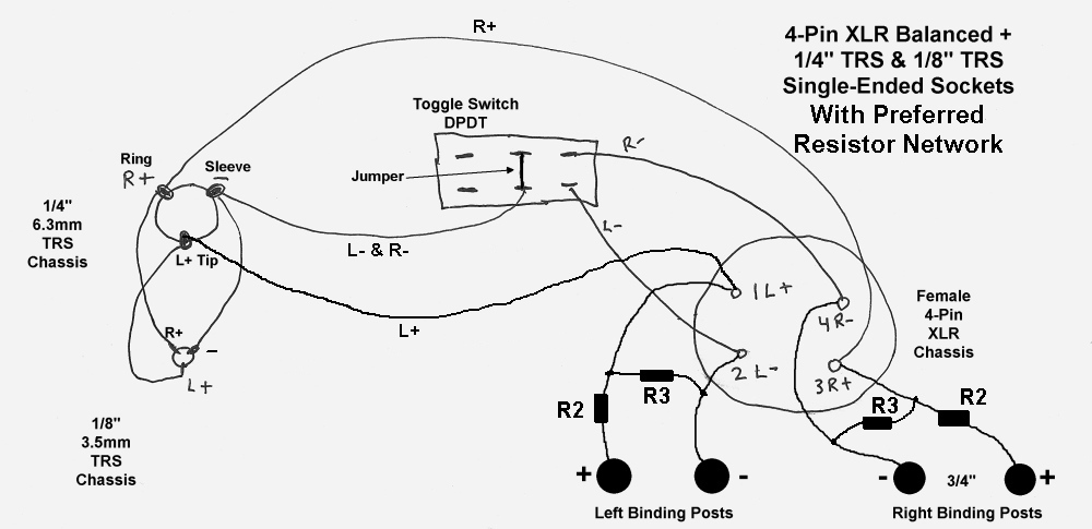
Resistor Network Bypass Switch is located near the Speaker Binding Posts and is shown in the "Network Active" position. The Amp Mode Switch is shown in the "Single-Ended Headphones to Single-Ended Amp" position with all three headphone jacks usable. Download the Robinette Box V3 ExpressSCH schematic file here and tweak the design to your exact needs.
Robinette Box V3 Layout Diagram
Click the image to download the editable DIYLC (DIY Layout Creator) file.
Version 3 of the Robinette Box adds a Network Bypass Switch. When connected to an amp that doesn't need speaker load impedance matching or attenuation (many small solid state amps) you can bypass the resistor network to send an unaltered audio signal to your headphones. You can also do A/B testing to see if your amplifier sounds best with or without the resistor network active.
The two positions of the Network Bypass Switch are:
Switch Up = Network Bypass. XLR and TRS connectors are directly connected to the speaker binding posts.
Switch Down = Resistor Network Active. "Preferred Resistor Network" is switched into the circuit.
Network Bypass 4PDT Toggle Switch With Latching Lever
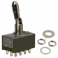
The latching lever prevents accidental switch changes.
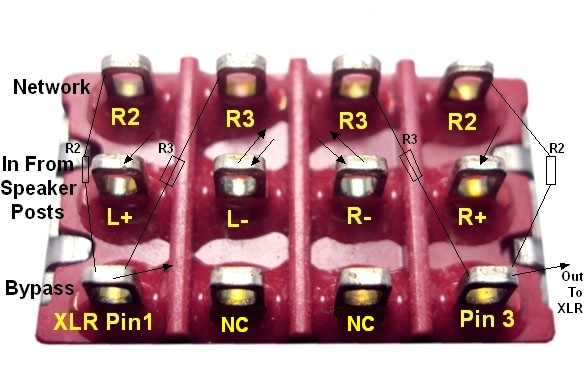
Signal from speaker posts comes in to switch's center terminals. Switch Up = center and lower terminals are connected = Resistor Network Bypass. Switch Down = center and upper terminals are connected = Resistor Network Active. L- and R- center terminals are connected to the speaker posts and the XLR connector. NC=No Connection.
A three position ON-OFF-ON DPDT toggle switch is used to switch between amplifiers with single-ended output and amps with balanced output. The switch only needs to be changed when moving the Robinette Box to a new amplifier.
The three Amplifier Mode Switch positions are:
1. Single-Ended Output Amplifier. Switch lever toward TRS headphone jacks. Use this position for amplifiers with single-ended output (common ground). All three headphone jacks are active.
WARNING: Only use this switch position when connected to an amplifier that has its black speaker terminals tied together (common ground or single-ended). Selecting this position while connected to an amp with balanced output can damage your headphones and amplifier. This switch uses a latching lever to prevent accidental selection of this position. You can verify the amp's black speaker terminals are tied together by using a multimeter's continuity test. With the amp unplugged touch the multimeter's probes to the black speaker terminals. If you get the continuity beep your black speaker terminals are tied together and it's safe to use the single-ended amp switch position. If you do not get continuity your amp has balanced output and you should not engage this mode. Your amp's schematic diagram will also show a ground symbol connected to the black speaker posts. More info on balanced versus single-ended amplifier output can be found here.
2. Balanced Output Amplifier with Balanced Headphones. Switch lever centered. Use this for amplifiers with balanced output (non-common ground). Only the XLR jack is active. The TRS headphone jacks' combined ground is disconnected to protect the amplifier.
3. Balanced Output Amp with Single-Ended Headphones. Switch lever toward XLR jack. Use this position when you need to use single-ended headphones with an amplifier that has balanced output. The balanced amplifier is protected from the TRS jacks' combined ground by resistors R5. All three headphone jacks are active.
Amp Mode Switch ON-OFF-ON DPDT Terminals
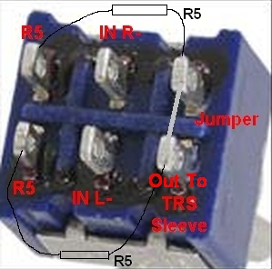
Note the jumper connecting the rightmost terminals and the connections for the R5 resistors.
You can use the XLR and both TRS jacks simultaneously in either of the single-ended modes. The jacks are wired in parallel so the total circuit impedance will drop. The formula to determine what the impedance drops to is:
2 Headphones Used Simultaneously 3 Headphones Used Simultaneously
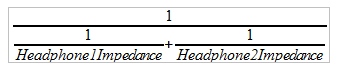
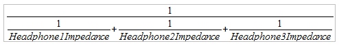
With two 32 ohm headphones total impedance = 16 ohms. With three impedance = 10.7 ohms
With the resistor network active the impedance drop from using multiple headphones will not have an appreciable effect on the amp or sound quality.
The Robinette Box uses an L-pad attenuation circuit to lower the amplifier's output to your headphones. The resistor values I use will work great with pretty much any amp and headphone combo. With an R2 value of 6 ohms and R3 of 2ohms you get 12.4 decibels of attenuation and an effective speaker load of 7.9 ohms. I call this setup the "Preferred Resistor Network" because of its popularity.
If your speaker amp needs 4 ohms of speaker load then use an R2 of 3 ohms and an R3 of 1 ohm to get 4 ohms of effective speaker load and 12.4 dB of attenuation. For an amp that needs 16 ohms of speaker load use 12 ohms and 4 ohms to get 16 ohms of effective speaker load.
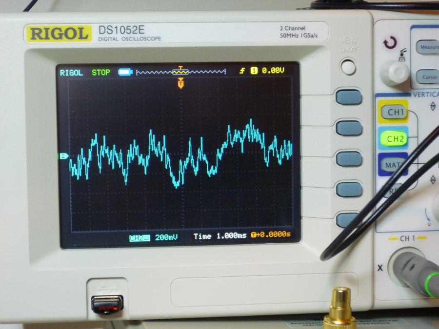
Audio with resistor network and 12.4dB of attenuation.
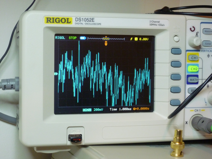
Audio with 'Network Bypass' in bypass position and no attenuation.
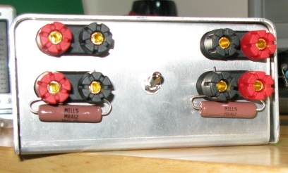
Speaker posts and 'Network Bypass Switch' in bypass. Optional external 10 ohm 10 watt wirewound resistors in place for tube amp that needs 8 ohms of effective speaker load but no attenuation.
With my 45 watt per channel tube amplifier this attenuation circuit moved my maximum listening volume from 9 o'clock to 11:30. If you're running a 100+ watt per channel amp you may want to go with R2 of 7 ohms and R3 of 1 for 18.3 dB of attenuation and the same 7.9 ohms of speaker load. If you'd like to try to perfect the match of your headphones to your amp you can tune the resistor values using my Headphone Resistor Network Calculator webpage or download my much more detailed and complex Headphone Resistor Network Calculator Spreadsheet. I also have a free Android app, the Headphone Calculator for Android available in the Google Play Store or direct download here: Headphone Calculator for Android It does both network and power calculations.
Building the Robinette Box
All of this will fit in a 4" x 5" x 2" project box but a larger box will be easier to work with. Put four 5-way speaker binding posts and the and ON-ON 4PDT (4 Pole, Dual Throw) Toggle Switch on one long side of the box (use 3/4" spacing between binding posts for dual-banana plug compatibility). Red binding posts are +, black are -. I used four pair of dual banana binding posts. The connecting wire between the IN and OUT binding posts should match the gauge of your speaker wire. Putting the toggle switch between the left and right binding posts will keep the wiring as short as possible.
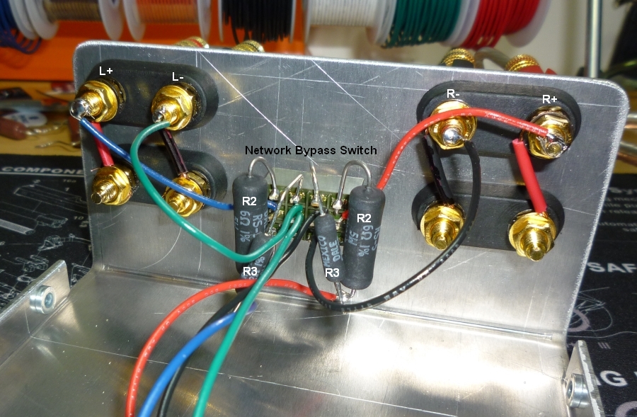
Speaker binding posts and 'Network Bypass Switch.'

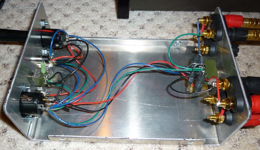
'Network Bypass Switch' with resistor network. Large resistors are R2, small resistors are R3.
Put the Female 4-Pin XLR, 1/4" and 1/8" TRS panel mount headphone jacks and the ON-OFF-ON DPDT (Dual Pole, Dual Throw) toggle switch on the other long side of the box. It's easier to solder the switches if you do what you can before installing the switches in the box. You can also mount all the pairs of resistors directly to the switches before installing the swtches. I used a step-drill bit to drill the big hole for the XLR and 1/4" TRS jacks.
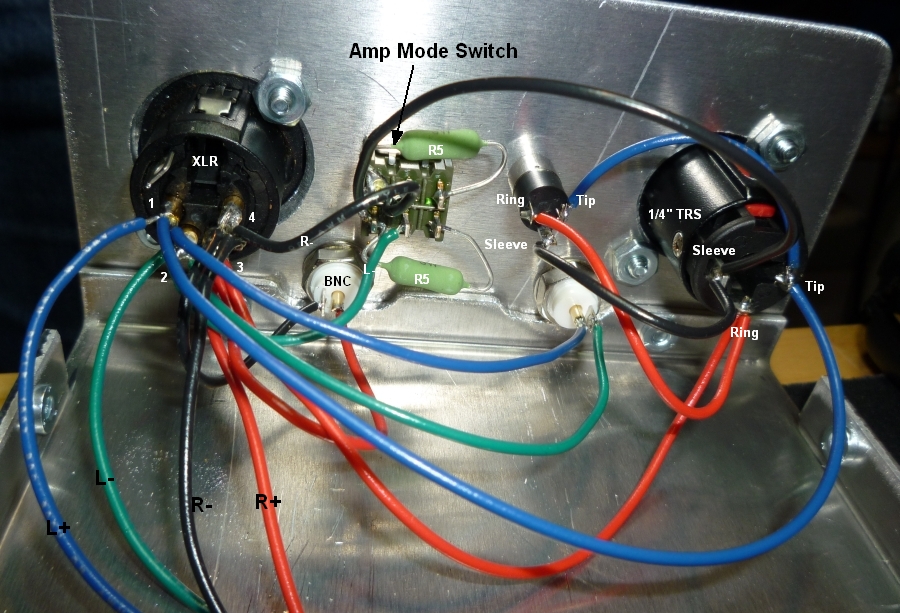
Headphone jacks (XLR on left), 'Amp Mode Switch' in center and Oscilloscope output BNC jacks at bottom.
18, 20 or 22 gauge wire is recommended for the internal wiring. Keep in mind that Canare's beefy Star Quad cable uses only 21 gauge wire and most headphone cables use 24 or 26 gauge so thick wire isn't needed and it's harder to work with, especially when soldering the toggle switches. I went with 22 gauge wire because that's what I had on hand. If I was going to order new wire I would have gone with 20 gauge.
Suggested Wire Color Code
Red R+
Black R-
Blue L+
Green L-
You can make the jumper connection between the Amplifier Mode toggle switch's terminals by extending one resistor leg through one terminal over to the other then solder both terminals.
4-Pin Female XLR Connector
Pin 1 Blue wire L+
Pin 2 Green wire L-
Pin 3 Red wire R+
Pin 4 Black wire R-
TRS Connectors
Tip Blue wire L+
Ring Red wire R+
Sleeve Black wire Combined L- and R-
I made a set of 3 feet long speaker patch cables using 14 gauge speaker wire and banana plugs to connect the amp to the interface box but 16 or 18 gauge wire would work well too.
Testing
Be sure and test your finished box using a multimeter before trying it with an amplifier.
Start with the Network Bypass switch up in the 'Bypass' position and the Amp Mode switch in the center 'Balanced Amp' position.
Test for continuity (shorts) between the 4 speaker posts. You should have open circuits (no connection) with no continuity. Test that you do have continuity between the XLR connector and speaker posts. XLR pin 1 to L+, 2 to L-, 3 to R+, 4 to R-. The pin numbers are molded into the XLR connector. I stick a paper clip into the XLR pin holes for this test.
Move the Amp Mode switch to the left (toward the XLR connector) to the 'Single-Ended Headphones to Balanced Amp' position. You should read approximately 20 ohms of resistance between the black speaker terminals. The 20 ohm reading is the two R5 10 ohm resistors in series.
Move the Amp Mode switch to the right (toward the TRS connectors) to the 'Single-Ended Headphones to Single-Ended Amp' position. The black speaker terminals should show continuity between them because they are now tied together.
Move the Network Bypass switch down to the 'Network Active' position. You should now see approximately 8 ohms of resistance between the R+ and R-, and between L+ and L- speaker posts. You should see approximately 2 ohms between XLR pins 1 & 2, and 3 & 4. This reading is R3.
Always make sure the Amp Mode switch is set correctly for your amp. You will only have to change this switch when you change amplifiers but remember to heed this:
WARNING: Only use the 'Single Ended Amplifier' switch position when connected to an amplifier that has its black speaker terminals tied together (common ground or single-ended). Selecting this position while connected to an amplifier with balanced output can damage your headphones and amplifier. I used a toggle switch with a latching lever to prevent accidental selection of this position. You can verify the amp's black speaker terminals are tied together by using a multimeter's continuity function. With the amp unplugged touch the multimeter's probes to the black speaker terminals. If you get the continuity beep your black speaker terminals are tied together and it's safe to use the single-ended amp switch position. If you do not get continuity your amp has balanced output and you should not engage this mode. More info on balanced versus single-ended amplifier output can be found here.
Testing 'Amp Mode Switch' with single-ended headphones and balanced output amplifier.
Listening Tests
I spent hours listening to a wide variety of music through the Robinette Box to evaluate it and look for areas to improve. I used it with three A/V receivers, a 45 watt tube amplifier and a variety of Class T Tripath balanced output amplifiers. I listened with several sets of headphones including HiFiMAN HE-500s, AKG K240 Studios and modified Fostex T50RPs. I listened with the headphones connected directly to the speaker outputs and compared that to the Robinette Box with the resistor network switched in and out. I listened to all three headphones connected to the balanced 4-pin XLR as well as using a single-ended adapter so I could sample all three headphones using the 1/4 inch and 1/8" single-ended headphone jacks.
When connected to amplifiers with single-ended (common ground) output I compared the sound quality with and without the R5 ground protection resistors in the circuit.
After all of the testing I can honestly say I cannot tell the difference between any of the above configurations. In fact many times I would begin to form opinions on how the resistors were affecting the sound quality and then realize the resistor network or ground protection resistors were switched out of the circuit. I'm convinced that most people would not be able to tell the difference in any of the configurations in a true blind listening test.
The Robinette Box offers the ultimate in flexibility for interfacing your headphones to speaker amplifiers while delivering uncolored sound quality to your ears.
Instructions
WARNING: You must set the Amplifier Mode Switch before connecting your amplifier to the Robinette Box. An incorrect switch setting can damage a balanced output amplifier and your headphones.
Before connecting the Robinette Box to an amplifier set the Amplifier Mode Switch' to match the amplifier you are connecting to. The switch is used to switch between amplifiers with single-ended output and amps with balanced output. The switch only needs to be changed when moving the Robinette Box to a new amplifier. The switch has a latching lever to prevent accidental movement so the lever must be pulled outward slightly to change switch positions.
Set the Amplifier Mode Switch
1. Single-Ended Output Amplifier. Switch lever toward TRS headphone jacks. Use this position for amplifiers with single-ended output (common ground). All three headphone jacks are active.
WARNING: Only use this switch position when connected to an amplifier that has its black speaker terminals tied together (common ground or single-ended). Selecting this position while connected to an amp with balanced output can damage your headphones and amplifier. You can verify the amp's black speaker terminals are tied together by using a multimeter's continuity test. With the amp unplugged touch the multimeter's probes to the black speaker terminals. If you get the continuity beep your black speaker terminals are tied together and it's safe to use the single-ended amp switch position. If you do not get continuity your amp has balanced output and you should not engage this mode. Your amp's schematic diagram will also show a ground symbol connected to the black speaker posts. More info on balanced versus single-ended amplifier output can be found here.
2. Balanced Output Amplifier with Balanced Headphones. Switch lever centered. Use this for amplifiers with balanced output (non-common ground). Only the XLR jack is active. The TRS headphone jacks' combined ground is disconnected to protect the amplifier.
3. Balanced Output Amplifier with Single-Ended Headphones. Switch lever toward XLR jack. Use this position when you need to use single-ended headphones with an amplifier that has balanced output. The balanced amplifier is protected from the TRS jacks' combined ground by resistors R5. All three headphone jacks are active.
Set the Network Bypass Switch to the Down position (resistor network active)
Switch Up = Network Bypass. XLR and TRS connectors are directly connected to the speaker binding posts.
Switch Down = Resistor Network Active. Attenuation L-pad 'Preferred Resistor Network' is switched into the circuit.
WARNING: The headphone volume will jump by 12.4 decibels when the Network Bypass Switch is moved to the Bypass position. Turn the amplifier volume down before selecting the Bypass position.
Note: With the Network Bypass Switch down (network active) it is safe to run your amplifier with no headphones connected because the amplifier will be given an 8 ohm load by the resistor network.
Connect the Robinette Box to your amplifier
With the Amplifier Mode Switch set properly connect the box to your amplifier's speaker terminals. The Robinette Box speaker binding posts will accept single and dual banana plugs, spades and raw wire up to 10 gauge. When viewing the box from the front (the end with headphone jacks) the right speaker posts are on the right and the left are on the left. The upper binding posts are for the amplifier connection, the lower binding posts are optionally used to connect your speakers.
Connect your headphones to the Robinette Box
Turn your amplifier volume full down then power it up
Turn the volume up slowly to keep from overpowering and possibly damaging your headphones. Remember to turn the amplifier volume down before changing position of the Network Bypass Switch.
Enjoy your headphones and speaker amp
Parts List
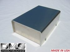
Project Box 5" x 5" x 2" or larger (MCM). ebay also has some inexpensive but nice aluminum project boxes--search ebay for "aluminum project box." Plastic is easier to drill but metal will shield the box from external electronic noise. I used this 5" x 8" x 2.5" aluminum box from Dynamic Metal Shop on ebay but their 5" x 5" x 2.5" would be better.
Four or Eight 5-way Speaker Binding Posts (eBay, about $2 each) You'll need 8 if you add the speaker out binding posts. I used 4 pair of dual banana connectors.
18, 20 or 22 gauge wire
Vishay/Dale wirewound non-inductive 1% tollerance resistors about $2 each.
2 each Resistor2 Mouser part# 71-RS0056R000FB12 Vishay part# RS0056R000FB12 5watts 6ohms 1%
2 each Resistor3 Mouser part# 71-NS2B-2 Vishay part# NS02B2R000FB12 3watts 2ohms 1%
2 each Resistor5 Mouser part# 594-AC03W10R00J Vishay part# AC03000001009JAC00 3watts 10ohms 5%
Female 4-Pin XLR Panel Mount about $5 (recommend Neutrik from ebay)
ON-ON SWITCH TOGGLE 4PDT 6A 125V by NKK Digi-Key part# 360-1871-ND $12 (4 Pole, Dual Throw) for Network Bypass switch (NKK are high quality--don't cheap out on the toggle switches)
ON-OFF-ON SWITCH TOGGLE DPDT 6A 125V by NKK Digi-Key part# 360-1849-ND $7 (Dual Pole, Dual Throw) for Amp Mode switch.
1/4" 6.3mm Stereo TRS Panel Mount $5 (recommend Neutrik female, non-switching, non-grounding from ebay)
1/8" 3.5mm Stereo TRS Panel Mount $4 (recommend Neutrik female, non-switching, non-grounding from ebay)
Optional Insulated BNC Panel Mounts (2 each at $4 ebay) for the oscilloscope connection. You will need insulated panel mounts if you use a metal project box. I am planning to add a second set of BNC connectors to feed the input from the speaker posts to an oscilloscope so I will have easy access to the box's input and output signals.
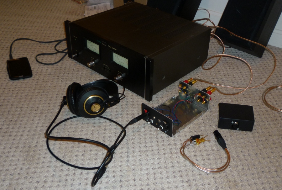
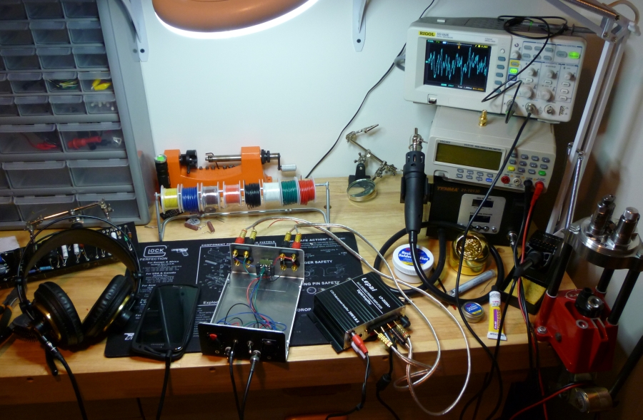
Testing the Robinette Box with my 1978 Sansui BA-2000 amp.
Other Configurations of the Box
Robinette Box Version 2
Version 2 of the interface is less complex and does not have the resistor network bypass switch.
The three Amplifier Mode Switch positions are the same as V3:
1. Single-Ended Headphones to Single-Ended Amplifier. All three headphone jacks are active.
WARNING: Only use the "Single-Ended Headphones to Single Ended Amplifiers" switch position when connected to an amplifier that has its black speaker terminals tied together. Selecting this position while connected to a balanced amp can damage your headphones and amplifier. I used a toggle switch with a latching lever to prevent accidental selection of this position. You can verify the amp's black speaker terminals are tied together by using a multimeter's continuity function. With the amp unplugged touch the multimeter's probes to the black speaker terminals. If you get the continuity beep your black speaker terminals are tied together and it's safe to use the TRS single-ended switch position.
2. Balanced Headphones to Balanced Amplifier. Only the XLR jack is active. The TRS combined ground is disconnected.
3. Single-Ended Headphones to Balanced Amp. Amplifier is protected from the TRS combined ground by resistors R5 and all three headphone jacks are active.
Robinette Box V2 Schematic
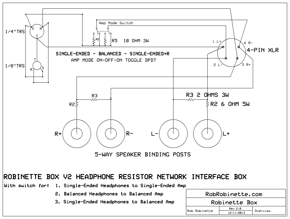
Note three position ON-OFF-ON DPDT Toggle Switch. Download the Robinette Box V2 ExpressSCH schematic file here.
Robinette Box With Bypass Switch and Simple TRS Disconnect Switch
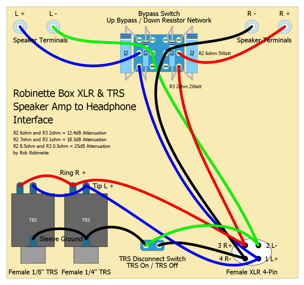
TRS Disconnect switch (ON/OFF SPST) disables the TRS jacks by separating the TRS grounds for use with balanced output amps. This adapter will work with single-ended and balanced output speaker amplifiers. Click the image to download the editable DIYLC file.
Robinette Box with Only 4-Pin XLR Output
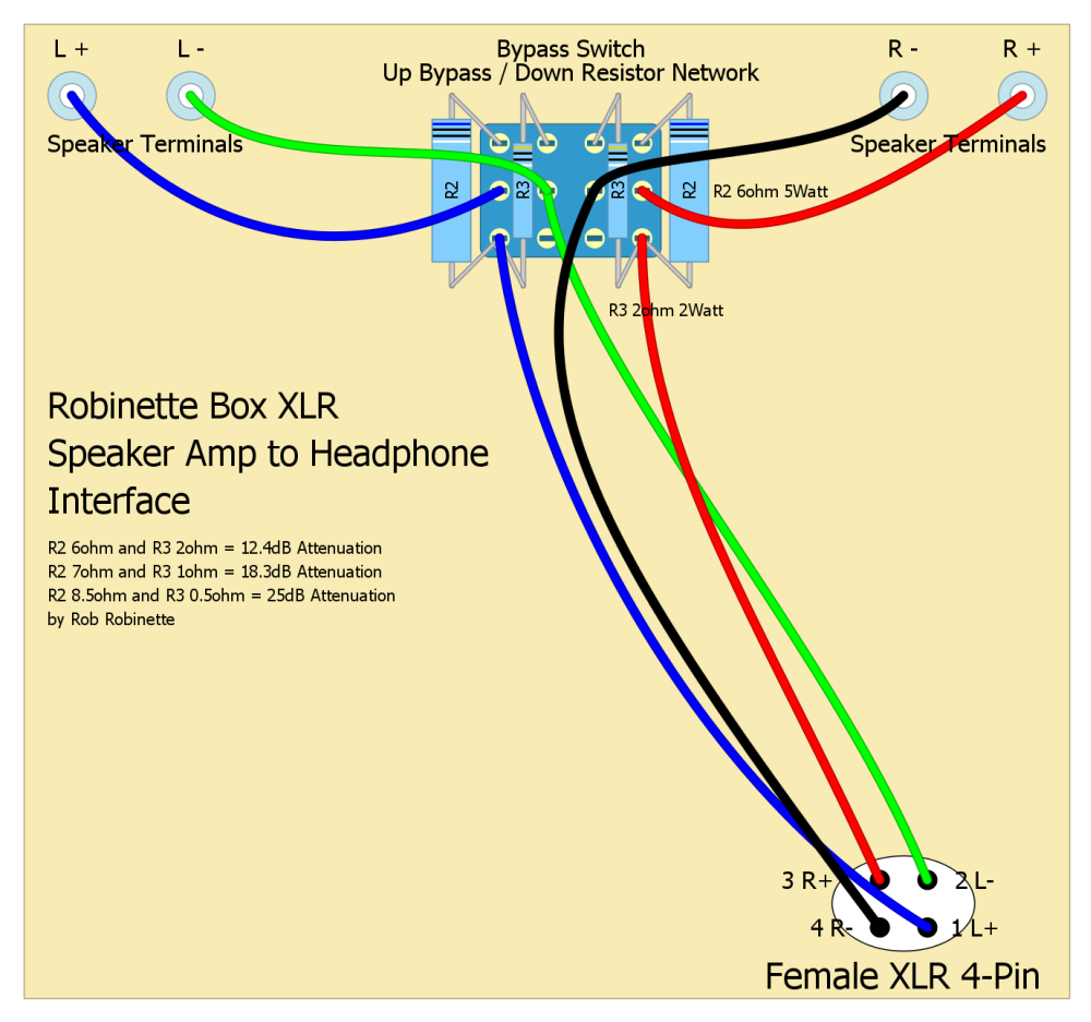
This adapter will work with single-ended and balanced output speaker amplifiers. Click the image to download the editable DIYLC file.
Robinette Box with Only TRS Output
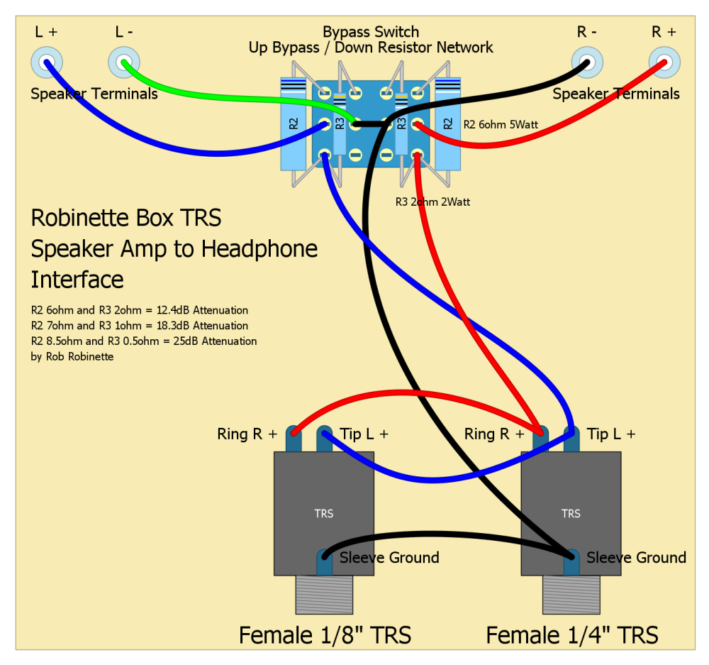
This type of adapter is only for amplifiers that have their negative speaker terminals tied together (common ground). Click the image to download the editable DIYLC file.
Robinette Box Version 1
This is my original design. The main differences are it has no network cutout switch and uses a two-way toggle switch with just two positions:
1. Single-Ended Headphones to Single-Ended Amplifier. All three headphone jacks are active.
WARNING: Only use the "Single-Ended Headphones to Single Ended Amplifiers" switch position when connected to an amplifier that has its black speaker terminals tied together. Selecting this position while connected to a balanced amp can damage your headphones and amplifier. I used a toggle switch with a latching lever to prevent accidental selection of this position. You can verify the amp's black speaker terminals are tied together by using a multimeter's continuity function. With the amp unplugged touch the multimeter's probes to the black speaker terminals. If you get the continuity beep your black speaker terminals are tied together and it's safe to use the TRS single-ended switch position.
2. Balanced Headphones to Balanced Amplifier. Only the XLR jack is active. The TRS combined ground is disconnected.
The Original V1 Robinette Box With Two Position Mode Switch
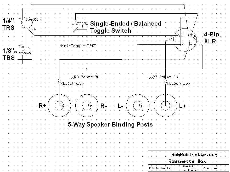
V1 Box Detail
Note two position ON-ON DPDT Toggle Switch. Switch lever toward XLR jack = Balanced Amplifier Operation and only the XLR jack is active. Lever toward TRS jacks = Single-Ended Amplifier Operation with all three jacks useable. Note how the R- and L- are combined at the toggle switch with a jumper between the switch's center terminals. Download the Robinette Box V1 ExpressSCH schematic file here.
Basic Speaker Amp to Headphone Adapter Box Attenuator
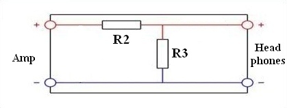
"Preferred Resistor Network" used in the Robinette Box supplies amplifier load and attenuation. Resistor R2 is 6 ohms and 5 watts. Resistor R3 is 2 ohms and 3 watts. See the Headphone Resistor Network Calculator webpage to optimize the resistor values for your headphones and your amplifier.
Basic Speaker Amp to Headphone Adapter - Single Ended TRS
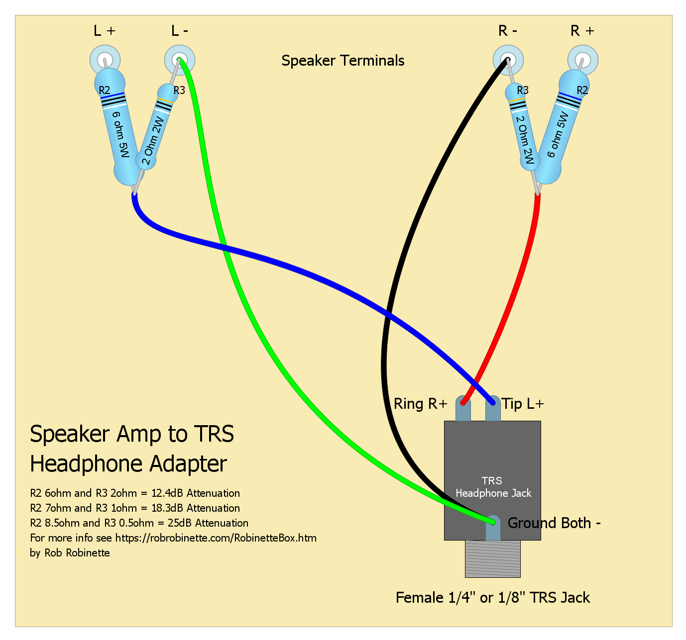
This type of adapter is only for amplifiers that have their negative speaker terminals tied together (common ground). Click the image to download the editable DIYLC file.
Basic Speaker Amp to Headphone Adapter - Balanced Output XLR 4-Pin
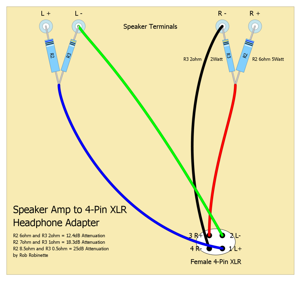
This adapter will work with single-ended and balanced output speaker amplifiers. Click the image to download the editable DIYLC file.
Rob Robinette
References
RCA Corporation, RCA Receiving Tube Manual, RC30.
Merlin Blencowe, Designing Tube Preamps for Guitar and Bass, 2nd Edition.
Merlin Blencowe, Designing High-Fidelity Tube Preamps
Morgan Jones, Valve Amplifiers, 4th Edition.
Richard Kuehnel, Circuit Analysis of a Legendary Tube Amplifier: The Fender Bassman 5F6-A, 3rd Edition.
Richard Kuehnel, Vacuum Tube Circuit Design: Guitar Amplifier Preamps, 2nd Edition.
Richard Kuehnel, Vacuum Tube Circuit Design: Guitar Amplifier Power Amps
Robert C. Megantz, Design and Construction of Tube Guitar Amplifiers
Neumann & Irving, Guitar Amplifier Overdrive, A Visual Tour It's fairly technical but it's the only book written specifically about guitar amplifier overdrive. It includes many graphs to help make the material easier to understand.
T.E. Rutt, Vacuum Tube Triode Nonlinearity as Part of The Electric Guitar Sound