[ How Tube Amps Work ] [ How the 5E3 Deluxe Works ] [ 5E3 Deluxe Mods ] [ Deluxe Models ] [ Amp Troubleshooting ] [ 5F6A Bassman Mods and Info ] [ How the AB763 Deluxe Reverb Works ] [ Tube Bias Calculator ] [ Overdrive ] [ Deluxe Micro Amp ] [ Bassman Micro Amp ] [ Champ Micro Amp ] [ My 5E3 Build ] [ Reverb & Tremolo ] [ SixShooter ] [ Spice Analysis ] [ VHT Special 6 Ultra Mods ] [ Telecaster Mods ] [ Android Tube Bias Calculator App ] [ The Trainwreck Pages ] [ Fender Input Jacks ] [ B9A Prototype Board ]
Switchable Cascaded Inputs for High Gain Channel
This is my third favorite 5E3 mod (behind Switched Negative Feedback and PRE Phase Inverter Master Volume). I wanted a Marshall style lead 'Gain Channel' for my Fender 5E3 Tweed Deluxe kit amp. This simple mod is like having a built-in all tube overdrive pedal. It reroutes the Normal channel after it goes through the V1A preamp tube into the Bright channel to cascade their gain stages together. The result is the Normal channel becomes a 'Gain' channel who's gain is controlled by a dedicated 'Gain' preamp volume control so you can dial in as much tube overdrive as you want.
The cool thing is you can dial in preamp tube overdrive even at very low 'Master' volume levels. Also the Bright Channel is completely unchanged--it sounds exactly the same after this mod so you can still get all the sweet 5E3 Deluxe tone you need. There's even a switch option shown below so you can switch between a completely 'normal' 5E3 and this cascade mod. The Cascade Channel mod is simple to do and simple to reverse if you ever want to go back.
5E3 Deluxe With Cascaded Channels - Basic Mod
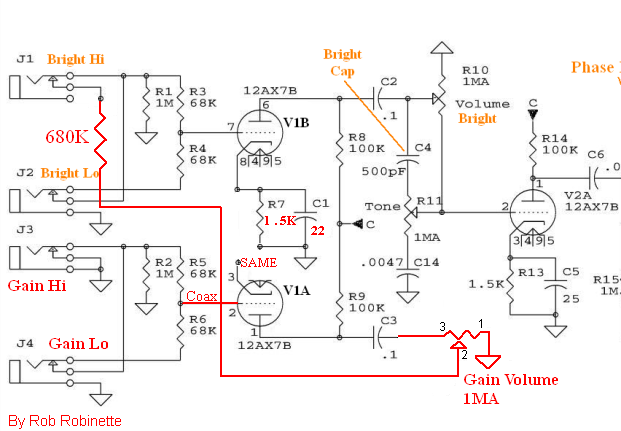
Changes in red. Normal Channel is rerouted to Bright Hi input jack switch terminal. Normal Volume pot becomes 'Gain' Volume. V1A and B's cathodes must be separated by installing a 1.5k ohm (1/4watt or higher) cathode resistor and one or two 22µF 25v cathode resistor bypass capacitors on V1A and V1B's cathodes (pins 3 & 8). The Gain Volume pot uses pin 3 for input and pin 2 (center wiper) for output. A 680k ohm resistor is added to pin 3 to limit Gain Channel gain.
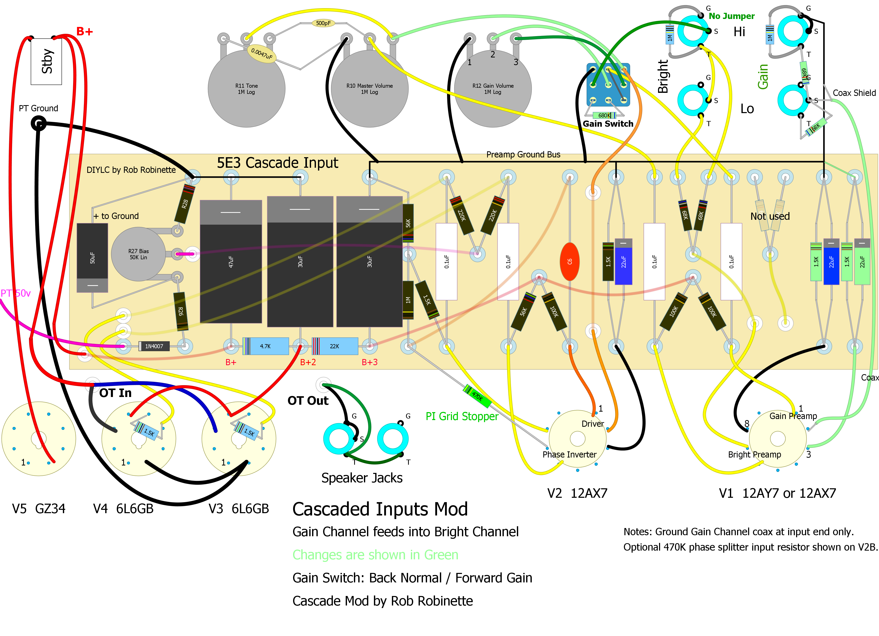
Simple Cascade--No Switch and No Coax
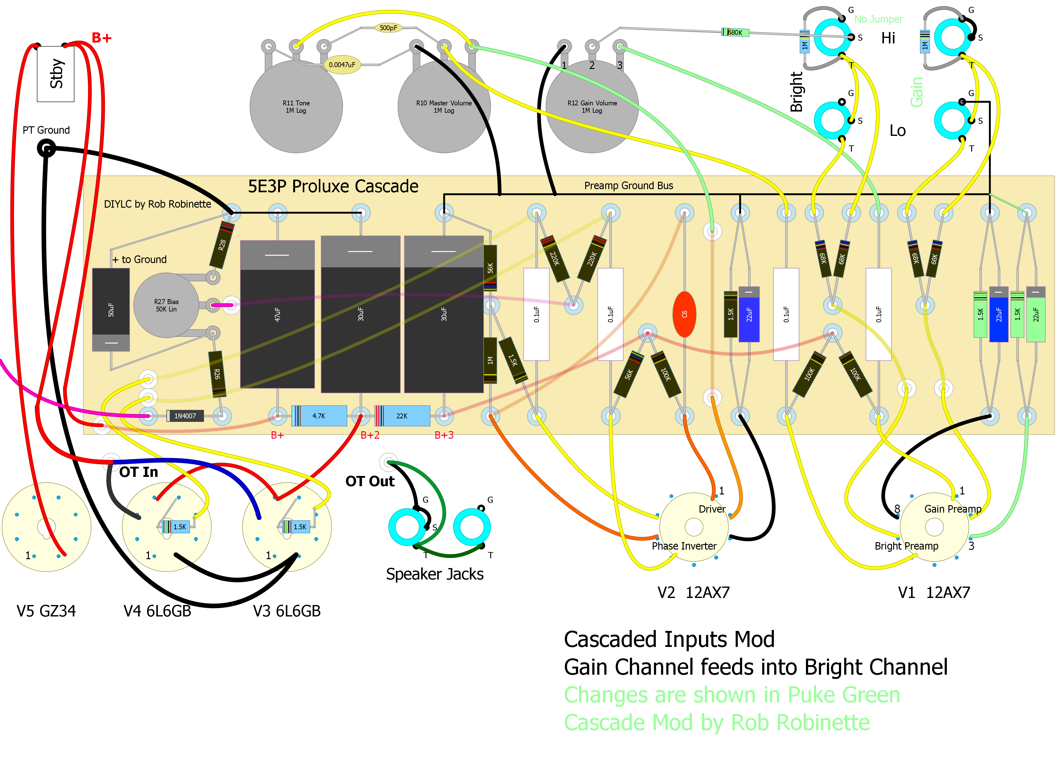
Click on the image above for the full size layout. Changes are shown in 'Puke' Green. 'Gain' Channel gets amplified by V1A then feeds into the Bright Channel. The Normal Volume control becomes the Gain control and the Bright Volume control becomes the 'Master' Volume. Notice the V1 cathode bias resistors and caps at the far right of the circuit board. To separate V1A and B's cathodes you must change the existing cathode resistor from 870 ohms to 1.5k and install an additional 1.5k cathode resistor (a 22µF 25v bypass cap is optional for V1A as the extra gain it gives isn't needed). You must cut or remove the jumper on socket V1 between the cathodes (pins 3 and 8). You can download the editable DIYLC (DIY Layout Creator) layout file here: images\Guitar\5E3P_Build\5e3p_Tube_Guitar_Amplifier_Cascade_Inputs_Coax.diy
When using the Bright Hi Channel simply turn down the Gain Volume and use the Master Volume and the amp will sound completely normal. The Gain Volume does interact with the Bright Lo volume so use both the Gain Volume and the Master Volume to control the Bright Lo volume.
Plug into the Gain Channel and use the Gain Volume to control the overdrive and use the Master Volume to control the overall volume. The new Gain Channel has a Hi and Lo input with the Lo input having the standard 6dB less signal.
This simple mod entails rerouting three wires at the volume controls, adding a resistor and separating the V1A and V1B cathode grounds.
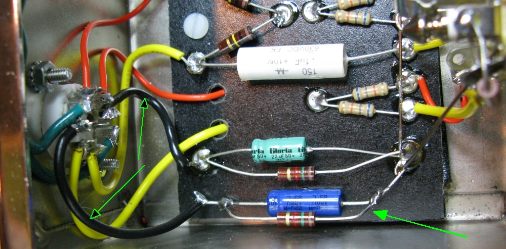
Separated Cathode Resistors & Caps
Cascade Mod + Gain Channel Coax
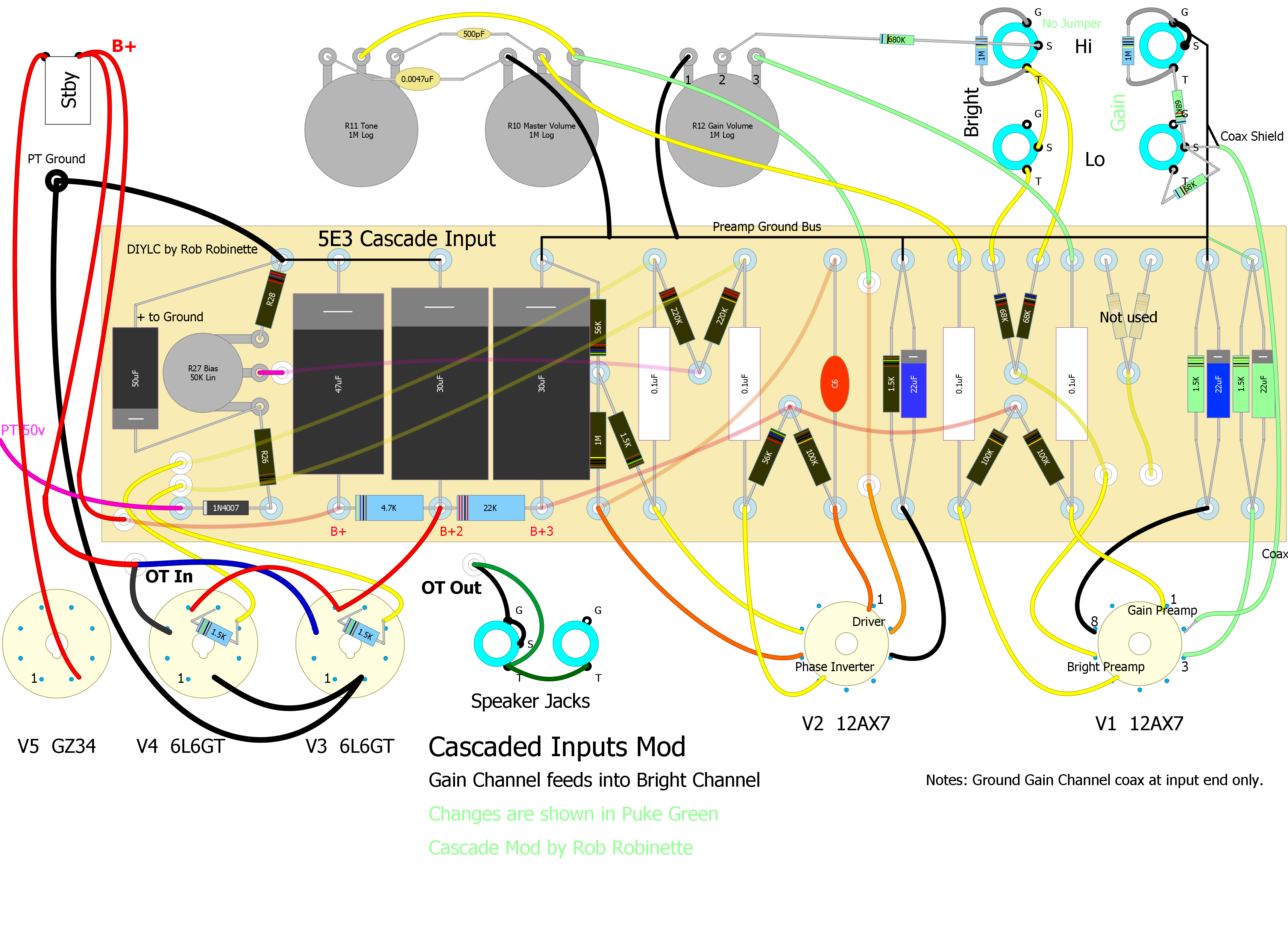
I recommend the use of coax for the Gain Channel. Using RG-174 coax from the Gain Channel input jacks to V1A can reduce noise. Putting the 68k grid stopper resistors on the input jack will reduce the input path's exposure to noise. Do not ground the coax shield at the tube end, only ground it to the Preamp Ground Bus or a Gain Channel input jack ground tab.
68k Grid Stopper Resistors Directly to Coax
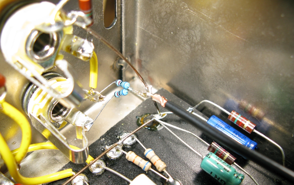
The coax shield is connected to the preamp ground bus bar to the right of the resistors. This is how I did it but the layout diagram shows a better, more secure way to mount the resistors.
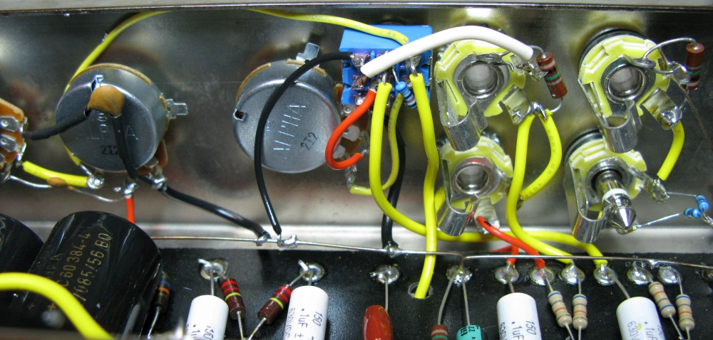
Coax Connected to V1A Pin 2
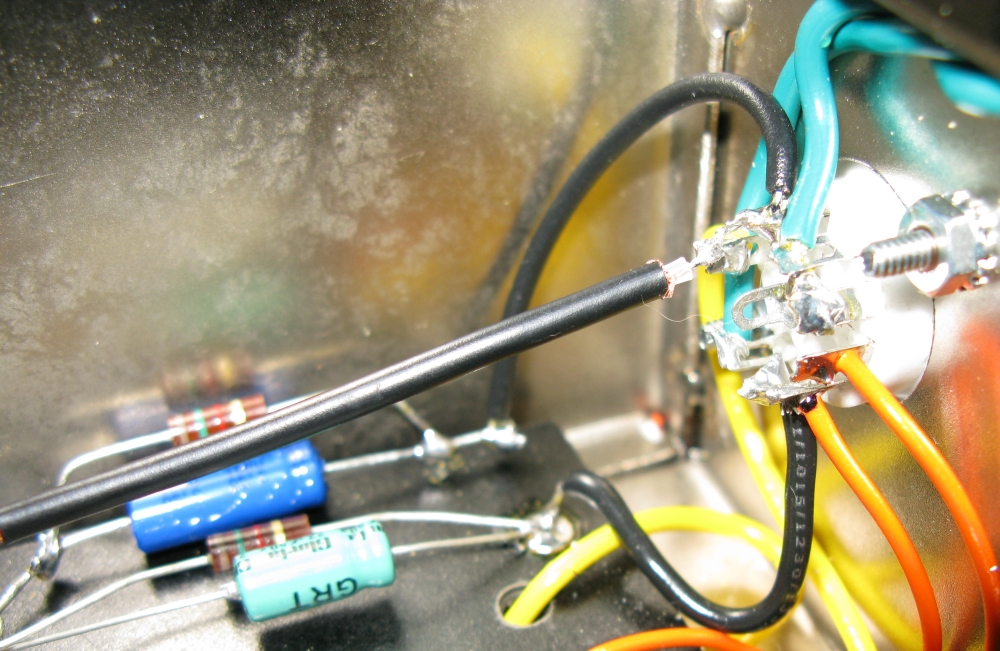
Coax shield is not grounded at this end. In this picture it looks like pin 3 is shorting to pin 2 but it isn't.
An Optional Switch for Standard 5E3 Parallel or Cascaded Inputs
This is what I did and I really like being able to switch back and forth between standard 5E3 and cascaded channels. With switch lever IN you get standard 5E3 parallel input channels. With switch OUT the Normal Channel cascades into the Bright Channel for preamp tube overdrive.
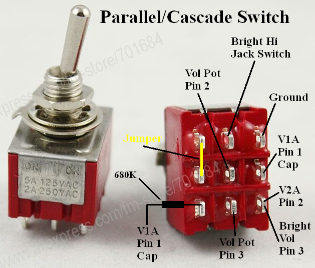
This ON-ON 3PDT switch will allow you to move between standard parallel 5E3 channels and cascaded overdrive. With the switch in 'Parallel' the only difference between a stock 5E3 is the separated cathode resistors on V1 which will have no impact on tone.
Parallel/Cascade Switch Installed
It's not pretty but it works great--this is a very cool mod.
One other modification I recommend with the cascaded overdrive channel is to add a Pre Phase Inverter Master Volume or simply add a 470KΩ 1/2 watt grid stopper resistor to the V2B Phase Inverter input (V2 pin 7) to smooth out the Phase Inverter overdrive tone. The cascaded overdrive signal can really overwhelm the Phase Inverter and cause severe and nasty sounding clipping. A Pre Phase Inverter Master Volume will allow you to control how much Phase Inverter distortion is fed into the Power Tubes. These modifications can really sweeten the 5E3's overdrive tone. By adding a resistor or master volume the 5E3's sweet preamp tube distortion won't get chopped up in the phase inverter.
I'm very happy with the cascaded channel mod. I can dial in tube overdrive distortion on the Gain channel even at low Master volume levels and the Bright Hi channel is completely 5E3 Deluxe. You can also dial the Gain volume down and get a normal sounding Normal Hi and Lo tone.
Gain Channel Measurements
Signal generator 400Hz 91mv rms tone was injected into the guitar input jacks. Measurements were taken after one and two stages of amplification.
Gain - Hi Channel One Stage of Amplification
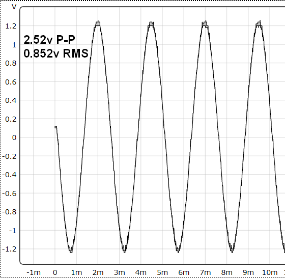
This is the 400Hz signal after going through just the Gain Channel amplification (V1A) with the Gain Volume set to max (12). Measured at Bright Hi input jack tip.
Signal gain for the Gain Channel gain stage = 0.852v rms out / 0.091v rms in = 9.36
The Gain - Lo Channel measured 0.44v rms with a signal gain of 0.44v / 0.091 = 4.8
The gain values for the Gain Channel are relatively low due to the 470k resistor placed at the Gain Volume input.
Gain - Hi Channel Measured at Master Volume Input - No Distortion
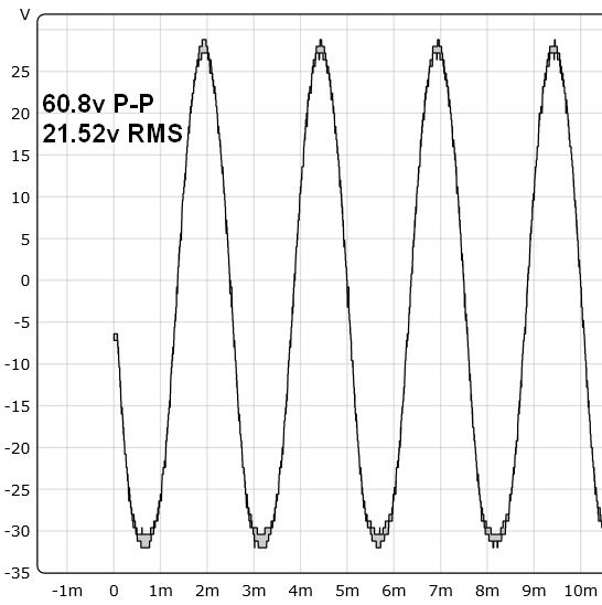
The signal has now passed through the Gain Channel and Bright Channel amplification (V1A and B) with Gain Volume at max and the Master Volume at 9. This is the max voltage before distortion set in.
Signal gain for the Gain Channel gain stage cascaded into the Normal Channel gain stage = 21.52v rms out / 0.852v rms in = 25.3
Gain - Hi Channel Measured at Master Volume Input - With Distortion
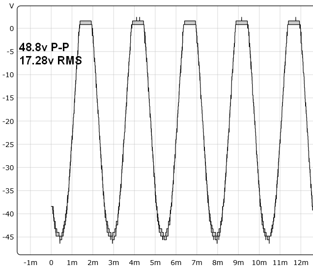
Conditions here are the same as above except the Master Volume is set to max (12). Max output dropped once distortion set in. This is all preamp distortion. The 5E3's phase inverter will also be driven into overdrive distortion and can add unpleasant content to the output tone.
By Rob Robinette
[ How Tube Amps Work ] [ How the 5E3 Deluxe Works ] [ 5E3 Deluxe Mods ] [ Deluxe Models ] [ Amp Troubleshooting ] [ 5F6A Bassman Mods and Info ] [ How the AB763 Deluxe Reverb Works ] [ Tube Bias Calculator ] [ Overdrive ] [ Deluxe Micro Amp ] [ Bassman Micro Amp ] [ Champ Micro Amp ] [ My 5E3 Build ] [ Reverb & Tremolo ] [ SixShooter ] [ Spice Analysis ] [ VHT Special 6 Ultra Mods ] [ Telecaster Mods ] [ Android Tube Bias Calculator App ] [ The Trainwreck Pages ] [ Fender Input Jacks ] [ B9A Prototype Board ]