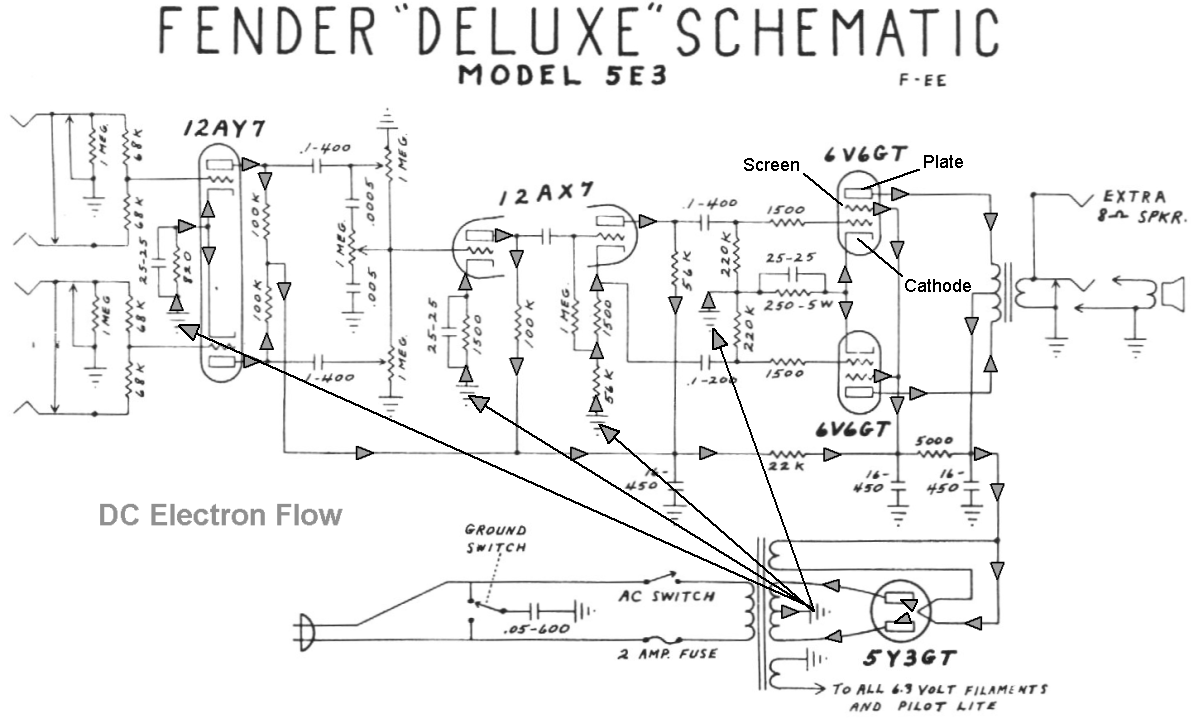
How Tube Amplifiers Work
By Rob Robinette
Have you ever looked at the guts of a guitar amplifier and wondered what all those parts do? Well, I'll walk you through the signal flow and discuss the components in this very simple but great sounding 1950's Fender 5F1 Champ guitar amplifier. Once you understand the simple 5F1 you'll be able to understand more complicated amps. 5F1 was Fender's internal model code for the 1950's tweed Champ. Although this page discusses Guitar tube amps everything here applies to audio stereo tube amplifiers too with the goal of distortion prevention in audio amps being the biggest difference.
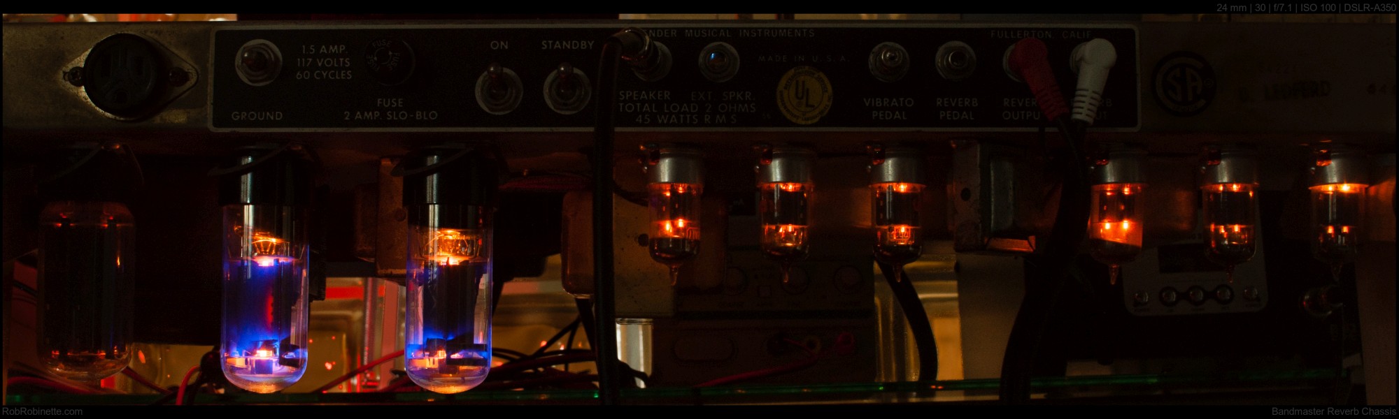
5F1 Champ Amplifier
5F1 Chassis
Volume control on top, Circuit Board inside, tubes on bottom: V1 Preamp Tube on right, V2 Power Tube in center, V3 Rectifier Tube on left. The Power Transformer and Output Transformer are attached to the other side of the chassis.
WARNING: A tube amplifier chassis contains lethal high voltage even when unplugged--sometimes over 700 volts AC and 500 volts DC. If you have not been trained to work with high voltage then have an amp technician service your amp. See more tube amplifier safety info here.
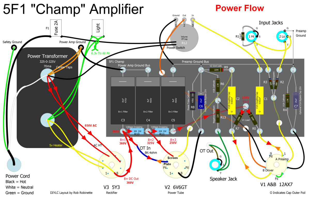
We'll start with the amplifier layout diagram. If things get too cluttered you can refer back up to this clean diagram. The guitar input jacks are at the upper right, the circuit board is in the center, the power transformer (PT) is on the left and the tubes and speaker jack are at the bottom. The output transformer (OT) is not shown but "OT In" are the output transformer primary wires and "OT Out" are the secondary wires.
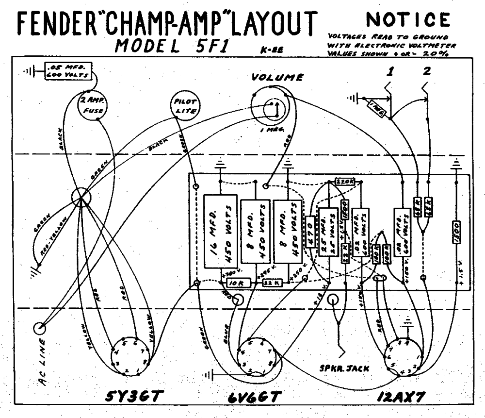
5F1 Champ Guitar Amplifier Layout Diagram
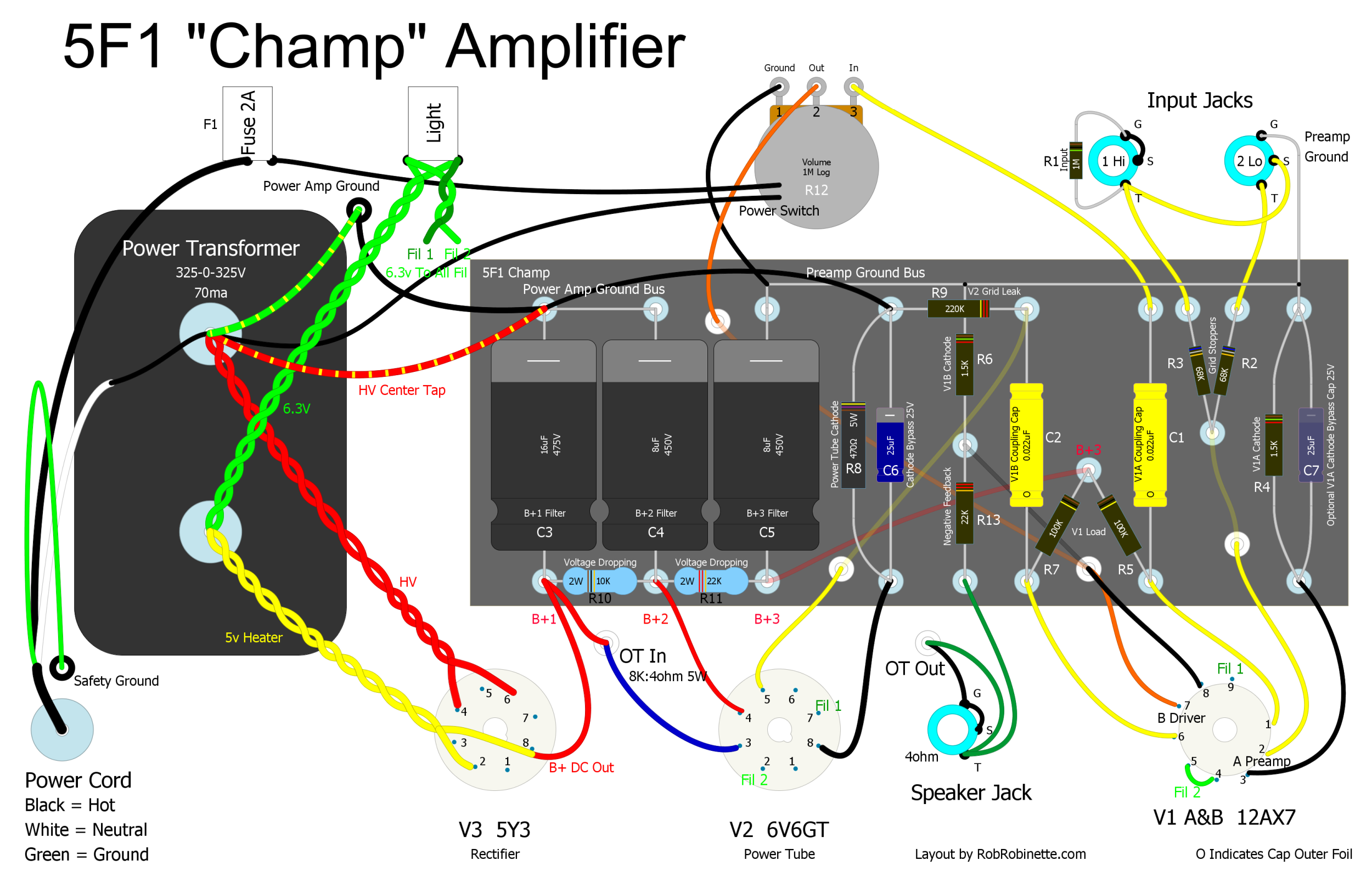
I added component numbers to this layout that match the schematic diagram below. Compare this to the picture of the chassis above. I have had questions about the grounding scheme shown in this layout. Grounding the V2 power tube grid leak (R9) and the power tube cathode resistor (R8) and cathode bypass cap (C6) to the first filter capacitor's ground (C3) is best practice and should result in a quieter amp. Click the image to download the pdf.
Annotated Layout With Signal Flow and Component Function
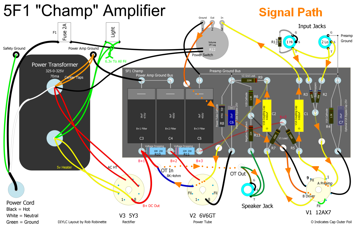
Tracing the signal path on this layout diagram and the schematic below will help you understand how this amp works.
Signal Flow Overview
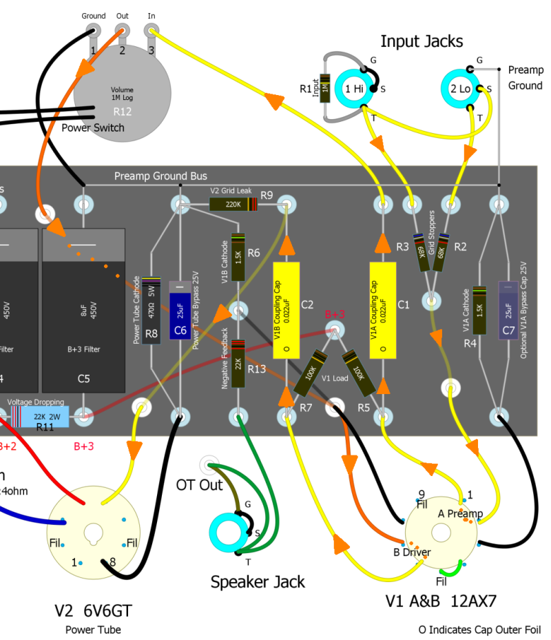
Signal flow is shown above and below (orange arrows above, fat red line below). Signal from the guitar enters at upper right guitar Input Jack 1 or 2 and flows down to the circuit board and then to the preamp tube V1A at bottom right where the signal goes through its first stage of amplification. The signal then goes up to the circuit board and on to the volume control at top center, then back down to tube V1B (the second half of the first tube) for its second stage of amplification. From there the audio signal goes back to the circuit board then down to the power tube V2 for the third stage of amplification. V2's output goes out the blue wire to the output transformer (not shown) for a current boost, then from the output transformer via the green wire to the speaker jack (to the right of V2) and on to the speaker. I have added component numbers to the layout diagram above that match the schematic below.
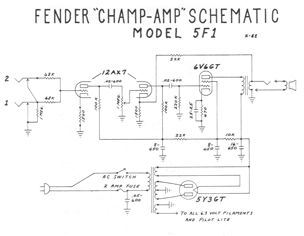
Annotated Weber 5F1 Schematic
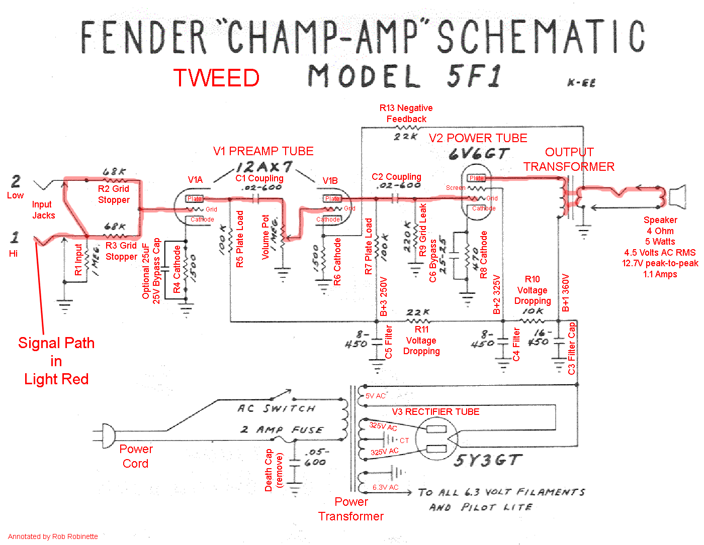
The signal flow in red seems much simpler on the amp's schematic. Component numbers match the Layout diagram above. V1A is one half of tube V1, V1B is the other half. Voltages shown are approximate. Click the image for the full size schematic. Click here for the clean schematic.
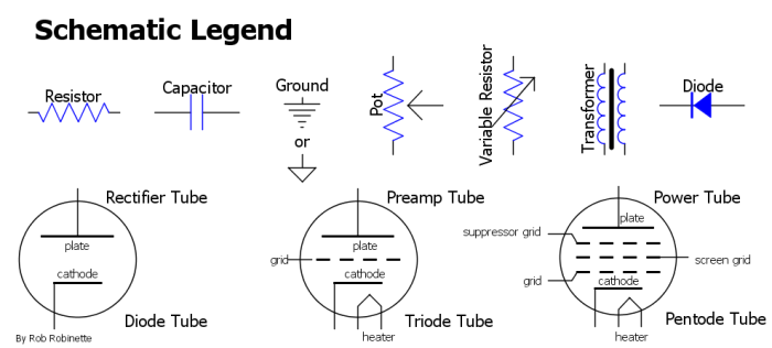
These are pretty much all the symbols you'll need to know to read tube amp schematics.
Table of Contents
How Cathode Bypass Capacitors Work
The Long Tail Pair Phase Inverter
Ultra-Linear Output Transformers
Impedance Mismatch Between the Power Tube and Speaker
Magnatone 280 Amp With Stereo Harmonic Pitch-Shift Tremolo
How Humbucking Guitar Pickups Work
Transistor Equivalent Circuits
Calculating Parallel Resistance
How Voltage Dividers and Pots Work
Measuring In Circuit Resistance
Your Calculator's Engineering Mode
How Amps Work
The next few paragraphs will help you visualize the flow of electrons through simple circuits. Learning to visualize the flow of individual electrons was a breakthrough for me in understating tube amplifier electronics.
Electric guitars generate an alternating current (AC) audio signal. The guitar's pickups are small electric generators. Pickups have magnets (poles) that magnetize the metal guitar strings. The movement of the magnetic field surrounding the magnetized strings generates electricity in the pickup's coil. The coil is simply a thin insulated wire wrapped around a spool and when a magnetic field cuts through a coil of wire it generates an electric voltage (electronic pressure) and current (electron flow) in the coil's wire.
Guitar Pickup
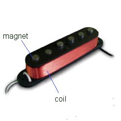
The black and white wires leaving the guitar pickup are the two ends of one long coil wire. A humbucker pickup is simply two of these coils connected end-to-end (in series).
Standard Guitar Circuit
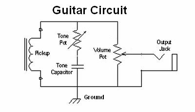
The Pickup on the left is a wire coil that generates the guitar signal. The Tone Control bleeds high frequencies to ground. The Volume Pot is wired as a variable voltage divider. The Volume Pot bleeds guitar signal to ground to lower the guitar's output volume.
I've been asked many times, "What is voltage?" It's pretty simple really. Like electrical charges repel the same way like magnetic poles repel. So if you cram a bunch of negatively charged electrons together onto the metal plates of a battery their negative charges repel one other--they want elbow room. The tighter they are packed together the higher the pressure so I like to think of negative voltage as electron pressure.
A quick note about 'Conventional Current Flow.' In electric circuits negatively charged electrons actually flow from the negative '-' battery terminal to the positive '+' terminal. That's right, the electricity in your car flows from the battery's - terminal through the ground wire, through the car's body, through the radio's ground wire to the radio and then through the positive power wire back to the battery. The problem is that Benjamin Franklin guessed wrong on the polarity and direction of electrical flow so conventionally we think of electricity as flowing from + to -. People say electric current flows + to - (conventional current flow) but electrons flow - to +. With tube electronics it's easier to think in terms of how the electrons are really moving in order to understand them.
If you connect a wire across a battery's terminals the jammed together electrons in the negative terminal see the wire as a pipe with lots of room so they flow down the wire. When you have an 'excess' of electrons tightly packed together you have negative voltage. When you have a 'scarcity' of electrons, or electrons are pulled apart from one another, you have a positive voltage.
When I think about a wire with very high positive voltage on it I imagine the wire as an empty pipe with very few electrons in it with lots of 'elbow room' so electrons really want to flow into that wire. Ground or earth represents an unlimited supply of electrons at zero volts (or neutral voltage). Touch that high voltage wire wire to a ground and the electrons hanging out there will rush in to fill the void of electrons in the wire. Voltage is the force of electrons wanting to move from a conductor crowded with electrons to a conductor with fewer electrons and more elbow room. Current is the measure of how many electrons are flowing through a conductor--the more electrons flowing, the higher the current. Keep this in mind when thinking about amp circuits, high voltage is an extreme scarcity of electrons and ground represents an unlimited supply of electrons.
As a guitar string vibrates it moves one way and generates a positive voltage in the pickup coil, then as the string reverses direction the voltage is reversed and a negative voltage is generated. This occurs with every string vibration so an alternating current (positive-negative-positive-negative. . .) makes up the audio signal put out by the guitar. I'll repeat that because it's a very important concept, as the guitar string moves one direction over the guitar pickup coil it generates a negative voltage (excess electrons), then as the string reverses direction the electron pressure (voltage) and electron flow (current) reverses too and a positive voltage is generated (scarcity of electrons) and this repeats with every vibration of the string creating an Alternating Current (AC) electrical signal. This is why guitar audio signals are AC, or alternating current--as the strings alternate their direction of travel the signal voltage alternates between + and -. This tiny little AC signal is what the guitar amp will amplify until it's strong enough to move a speaker cone in and out. The speaker cone alternates in and out with the alternating current from the guitar's pickup coil. For every guitar string movement there is a corresponding speaker cone movement.
An AC guitar audio signal on a wire alternates between positive and negative voltage. A negative signal voltage packs electrons closer together (excess of electrons = negative voltage). The positive half of the AC guitar signal pulls electrons apart and creates a scarcity of electrons. Remember, voltage = electron pressure.
If you graph a guitar audio signal the pitch of the guitar string's sound is expressed as wave spacing (frequency) and loudness is expressed as wave height (amplitude). A high frequency sound will have tight wave spacing and a low frequency sound will have wide wave spacing. In the graph below the high E string is on the left and the low E is on the right. A quiet sound will have short waves and a loud sound will have tall waves.
The direct relationship between string movement and electricity generated in the pickup coil is the key to understanding guitar amplification. Our guitar amplifier will simply make the electric audio waves taller to boost their loudness.
When multiple strings are played the multiple electric waves are summed into complex waves. See my short youtube video to see guitar audio on an oscilloscope.
Guitar AC Voltage Audio Signal
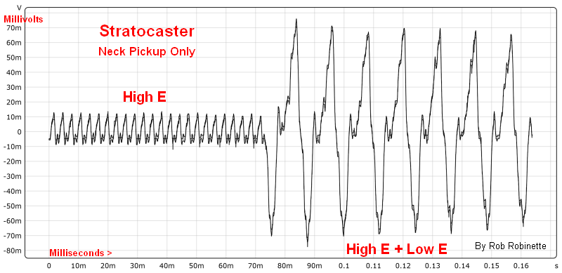
Fender Stratocaster connected directly to an oscilloscope. Each 'wave' on the oscilloscope is caused by one string vibration. The highest voltage (peak of wave) is created by the fastest string speed when it's moving directly over the pickup. The zero voltage point (center of graph) is when the string stops moving and reverses its direction. The left side of the graph shows a high open E string pluck followed by a pluck of the low open E. Voltage is on the left scale and time runs along the bottom. The top half of the signal is positive voltage and the bottom half is negative. The signal's voltage and current alternate between positive and negative. The tight wave spacing on the left is an indication of high frequency and pitch. The wave height is an indication of power and loudness. The high open E + low open E strings' signal on the right is a summation of the two strings' signals combined into a complex wave--the high open E wave is 'written' onto the large low open E wave. The speaker cone will move just like this graph. Every little twitch on that line makes the speaker cone twitch. When the graph goes high with a positive voltage the speaker cone moves outward, when the graph goes low with a negative voltage the cone moves inward.
WARNING
Amplifiers have large capacitors that store enough electricity to kill even when the amplifier is unplugged. If you open an amplifier you MUST verify no voltage remains in the capacitors before working inside it.
Guitar Audio Signal Input
The guitar cable's tip conductor connects to the input jack's "T" tip terminal. The cable's sleeve connects to the "G" ground terminal. The guitar signal travels down the wire and through grid stopper resistor R3.
The guitar's alternating current audio signal enters the amplifier at guitar input jack 1 or 2. 1 is the Hi input and 2 is the Lo, -6dB quieter input. Resistor R1 on jack 1 is the 'input resistor.' It sets the amp's input impedance to 1,000,000 ohms (1M) to boost the signal voltage from the guitar. [Bonus info: R1 also functions as the 'grid leak' resistor for Tube V1A's grid. A grid leak drains off unwanted DC voltage to keep the tube's control grid near 0 DC volts.] The '1M' written on R1 is its rating of 1 megaohm. See more on impedance here and see this web page for grad school level information on how Fender multiple input jacks and jumpering channels works.
The signal moves from the guitar jacks down the yellow wires to resistors R2 or R3, which are 'grid stopper' resistors. They help stabilize the amplifier by removing much of the audio signal above human hearing. The "68K" written on the resistor refers to its resistance value of 68,000 ohms or 68 kilohms. [Bonus info: R2 and R3 also act as 'mixing resistors' and prevent interaction between two simultaneous inputs like two guitars or a guitar and microphone. Sometimes you will see resistor values written as 1K5 which simply means 1.5 kilohms.]
Preamp Stage
Signal from resistor R3 travels down the wire to tube V1A's grid (pin 2) then out the plate to coupling capacitor C1. Tube V1 is split into two identical halves, A & B.
After going through grid stopper resistor R3 the audio signal flows down the wire to the preamp tube's control grid, which is the entry to the 'A' half of the preamp tube (V1A). It's called V1A because tubes were called 'Valves' and this is tube number 1 and we're using the 'A' half of the tube. 12AX7 is the type of tube which happens to be the most popular preamp tube in use and it's really two tubes in one.
I recommend you now read How Tubes Work and come back here when finished.
The preamp tube amplifies the guitar audio signal then sends it out pin 1 (plate) up the yellow wire to capacitor C1, which is a 'coupling capacitor' or 'cap.' Coupling caps are sometimes also called 'blocking caps' because they block DC voltage but allow the AC guitar signal to pass. The 0.022uF written on the cap is it's rating of 0.022 microfarads (0.000,000,022 Farads). In some old documents you'll see "micro-micro" or "uu" which means pico Farad.
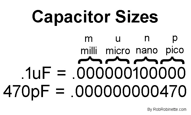
Use this chart to help convert capacitor size such as: .1uF = 100nF and 1nF = 1000pF.
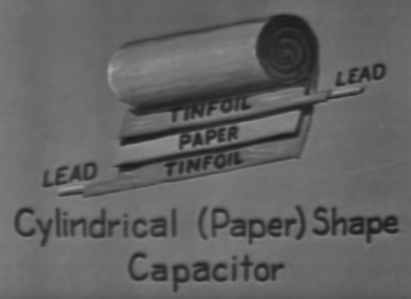
Capacitors are made of two conductive plates separated by an insulator or dielectric. Common dielectrics are mica, polypropylene, ceramic and even paper and oil.
How capacitors block DC but let AC pass: Caps are made with sandwiched but separated conductive plates. The separated plates cannot flow DC current but AC fluctuates between positive and negative voltage. When the AC guitar signal negative voltage (excess electrons) is applied to the input plate the electrons repel electrons on the output plate so they move off the plate and flow out of the capacitor. When a positive voltage is applied (scarcity of electrons) to the input plate the output plate attracts electrons so electrons flow into the capacitor.
That's how capacitors really work but I like to visualize them as having a stretchable rubber membrane inside that blocks the flow of electricity. When voltage is applied to a capacitor the 'rubber membrane' stretches and bulges as electrons try to flow through it. The higher the voltage the more the membrane bulges. If you quickly reverse the capacitor's voltage polarity it will go from bulging one way to bulging the other way. This is what a small AC signal does--it stretches the 'membrane' back and forth as the voltage alternates which allows electrons on both sides of the capacitor to move back and forth (alternate) but a constant DC voltage that is trying to flow in one direction will be blocked by the membrane.
If you are familiar with hydraulics a coupling capacitor is like a piston in a hydraulic line. Small alternating pressure changes will make the piston move back and forth so fluid is moved on both sides of the piston -- this is how small alternating current signals move through a capacitor.
High voltage DC (direct current) power used by the tube is brought in through resistor R5, which is a 'load resistor.' We'll discuss the function of the load resistor later. The wire between tube pin 1 (plate) and R5 carries up to 250 volts DC. That wire carries both the AC audio signal out and the high voltage DC power the tube needs in. Coupling capacitor C1 allows the AC audio signal to pass through but blocks the DC on the wire and keeps it out of the volume pot.
Volume and Output Stage Driver
Signal flows from capacitor C1 to the Volume pot then down the orange wire to tube V1B's grid (pin 7) then out the plate (pin 6) to capacitor C2, then to a fork in the road--resistor R9 one way and the other way down the yellow wire to the power tube V2.
After going through capacitor C1 the audio signal flows up the yellow wire to the volume potentiometer (pot) which acts as a variable voltage divider. Volume knob left = more signal bled to ground and lower volume. Volume knob right = less signal bled to ground and higher volume. [Bonus info: The volume pot also functions as V1B's grid leak resistor] For more info see voltage dividers and potentiometers.
The signal then flows from the volume pot down the orange wire all the way to tube V1B's pin 7 (grid). V1B is the second half of the preamp tube. This second gain stage is called the output stage driver because it boosts the signal to the level needed by the power tube. The audio signal leaves tube V1B via pin 6 (plate) and flows up the yellow wire to capacitor C2, another coupling cap that blocks DC. High voltage DC is fed to the tube via load resistor R7. After C2 the signal flows down the yellow wire to the power tube's pin 5 (grid). Resistor R9 has a dual function. It adds input impedance to the power tube amplifier circuit and acts as the tube's 'grid leak' resistor which keeps the grid at 0 volts DC.
Power Tube to Output Transformer to Speaker Jack
Signal leaves V2's pin 3 and flows out the blue wire to the Output Transformer's primary winding then out the secondary winding to the speaker jack.
The power tube, V2 is sometimes referred to as the output tube. V2 is the final stage of amplification and its purpose is to amplify for power (voltage x current) where V1A and V1B were focused on voltage amplification. The signal enters the power tube at pin 5 (grid) and leaves via pin 3 (plate). It then goes to the output transformer (OT) which is mounted on the backside of the chassis and is not shown on the layout diagram.
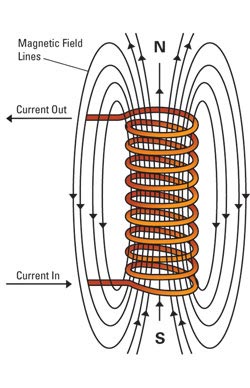
Like we saw with the guitar's pickup, magnetism can be used to generate electricity in a coil. You can also do the reverse and pass electricity through a coil and generate magnetism. The amplifier's output transformer uses both of these principles to pass alternating current (AC) from its primary (input) winding to the iron core as magnetic flux and on to the secondary (output) winding as alternating current.
The output transformer's windings are really just two wire coils wrapped around an iron core. The input, or primary winding uses electric current flowing through it to generate a magnetic field or flux. This magnetic field fluctuates with the guitar AC signal voltage and is captured by the transformer's iron core. The captured magnetic flux flowing through the core generates a voltage and current in the secondary winding. You can alter the voltage and current from primary to secondary by changing the ratio of coil wraps from primary coil to secondary.
Transformers
![]()
![]()
Current flowing into the primary winding (above left) induces magnetic flux flow around the transformer iron core which in turn induces an electric voltage and current in the secondary winding. Put fewer wire wraps on the secondary (output) winding and its voltage will decrease (step down) but its current will increase. Most guitar amp transformers are of the 'double window' type (bottom of left diagram) and made with laminated iron magnetic cores. 5F1 transformers are shown on the right. The Power Transformer is lying on its side while the Output Transformer is standing vertically. Positioning transformers 90º out of phase with one another like this reduces interference hum.
Example: The primary winding has 200 wraps of wire in its coil and the secondary has 100 wraps. If a 10 volt alternating current is applied to the primary winding the secondary will generate 1/2 of the input or 5 volts. The current will change proportionally in the opposite direction. If 1 ampere of AC current is applied to the primary the secondary will generate 2 amps. This is what an amplifier's output transformer does, it steps down the signal's voltage but steps up the current because the speaker's voice coil needs current to generate a magnetic field to move the speaker cone.
The output transformer's primary takes in a high voltage, low current signal (high impedance signal) and puts out a low voltage, high current signal (low impedance signal) through the green wire to the speaker jack and on to the speaker. For you mechanical types you can think of the output transformer as a gearbox that alters speed (voltage) and torque (current). The power tubes send large voltage swing into the output transformer and you can think of this as high speed from an "engine". The transformer gears this high speed (high speed, low torque=high voltage, low current) down for much less speed (less voltage swing) but much more torque (current).
The alternating current audio signal flows through the speaker's voice coil which generates a magnetic field. The voice coil is simply a single wire wrapped into a coil as shown below. The magnetic field created by the voice coil is either attracted to or repelled by the speaker's magnet. Positive voltage generates a repulsive magnetic force and the speaker coil and cone moves outward away from the speaker magnet, negative voltage generates an attractive magnetic force and pulls the speaker cone inward. The speaker cone alternates between moving outward and inward as the signal voltage alternates between positive and negative. For every guitar string movement there is a corresponding speaker cone movement.
Speaker Voice Coil is an Electromagnet
Electric current flowing through the speaker's voice coil generates a magnetic field. When the electric current in the voice coil reverses, the magnetic field also reverses causing attraction and repulsion to the speaker magnet.
This magnetic attraction and repulsion moves the voice coil and speaker cone back and forth to create air pressure waves that our ears perceive as sound--the sweet sound of electric guitar. When the speaker cone moves outward a positive air pressure wave is created and when the cone moves inward a negative (low pressure) wave trough is generated. These air pressure waves move our ear drums in and out. The ear drum movement is translated into neuron activity which is sent to the brain where pleasure is created, thus electric guitar + amp = pleasure ;)
Bonus Info: You can determine the ohm rating of a guitar speaker by measuring the DC ohms (resistance) between the speaker terminals (while disconnected from the amp) and then multiply by 1.2. Example: You measure 6.5 ohms: 6.5 x 1.2 = 7.8 ohms = 8 ohm speaker.
Speaker
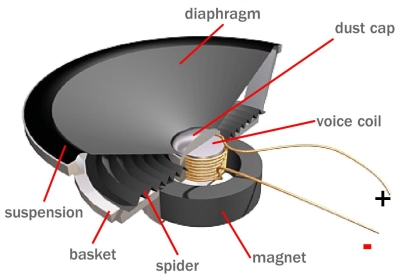
The 'voice coil' is an electromagnet that interacts with the speaker magnet. The 'spider' supports the voice coil but allows it to move in and out freely. This excellent DIY speaker recone video shows speaker parts and function in detail.
Bonus Info: How Microphones Work
Dynamic microphones work exactly in reverse of how a speaker works. They have a diaphragm like a speaker cone that gets moved by sound (air pressure waves). The diaphragm moves a coil of wire wrapped around a magnet. The coil moving through the magnetic field creates electricity in the coil wire--an alternating current signal voltage.
Microphone
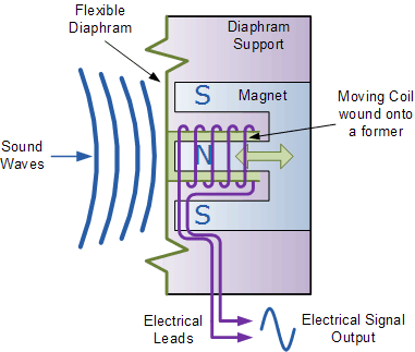
When the microphone diaphragm moves the coil, electricity is generated.
When a singer sings a note her vocal chords vibrate like a guitar string. The movement of the vocal chords create air pressure waves that strike the microphone diaphragm and cause it to move. Speaking of diaphragms, our ear drums are diaphragms that when moved by sound waves cause neurons to fire to communicate with our brain. Yea, our ears are biological dynamic microphones.
When a positive, high pressure sound wave hits the microphone diaphragm it is pushed inward and a positive electrical current and voltage are created. When the low pressure wave trough hits the diaphragm it is pulled outward and a negative current and voltage are created in the coil. The microphone creates an alternating current voltage signal similar to an electric guitar AC voltage signal.
Negative Feedback
The 5F1 amplifier uses negative feedback (NFB) to reduce distortion, increase headroom, decrease damping factor and improve stability but a drawback is it also reduces overall amplifier gain. Negative feedback works by taking the speaker output voltage and feeding it back into the amp's signal stream before the driver or phase inverter circuit. A feedback resistor reduces the voltage to a suitable level before it joins the amp's signal stream. It's negative feedback because the signal is out of phase so when it's injected into the amp's signal stream it reduces the amp's signal voltage.
A green wire running from the 5F1's speaker jack carries the amplified audio signal through resistor R13 and injects the feedback at V1B's pin 8 (cathode). Resistor R13 is the Feedback Resistor and controls the level of feedback voltage passed to the cathode. Adding a switch to the NFB circuit is a common modification. Removing feedback makes an amp more aggressive with earlier break up and distortion at lower volume levels.
So the main purpose of a guitar amplifier is to take the tiny AC electrical signal generated by the guitar's pickup coil and make it strong enough to push and pull a speaker cone. The guitar amp is also used to shape the tone and control signal distortion giving us the clean, mellow sound of jazz guitar or the animal growl of hard rock. Distortion is an important part of guitar amplifier design and this is the primary difference between guitar and audio amplifiers. Audio amps are usually designed for absolute minimum distortion.
Power Supply
Now that we've covered the signal flow I'll go back and cover the other amplifier components that I didn't mention. Wall plug power of 120 volts AC (USA or 100, 220 or 240 volts AC in other countries) runs to the fuse F1. Fender guitar amp fuses are MDL type "slow blow" or "time delay", size 3AG, 1/4 inch (6mm) wide by 1 1/4 inch (30mm) long. The fuse is a 250 volt, 2 amp slow blow fuse. Slow blow means it won't blow instantaneously when the turn-on power surge runs through it. Sustained current greater than 2 amps is required to blow the fuse. Next the power flows to the power switch S1, which is located on the volume pot.
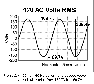
120 AC volts RMS (average) wall power equals 169.7 volts peak (Vp) and 339.4 volts peak-to-peak (Vpp).
Bonus Info: Alternating Current (AC) voltage is normally given in volts RMS (root-mean-square), which is a form of voltage averaging equal to a DC voltage. Always consider AC voltage as RMS unless it is specified as peak Vp or peak-to-peak Vpp. Multimeters show voltage in RMS. Our standard 120 volts AC wall power is RMS. You can convert RMS voltage to peak voltage by multiplying RMS by 1.414, so 120 volts AC at the wall is actually 169.7 volts measured from the + wave peak to 0. You can convert peak voltage to RMS by multiplying by 0.707. To convert RMS voltage to peak-to-peak voltage you multiply RMS by 2.828, so 120 volts AC at the wall is actually 339.4 volts measured from the + wave peak to the - wave peak. You can convert peak-to-peak to RMS by multiplying by 0.354.
AC voltage in the United States runs at 60 cycles per second, which is called Hertz (Hz). 120 volt wall power goes from zero to +169.7 volts, then down through zero to -169.7 volts, then back up to zero 60 times per second. This is why AC electrical noise picked up by guitar amps is often described as a 60 Hertz hum. Why is our wall power 60 cycles per second? Because power company electrical generators in the US turn at 60 revolutions per second (3600 revolutions per minute or RPM).
Bonus Bonus Info: Visualizing Alternating Current. One way to visualize how AC electricity flows is to think of the amplifier's power system as a rope and pulley system. Think of the wall power plug and the amplifier's power transformer as pulleys. A loop of rope representing the hot and neutral wires would be wrapped tightly around the wall power and transformer pulleys.
The power company's AC generator is like a hand grabbing the power rope (hot wire) and pushing it forward a few feet then stopping the rope movement and pulling the rope back, then pushing the rope again, then pulling it in this alternating pattern (doing one push-pull cycle 60 times per second). Electrons actually alternate their movement forward and backward, reversing course through AC wires and circuits like this rope movement.
Bonus Bonus Bonus Info: 240 volt circuits in the United States use two 120 volt hot wires instead of 120 volt's single hot wire and ground (called neutral). For 240 volts one wire pushes at +120 volts while the other pulls at -120 volts (like using two hands, one hand on each of the two ropes in the analogy above), then they alternate the pushing and pulling at the same 60 cycles per second for 240 volts of power. Alright, back to the amplifier. . .
After the amp's fuse and On/Off switch the 120v AC RMS runs to the power transformer (PT), through its primary winding, then back to the wall plug via the white Neutral wire. The white Neutral wire is a ground wire and is connected to the same ground as the Safety Ground wire at the building's electrical service entrance.
The 5F1's power transformer high voltage winding is rated at 325-0-325v. This means the transformer has a grounded 0 volt center tap and simultaneously puts out +325 volts AC RMS on one secondary winding wire and -325v on the other for a 650 volt AC RMS wire-to-wire voltage (650 volts AC RMS = 1,838 volts peak-to-peak :O ). Yes, that's high voltage that can kill you. At this very high voltage the 5F1 power transformer only needs to be rated for a paltry 70 milliamps (0.070 amp) max AC current to run the amp circuit.
The power transformer has three secondary windings. The first winding as discussed above steps the 120v RMS AC wall power up to 325 volts RMS AC. Two other small secondary windings step the 120v AC down to 6.3 volts RMS AC and 5 volts RMS AC. Notice all voltages in transformer secondaries are always AC because a transformer can't pass DC from primary to secondary. The 6.3 volts are used to power the pilot light and heat the preamp and power tubes' heater filaments which heat the tubes' cathodes. The 5 volts are used to directly heat the rectifier tube's cathode.
Bonus Info: When I first learned that the power transformer primary coil was made up of one long wire that directly connects the 120v hot wire to the neutral (ground) wire I wondered why it didn't short out. The reason is the primary and secondary coils are coupled together by the transformer's iron core. Alternating current in the primary coil creates a magnetic field or flux that is captured by the core. That flux in the core creates an AC voltage in the secondary coil. The load (impedance) placed on the secondary winding by the amplifier is transferred through the core to the primary coil. That impedance keeps the primary coil from "shorting out."
Power Cord Wiring
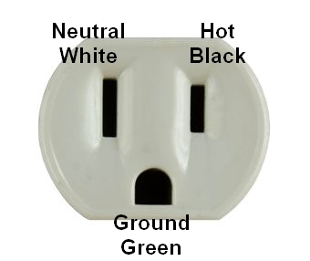
Modern U.S. wall cords and sockets have a narrow blade for Hot (black wire 120v), a wide blade for Neutral (white wire ground), and a round or 'D' shaped prong for the chassis Safety Ground (green wire ground). Power cord wire colors are sometimes non-standard so use a multimeter to identify Hot and Neutral. Europeans sometimes use the letters E: Earth (safety ground), L: Line (hot) and N: Neutral to describe the three plug wires.
The 325 volts AC power from the power transformer is fed directly into V3, the rectifier tube. V3 is a full wave dual plate rectifier tube that converts alternating current (AC) into direct current (DC). The power transformer and rectifier work together as an electron pump which pulls electrons out of the amp circuit creating a positive voltage (electron scarcity = positive voltage). The amplifier's electronics need DC to amplify. The amp is powered by DC but the guitar signal moving through the amp is AC.
The flow of power starts at the power transformer at far left. 325V AC on each high voltage secondary wire powers the V3 rectifier tube. V3 puts out 360V of DC. Note the yellow wires running to V1's pins 1 & 6 carry both high voltage DC power into the tube and the AC signal out (orange arrows). This diagram shows "conventional" current flow but the actual electrons flow in the opposite direction.
360 volts of DC flows out of V3's pin 8 (cathode) and is referred to as B+ voltage (from old Battery Positive designation). Tube rectifiers are popular in guitar amps due to their dynamic power sag which adds to the amp's playing dynamics and note "bloom". Audio stereo tube amps usually use solid state rectifiers to reduce voltage sag that would be seen as distortion to the Hi Fi listener.
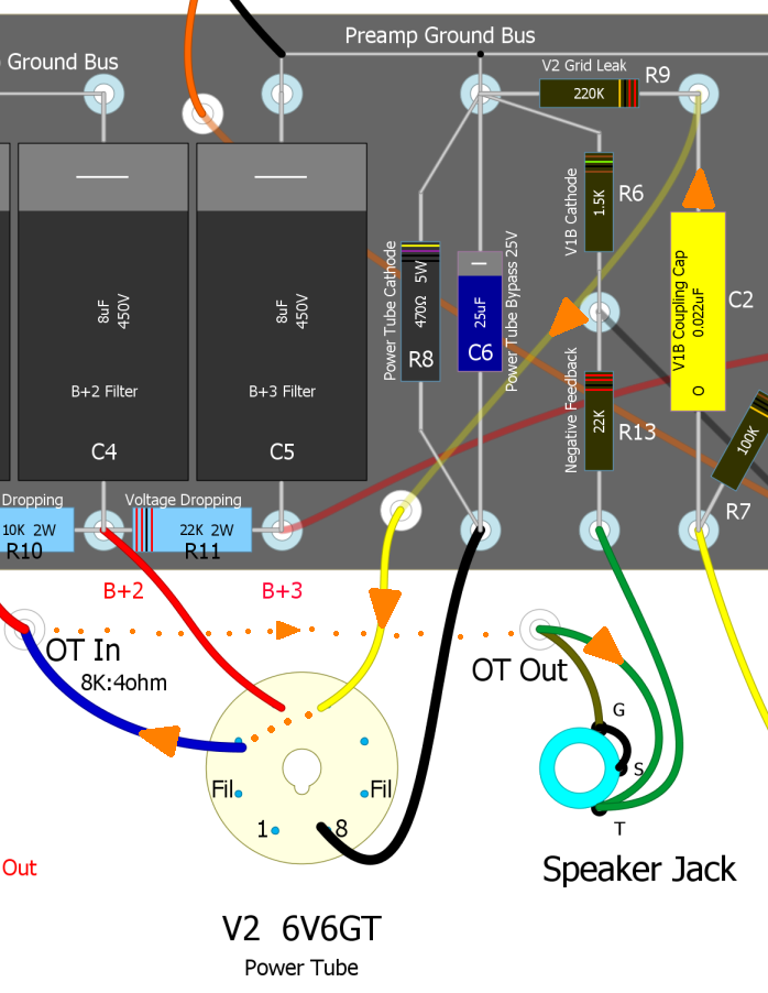
The B+ DC voltage flows to the output transformer's primary winding and to the circuit board's three large filter/reservoir capacitors, C3, C4 and C5 and two voltage dropping resistors, R10 & R11. These resistors and capacitors form RC (resistance capacitance) low pass filters that take the lumpy, pulsing DC output of the rectifier tube and smooth it out--the smoother the better. Any waves or ripples left over in the DC power would be added to our audio signal and heard as hum in the preamp and power tubes. These big capacitors also function as current reservoirs that help feed the amp during high demand. The hydraulic equivalent of a filter capacitor is a hydraulic accumulator. The '16µF 475V' written on the cap is its rating of 16 micro Farads and 475 volts. The '10K 2W' written on resistor R10 is its rating of 10,000 ohms and 2 watts. Here's an online RC Ripple Filter Calculator.
The voltage dropping resistors separate the amp's power into three power supply nodes, B+1, B+2 and B+3. The 360 volts DC from the rectifier is B+1 then it's stepped down to 325 volts DC (B+2) then to 250 volts DC (B+3). The 360 volts DC B+1 direct from the rectifier is fed to the output transformer's primary input which flows on to the power tube plates. The 325 volts DC B+2 is connected to the power tube pin 4--the screen grid. The 250 volts DC B+3 is used to power the preamp tube. The filter capacitors and voltage dropping resistors also decouple the three B+ power nodes to prevent interaction, feedback and oscillation between the preamp stages and power tube. With no guitar signal present the 'idle' voltage at the V1 preamp tube's plate pins 1 and 6 will be around 170 volts DC after flowing through the Load Resistors R5 and R7.
How Chokes Work
Although the Champ does not use a choke many amps do use them to filter the power supply. Typically the choke is placed between the power tube plate and power tube screen power nodes. This is done as a cost savings measure. A choke would have to be very large and expensive to filter the entire power supply for a 50 or 100 watt amplifier.
When electrical current flows through a wire it creates a magnetic field around the wire. Chokes are inductors that use this magnetic field to reduce changes in voltage and current. When no current flows through a wire (you can have voltage but no current) there is no magnetic field generated around the wire. When current increases some of the current will be used to grow a magnetic field around the wire. When current decreases the magnetic field shrinks and the magnetic energy is converted into electrical current. These inductor properties "fight" current changes.
A choke is simply one long wire wound in many loops. A choke will have two leads which are simply the two ends of the one long wire. The wire is usually looped around an iron core which makes it work better. Looping the wire increases the effect of the induced magnetic field ("inductor" comes from the word "induced").
When power supply voltage ripple flows through a choke, the choke "fights" the ripple. As ripple voltage increases, ripple current increases through the choke. The choke will convert some of the current increase into a magnetic field. The choke's magnetic field is stored energy. As the power supply ripple voltage decreases the choke's magnetic field collapses and converts into current. So increasing voltage and current are cut, and decreasing voltage and current are reinforced which reduces the amplitude of voltage ripple.
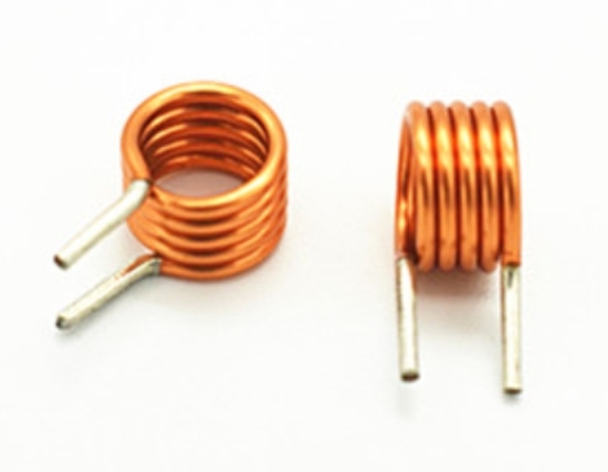
This simple looped wire is a small air core inductor.
Inductors in AC circuits work the same way. Inductance "fights" changes in current and AC audio signals are made up of voltage and current changes. A small inductor can remove high frequencies. A larger value inductor can remove medium and high frequencies. A very high value inductor, like the choke in power supplies, can remove all audio frequencies.
Amp Total Power Usage
How is it that the 5F1 Champ uses 0.75 amps of 6.3 volt current, 2 amps of 5 volt current and 42ma of high voltage current and yet it uses a 2 amp fuse? It's due to power conversion.
This is the power conversion for the 5F1 Champ
First we will convert the current from amps to watts:
The Champ's 5Y3 rectifier tube datasheet shows it uses 2 amps of 5v heater current: 2a x 5v = 10 watts (this is also be called 10 VA)
The 6V6GT power tube datasheet shows it 0.45 amps of 6.3v heater current: 0.45a x 6.3v = 2.835 watts
The 12AX7 datasheet shows it uses 0.3 amps of 6.3v heater current: 0.3a x 6.3v = 1.89 watts
The amp uses 42ma of high voltage DC.
We have a typical 19v drop across the 470 ohm power tube cathode resistor: 19v / 470 = 40ma
We have a 1.5v drop across both of the 12AX7 cathode resistors: 1.5v / 1.5k = 1ma each, 2ma total
42ma x 370v = 15.5 watts
Total the watts: 10w + 2.835w + 1.89w + 15.5w = 30.225 watts of power used by the power transformer secondaries.
Now we convert the secondary watts to primary watts:
If our mains voltage is 125 volts then 30.225w / 125v = 0.24 amps of mains current. We can estimate that the transformer looses about 10% for a total of 0.26 amps, so a 2 amp fuse has a lot of headroom for turn-on power surge.
If our mains voltage is 240 volts then 30.225w / 240v = 0.13 amps + 0.01 amp efficiency loss for a total of 0.14 amps, so a 1 amp fuse could be used.
Well that's it for the 5F1 Champ. It's a great sounding but simple guitar amp. The signal flow is very similar to most other Fender amps, they just have more parts. Really understanding the 5F1 will help you understand other more complex amps.
Fender Original 5F1 Layout and Schematic
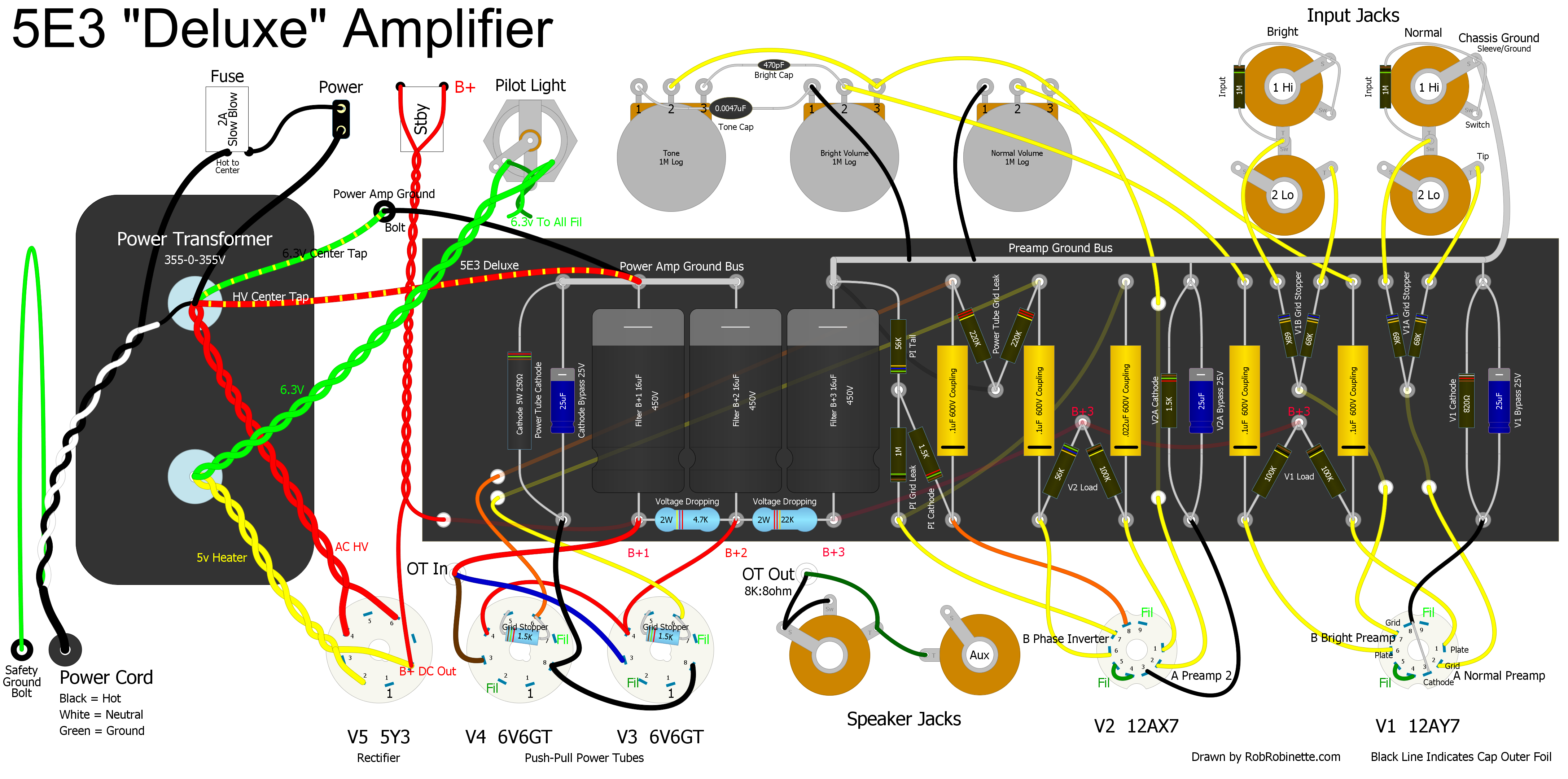
5E3 Tweed Deluxe Annotated Schematic
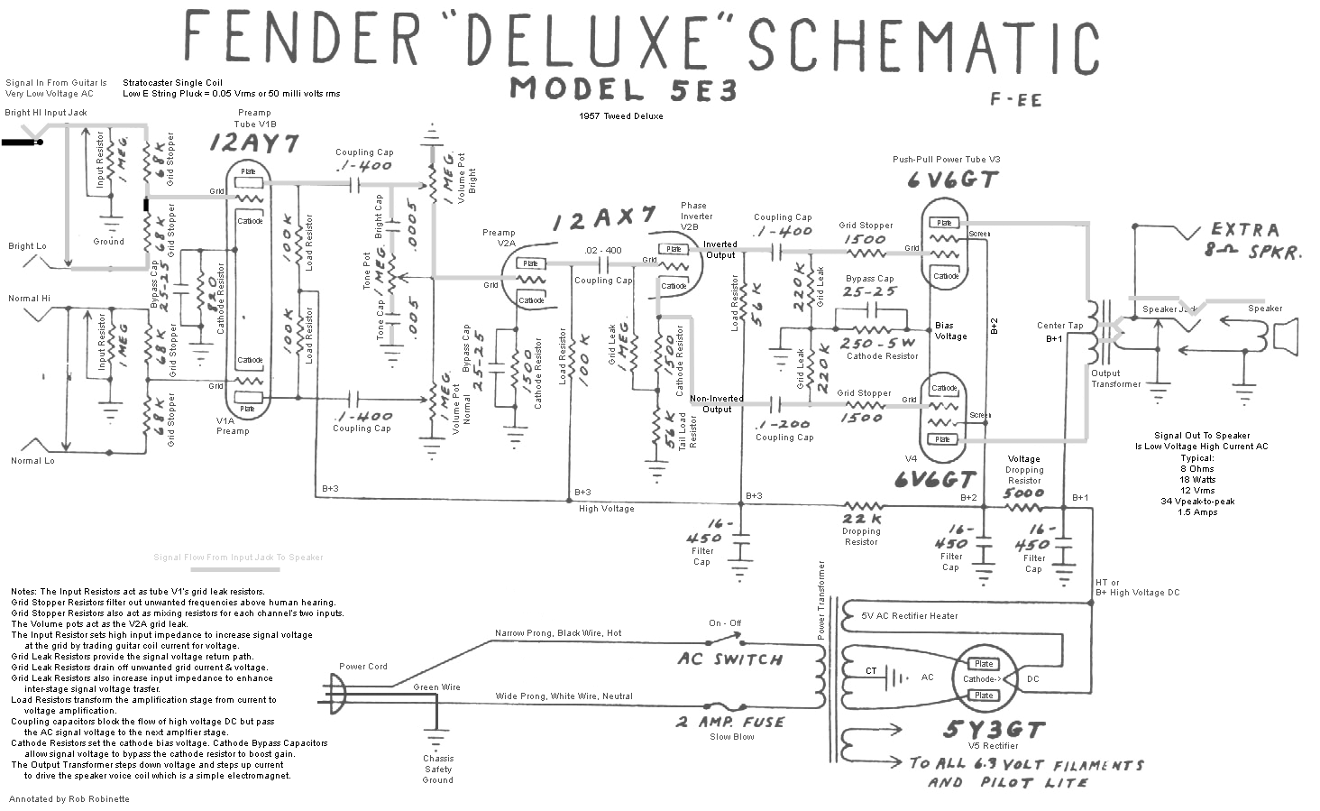
The 5E3 Deluxe is the most common tube amp kit available. It uses two 6V6GT power tubes in a Class AB push-pull configuration. Click the image to view the full size (readable) annotated schematic.
5E3 Layout with Signal Flow and Annotations
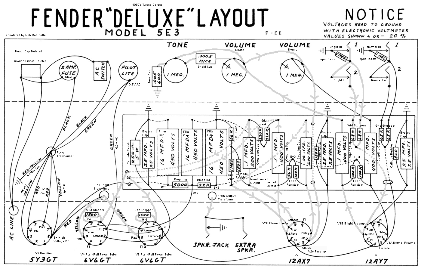
Notice how convoluted the signal path is compared to the schematic. Input jacks are at top right and the speaker jack is bottom center. Click the image to view the full size (readable) annotated layout.
The Pinnacle of tweed Amps, the 1959 5F6-A Bassman with Annotations
My 5F6-A Bassman amp is the sweetest amp I have ever heard. See this for an explanation of How the Bassman Works.
Bonus Info: How Fender multiple guitar input jacks and channel jumpering works
A Note On Amplifier Gain
The more gain an amplifier offers up the more likely it is to oscillate and hum. That's why many high gain amps have "extra" high frequency filtering plate load bypass caps, DC preamp heater voltage, shielded signal cable and "stability" caps across the phase inverter plates. Component placement, lead dress (wire length and placement) and power filtering all become more critical. Higher gain amps can take what would be an acceptable level of noise and amplify it to the point the amp is unusable. If you build a high gain kit amp you can expect to spend some time troubleshooting hum and noise issues until you get the kinks out--you've really got to pay attention to lead dress, especially around the first couple of gain stages.
Tube Bias Circuits
5F1 Cathode Bias
The 5F1's V1 and V2 use "common cathode biasing", also referred to as "self biasing" or just "cathode biased." V1A's bias voltage is set by cathode resistor R4 which is connected to V1A's cathode (pin 3). V1B's bias is set by R6. V2's bias is set by R8. Capacitor C6 is a cathode bypass cap that helps decrease local feedback and increase V2's gain. Although not shown on the original 5F1 Champ Fender schematic and layout, most Champs came from the factory with the C7 cathode bypass capacitor shown at extreme right. The bypass cap boosted the amp's gain. For Champs without the C7 bypass cap adding one is a common and recommended modification.
For the tube's control grid to control the flow of electrons between the cathode and plate there must be a voltage difference between the cathode and control grid. The voltage difference is what repels the electrons to control their flow. The cathode is 'boiling off' negatively charged electrons and a more negatively charged control grid can keep them in place because like charges repel. This voltage difference between the cathode and control grid is called tube 'bias.' Common cathode tubes use the voltage drop across a cathode resistor placed between the cathode and ground to generate the bias voltage.
The much more powerful 5E3P amplifier shown below uses an "adjustable fixed bias" system to supply the bias voltage. It is called "fixed bias" because a steady bias voltage is applied to the tube control grid. A cathode biased amp's bias voltage will fluctuate with the input signal (it's not fixed). A fixed bias amp applies a negative voltage (usually between -35 to -50 volts DC) to the power tubes' control grids and the cathodes are connected directly to ground at zero volts (there is no cathode resistor). Power tubes have a maximum heat dissipation rating given in watts. Exceed this limit and you can melt the tube. Setting a tube's bias for a higher % of maximum dissipation is considered a hotter bias. The power tube grid voltage is always negative on fixed bias amps and a hotter bias will have the grid voltage closer to zero. A hot bias for the 5F6A Bassman would be around -44V DC. Setting a lower % of max dissipation is considered a cooler bias and the grid voltage will be a larger negative number like -50V. See this for info on How to Measure and Adjust Bias.
Adjustable Fixed Bias System
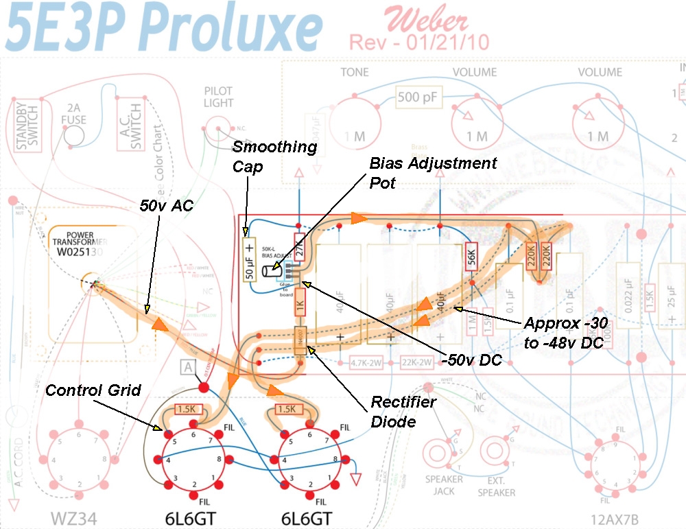
Power Transformer on left supplies 50 volts AC to the Rectifier Diode. The AC power flows into the diode's negative terminal (cathode) so 50 volts of pulsing negative DC flows out. The 1K resistor and large 50uF Filter Capacitor form an RC (resistance capacitance) low pass filter to smooth out the DC pulses. The Bias Adjustment Pot adjusts the amount of negative DC voltage that flows to the Power Tubes' Control Grids. The 27K resistor sets the maximum hot bias, reduce it for hotter max bias, increase it for cooler.
Voltage Gain Through a Tube Guitar Amp
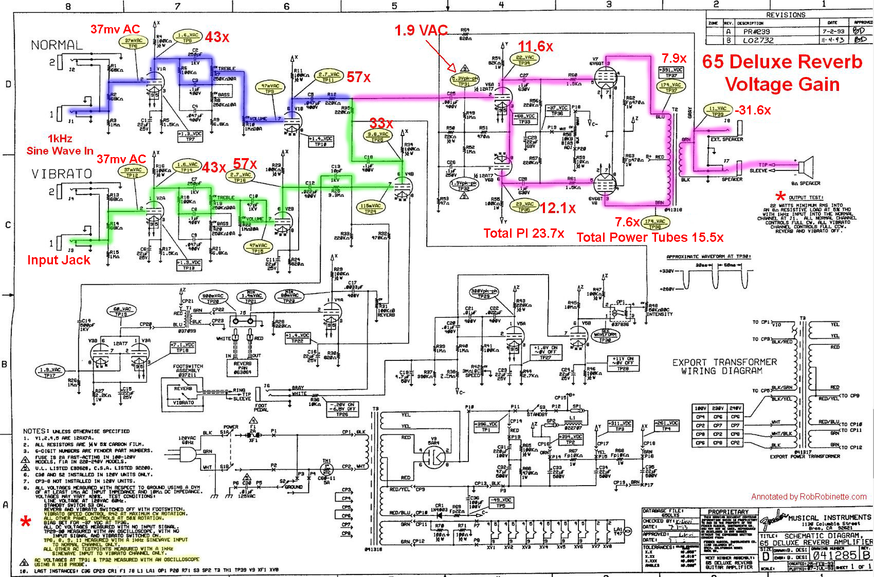
A 1kHz 37 millivolt sine wave (AC) audio signal is injected at a 65 Deluxe Reverb Normal and Vibrato channels' Hi input jack (upper left) with all the volume and tone pots set to a half turn. The 1kHz audio signal path through the amp is highlighted and each stage's gain factor is shown in red with an "x". Yellow ovals list the audio signal voltage.
The 1kHz AC sine wave test signal measures 37 millivolts AC RMS (root-mean-square average) at the V1A (Normal channel) and V2A (Vibrato channel) grids.
V1A and V2A amplify the 37mv AC signal on their grids to 1.6 VAC (volts AC) at their plates. This is a voltage increase (voltage gain or gain factor) of 43 times (.037v x 43 = 1.6v).
The tone stack and volume control load the AC signal down from 1.6 VAC at the V1A and V2A plates to 47mv AC at the V1B and V2B grids. V1B and V2B amplify the 47mv signal 57 times to 2.7 VAC (gain factor of 57).
The Vibrato channel's signal off the V2B plate is attenuated by the reverb circuit from 2.7 VAC down to 115 millivolts AC at the V4B grid. V4B amplifies the Vibrato channel signal 33 times. One explanation for the lower gain factor of this stage is the load applied to the plate from the tremolo circuit. Disconnecting this load with a "tremolo off" mod will significantly boost the Vibrato channel's gain.
We can see the extra gain provided by the Vibrato channel when we compare the 3.8 VAC at its 220k mixing resistor with the 2.7 VAC at the Normal channel mixing resistor. The Vibrato channel puts out 47% more gain than the Normal channel at this volume setting due to the extra V4B gain stage.
The schematic shows 5.3 peak-to-peak volts on the V6A upper phase inverter grid. 5.3vpp equals 1.9 VAC RMS (assumes an undistorted sine wave).
With 1.9 VAC on the phase inverter upper grid and an output at the plate of 22 VAC we get an 11.6x gain. The phase inverter lower triode (V6B) plate is at 23 VAC for a 12.1x gain. Note the 82k plate load resistor on the upper phase inverter triode and 100k on the lower. 82k was used to lower the gain to balance the phase inverter output but 82k is actually a little too low for an exact balance. We can add the two triodes' gain together to get the total phase inverter gain of 23.7x. Note that each phase inverter triode's gain factor is only about 25% of a normal triode gain stage. Also note the audio signal travels from the phase inverter upper triode to the lower triode through their interconnected cathodes. The 1.9 peak-to-peak volt signal shown on the lower phase inverter grid is the negative feedback signal.
While the previous gain stages are voltage amplifiers the power tubes amplify power, meaning voltage and current. The schematic doesn't show power tube grid voltage so we'll ignore the signal loss caused by the 220k grid leak resistors and assume 22 and 23 VAC on the power tube grids for a 7.9 and 7.6x gains to 174 VAC. Each power tube puts out 174 VAC between one half of the transformer primary to the center tap so there is 348 VAC total across the transformer primary so the power tubes' total gain factor is 15.5. Remember the power tubes are amplifying both voltage and current so their contribution to overall gain is higher than the voltage gain number suggests.
The output transformer steps down the 348 VAC primary voltage to 11 VAC at the secondary (and speaker jack) for a -31.6x signal voltage reduction but the signal's current is stepped up by the output transformer 31.6 times (current gain factor of 31.6). The output transformer matches the high impedance audio signal (high voltage but low current) from the power tubes with the low impedance signal (low voltage but high current) needed by the speaker coil.
Vibrato Channel Gain Chain
37mv audio signal in -> V2A 43x -> V2B 57x -> V4B 33x -> Phase Inverter 23.7x -> Power Tubes 15.5x -> Output Transformer -31.6x -> 11 VAC out
With the volume pots set at 1/2 we get 11 VAC into an 8 ohm speaker which yields 15 watts. The amp is rated at 22 watts with 5% total harmonic distortion with the Normal channel volume pot at max.
Note the gain factors of each stage are not additive because there are signal voltage losses between gain stages. If there were no losses between stages in the Vibrato channel and no loss to overdrive a 37mv signal into the amp would yield 65.5 VAC and 536 watts at the speaker jack!
All About Rectifier Circuits
Amplifier rectifiers can use tubes or solid state diodes to rectify alternating current (AC) into direct current (DC). They do this by acting as one-way valves that only allow electrons to flow in one direction.
Solid state rectifiers (silicone diodes) are known as sounding stiff and punchy because they don't create as much voltage drop and sag as tube rectifiers which can have over 60 volts of voltage drop across them.
Voltage drop is caused by the internal resistance of the power transformer and rectifier. It lowers the amp's B+ voltage and can soften the dynamics of an amplifier where the higher voltage provided by solid state rectifiers can make an amp sound punchier, louder and offer up a tighter lower end and overdrive tone. Solid state rectifiers typically drop only 2 volts and a GZ34 tube rectifier drops around 15. The 5Y3 offers up 60 volts of drop.
Voltage sag is the dynamic voltage drop across the rectifier that increases with current demand and creates output volume compression. Output volume compression occurs because high current demand during loud notes lowers the amps B+ voltage and maximum volume is decreased. Conversely, low demand, quiet passages create less voltage sag and generate greater amplification. This makes loud notes quieter and quiet notes louder which equals compression. Class A and AB amps differ in how much voltage sag is generated. Since Class A amplifiers idle near max current there are less current demand fluctuations and therefore less voltage sag. Voltage drop and sag help contribute to the warm, round, tubey sound of vintage amplifiers. The combination of the 5E3 Deluxe's small power transformer, 5Y3 rectifier tube and Class AB operation lead to metric shit tons of voltage sag.
JJ GZ34S Rectifier Tube
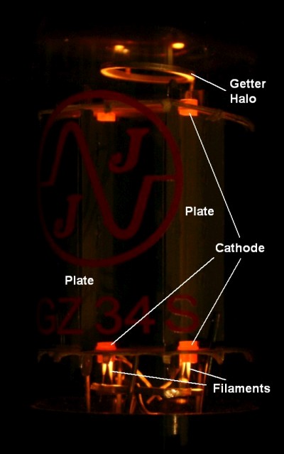
Photo by Rob Robinette.
A single diode or single plate rectifier tube is a half wave rectifier because only half of the AC wave is converted into DC voltage. Many fixed bias power supplies use a single diode half wave rectifier to generate the power tube bias voltage. Silicone diodes are similar to single plate rectifier tubes in that both have one cathode and one anode (plate is another name for a tube's anode). The term "diode" means two electrodes (cathode and anode). Tubes with two electrodes are also called diodes.
Half Wave Rectification In Amp's Bias Circuit
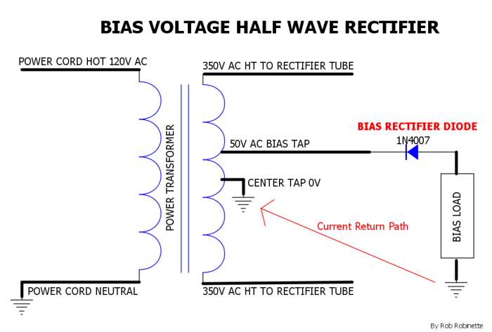
50V AC is tapped off the power transformer and sent to a single diode. It acts as a one-way valve to convert the 60Hz AC into 60Hz pulsing negative DC voltage. The DC out voltage is negative because of the polarity of the diode (turning the diode around would provide positive DC voltage). With the diode's cathode connected to the AC power source, negative DC is created. The bias circuit uses the power transformer's grounded center tap as the current return path.
Half Wave Rectification
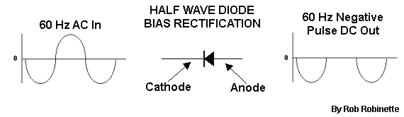
60Hz AC in and 60Hz pulsing negative DC out. Half wave rectification is inefficient because it only converts half of the AC wave. It generates very lumpy DC power which is smoothed using resistors and large capacitors that form a resistance-capacitance (RC) low pass filter.
Two diodes, or a standard dual plate rectifier tube such as the 5Y3 or GZ34, are conventional full wave rectifiers. They are "full wave" rectifiers because both the positive and negative AC wave are converted into DC voltage. Conventional rectifiers require a power transformer center tap to provide a DC current return path from the amp circuit back to the transformer.
Conventional Diode Rectification
![]()
Conventional two diode rectifier showing current flow during the positive half of the AC wave. The power transformer's center tap provides the current return path from the amp circuit back to the transformer. The center tap is grounded at zero volts.
![]()
Conventional rectifier during the negative half of the AC wave.
Conventional Tube Rectification
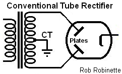
A standard dual plate rectifier tube like the 5Y3 works in exactly the same manner as the above two diode rectifier. That's why tube rectifiers are always paired with power transformers with center taps--the center taps are required to provide a current return path from the amp circuit back to the transformer.
Full Wave Rectification
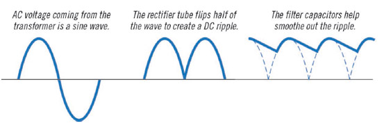
Full Wave Conventional and Bridge rectifiers convert both the positive and negative AC wave (full wave) into DC voltage so they create 120Hz pulsing DC. Compare this graph with the "Half Wave Rectification" graphic above showing 60Hz pulsing DC. Knowing that power line and bias voltage are at 60Hz and high voltage rectified DC is at 120Hz helps with tracking down the source of amplifier hum.
Four diodes can be used to create a full wave bridge rectifier which does not need a power transformer center tap. A bridge rectifier is very efficient and extracts almost twice the voltage from an AC supply as a conventional rectifier.
4 Diode Bridge Rectifier Current Flow During Positive Half of AC Wave
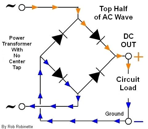
All four diodes in a bridge rectifier act as one-way valves that allow current to flow in only one direction. The two diodes on the left side form the 'bridge' from the amp circuit back to the power transformer so a center tap is not required. As the outflow of current (shown with orange arrows) is 'pushed' by the transformer, the return path (shown with blue arrows) is simultaneously 'pulled' by the transformer's negative voltage so a bridge rectifier can extract twice the voltage of a conventional two diode rectifier which only 'pushes' because the transformer center tap is grounded at zero volts and does not pull.
Bridge Rectifier Current Flow During Negative Half of AC Wave
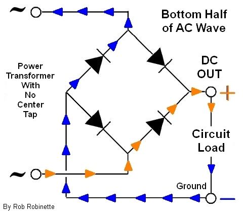
Note: All diagrams in this All About Rectifiers section show conventional current flow when in reality to create a positive voltage electrons must be removed from a conductor (+ voltage = scarcity of electrons, - voltage = excess of electrons).
All rectifiers must have a DC current return path back to the power transformer because the rectified DC flows in only one direction--away from the transformer. The transformer center tap or rectifier bridge provides the current return path back to the transformer.
Although a bridge rectifier will extract twice the voltage from a transformer compared to a conventional rectifier, a bridge rectifier will only supply 62% the rated current at that higher voltage. If you tape off the center tap of a power transformer and replace a conventional rectifier with a bridge rectifier it will generate twice the voltage but the winding wires would have to be of a heavier gauge to generate the same current.
Predict Amp Idle DC Voltage
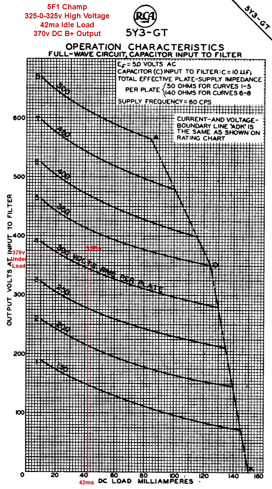
This chart is from the 5Y3 tube rectifier datasheet and shows predicted DC voltage when using a B+ filter cap (there is another chart for chokes). If we know the power transformer high voltage output and the amp's DC current draw the chart will show the rectifier B+ output voltage. The 5F1 Champ uses 42 milliamps of DC current and a 325-0-325v high voltage secondary so we enter the chart at the bottom at 42ma and go up to find the 325v chart curve and move left to find the rectifier output DC volts under load of 370 volts. The no-load B+ voltage is equal to the high voltage secondary peak voltage: 325v * 1.41 = 458 peak volts (1.41 is equal to the square root of 2) so with the power and preamp tubes pulled (no load on the rectifier) you would expect to measure 458 volts DC at the first filter cap.
Concise Rectifier Design Guide by Hammond
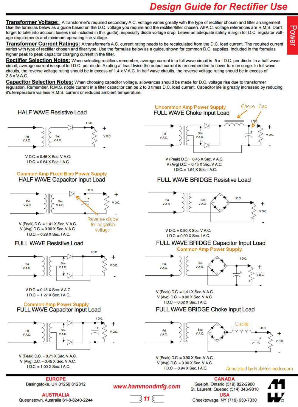
Note the FULL WAVE Capacitor Input Load at bottom left and FULL WAVE BRIDGE Capacitor Input Load at mid right. These are the two most common designs for tube amplifiers. Pri VAC & Sec VAC = Primary & Secondary volts AC RMS.
Why Center Tapped Transformers Don't Need a Bridge Rectifier
This bothered me for a long time until I did enough research to understand the current flow through 2 diode (conventional) and 4 diode (bridge) rectifiers.
Why does a power transformer with a center tap allow rectification with just two diodes versus four needed with no center tap? Because the transformer center tap provides the path for returning current to the transformer. If you use a transformer without a center tap then a 4 diode bridge rectifier is needed to provide the DC current return path from the amp circuit back to the transformer.
Conventional Rectifier and No Center Tap
![]()
With no center tap there's no return path to the transformer so this will not work.
Hybrid Rectifier With No Center Tap
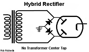
To use a transformer with no center tap with a tube rectifier you can install the 'bridge half' of a bridge rectifier to provide a current return path. Two 1N4007 diodes running from the tube plate pins to ground will do the trick. Diode polarity is important, install the diodes with their stripes (cathodes) to the tube plates.
Hybrid Rectifier With No Center Tap + Backup Diodes
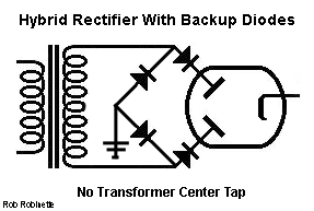
The two diodes connected to the tube plates are soft fail protection 'backup' diodes that will prevent AC from entering the amp if the tube fails as a short circuit. This is the equivalent of a bridge rectifier feeding a tube rectifier.
The 6.3v filament heater circuit is different from the high voltage circuit in that the 6.3v circuit can function fine without a center tap. The 6.3v center tap is not used as a current return path, its only used as a zero volt reference to balance the voltage of the two heater wires and set a stable voltage difference between the heaters and tube cathodes. Keeping the two heater wire voltages the same helps with twisted wire hum cancellation. Since the heater circuit is AC and is not converted to DC both 6.3v wires act as "send" and "return" wires. In these purely AC wires the electrons flow back and forth in both lines so a separate return line isn't needed.
Amplifier Grounding Schemes
The key to understanding grounding schemes is to realize the ground is the source for all the DC electrons flowing through the amp. That's right, the power supply pumps electrons out of the amp circuit creating a scarcity of electrons we measure as a positive voltage. Electrons are pulled out of the ground to replace the ones removed by the power supply. Conventionally we think of DC current flowing from the power supply through the circuit to ground but in actuality the DC electrons are flowing the opposite direction. For amp's using a conventional rectifier the DC current must return to the power transformer center tap. For amps using a bridge rectifier the current must return to the rectifier bridge (see the Rectifier section for more detail on this).
Arrows show flow of ground current back to the power transformer center tap.
The Split Grounding Bus Bar
Splitting the power amp and preamp grounds is currently (no pun intended) the most popular grounding scheme used by amateur amp builders. By far most of the amp's B+ current is used up by the power tube plates so we want a nice "loop" from power transformer, to rectifier, to B+1 filter cap, through the output transformer to power tube plates, to power tube cathode & resistor and back to the power transformer through its center tap. That loop needs a ground reference connection to reduce hum so we bolt the center tap to the chassis but no current should flow into the chassis--it flows through the loop from the transformer, through the amp circuit and back to the transformer.
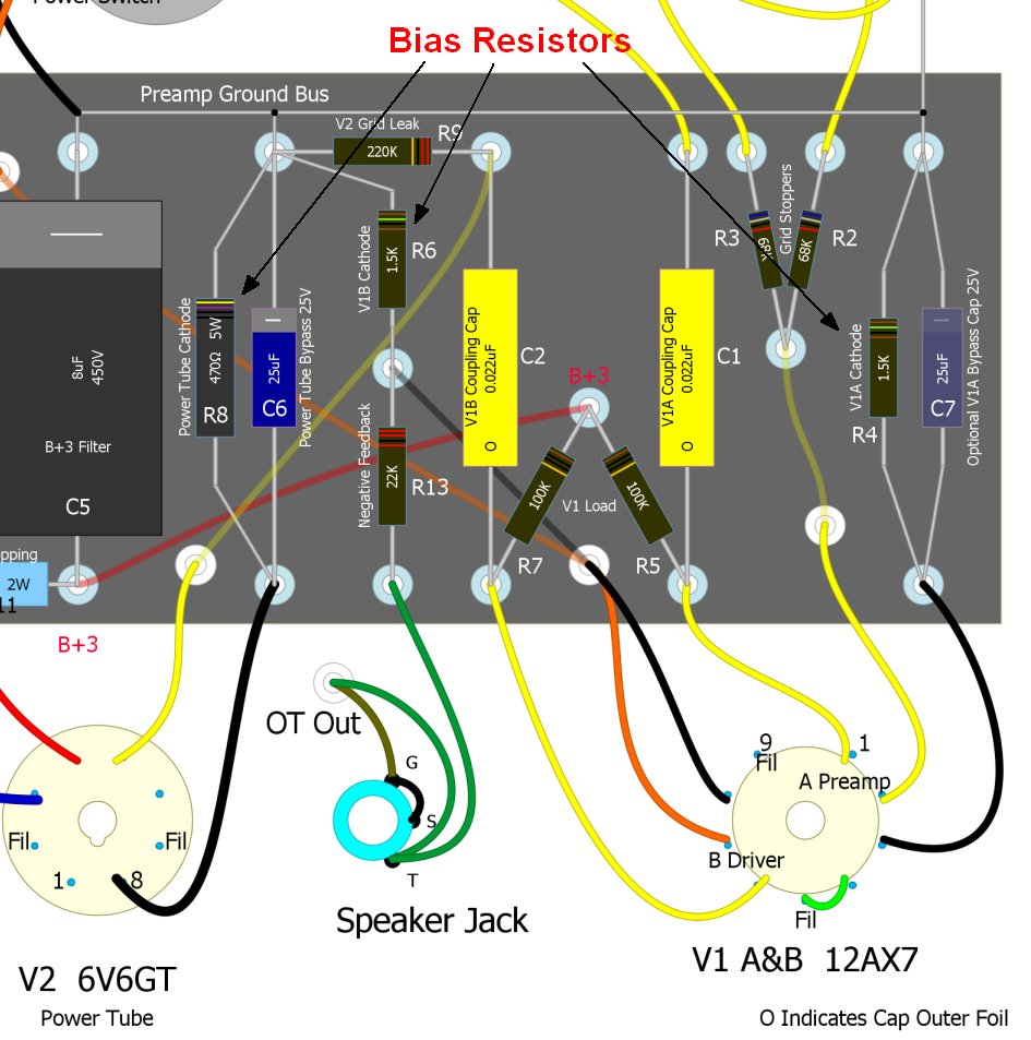
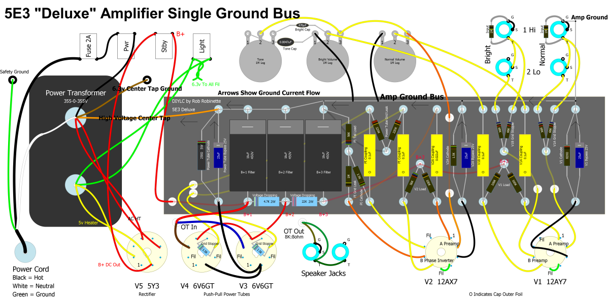
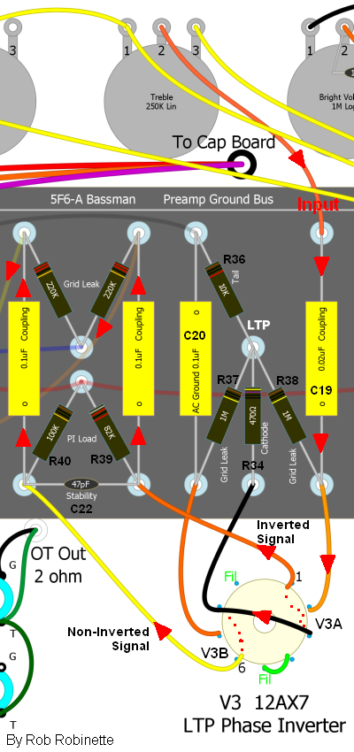
Note the split "Power Amp Ground Bus" and "Preamp Ground Bus" running along the top of the circuit board in this 5E3 Deluxe layout. The power amp is connected to the chassis to the right and above the power transformer. The preamp is connected to the chassis at the upper right input jack.
Since the power tube screens are part of the power amp we usually connect the B+2 (power tube screens) filter cap to the same power amp chassis ground point--but again the current is flowing in a loop through the screen resistors back to the power transformer.
The B+3 (preamp) filter cap provides power to the rest of the amp and its current must also make its way back to the power transformer center tap by way of the ground connection at the input jack. So the preamp's DC current must flow through the chassis from the input jack to the power transformer's center tap. We do it this way to try to prevent interaction between the high current power amp and low current preamp but eddy currents in the steel or aluminum chassis can add noise and hum. Electrical engineers will tell you that flowing ground current through the chassis is a bad idea. I agree but this split bus works fine in low gain amplifiers like the Fender Tweed, blackface and silverface amps.
Actual DC Electron Flow Through the 5E3
The actual flow of electrons is opposite the direction of conventional current because Benjamin Franklin guessed wrong on the direction of electrical flow.
Gray arrows show the actual DC electron flow through the amp (flows negative to positive) which is opposite of "conventional" current direction. Electrons flow from the power transformer center tap to chassis ground to all the tube cathodes. DC electron flow is very slow and takes about 170 hours to make a 600 inch loop around an amp circuit which includes half the length of the power transformer secondary winding and half of the output transformer primary due to their center taps. Don't believe this? See electron drift velocity for more info.
Actual DC Electron Flow With Single Point Bus Ground
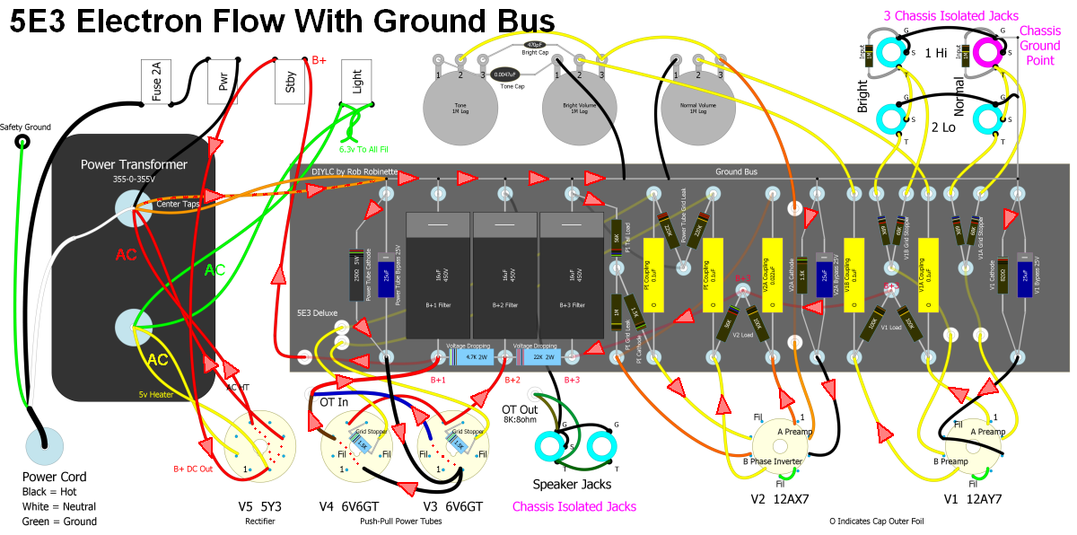
This single point ground bus is only grounded at the upper right input jack. The other three input jacks and speaker jacks must be isolated from the chassis and connected to the ground bus. DC electrons flow in a circular motion starting at the power transformer center tap around the amp.
Electron flow starts with the black Hot and white Neutral power cord wires at far left. Electrons alternate moving back and forth under AC voltage. They really don't move so much as vibrate or wiggle because they only move about .00001 inch each AC cycle. These wiggling electrons in the power transformer primary winding induce AC electron wiggle in the transformer secondary. The high AC voltage from the power transformer secondary tries to push and pull electrons to the rectifier tube but the rectifier acts as a one-way valve that only allows the wiggling electrons to move in one direction so electrons are pulled out of the rectifier's cathode into the transformer.
So the transformer and rectifier act as an electron pump that pulls electrons out of the B+ wire connected to the rectifier's cathode at pin 8. Pulling electrons out of the B+ wire creates a positive DC voltage (scarcity of electrons = positive voltage). Although the power transformer puts out an AC voltage, the only current flowing through the high voltage secondary is DC--the electrons flowing from the rectifier to the transformer center tap. For amps with bridge rectifiers, which do not need a transformer center tap, there will be AC current flowing in the high voltage secondary. See the Rectifier section for more info on how conventional and bridge rectifiers work.
The electrons pulled out of the B+ wire flow through the power transformer's high voltage secondary leads and out its grounded center tap to the ground bus bar. The center tap is the source of all DC electrons that flow through the amp (the guitar signal is AC). Most of the amp's electrons will flow from the ground bus through the power tube cathode resistor and on to the power tube cathodes. Then they flow out the plates and through the output transformer primary then to the B+1 power node, standby switch and back to the rectifier tube for a complete "lap" around the amp. During the amp's operation electrons are constantly making this circular trek around the amp. Electrons captured by the power tube screen flow to the B+2 node and on to the rectifier. Electrons also flow through the preamp tubes' cathodes and out their plates to the B+3 wire and back to the rectifier.
Big Picture Amp Power
The electric company's generators (spinning at 60Hz = 60 revolutions per second = 3600 revolutions per minute) push and pull electrons (alternating current or AC) through wires to your wall socket. You connect your amp's power transformer primary winding to the wall socket and electrons are pushed and pulled through the winding. The transformer's iron core captures the magnetic field (flux) generated by the primary winding and induces a stepped up higher voltage AC in the secondary winding. The secondary winding is connected to the 5Y3 rectifier's two plates. Every AC half cycle one plate is charged positive (scarcity of electrons) while the other plate is charged negatively (excess electrons). The negatively charged plate does nothing while the positively charged plate pulls electrons from the cathode and the B+ supply wire attached to it (removing electrons from the B+ wire creates a positive voltage).
During the next AC half cycle voltage on the two plates is reversed. One plate is charged positive and pulls electrons from the cathode while the other plate does nothing. Because the 5Y3 has two plates and pulls electrons during both halves of the AC cycle it is a 'full wave' rectifier and because it only 'pulls' electrons they flow in only one direction which makes the current DC (direct current). A rectifier with just one plate and cathode would only pull electrons during half the AC cycle so it would be a half wave rectifier. The single diode in bias power supplies is a half wave rectifier.
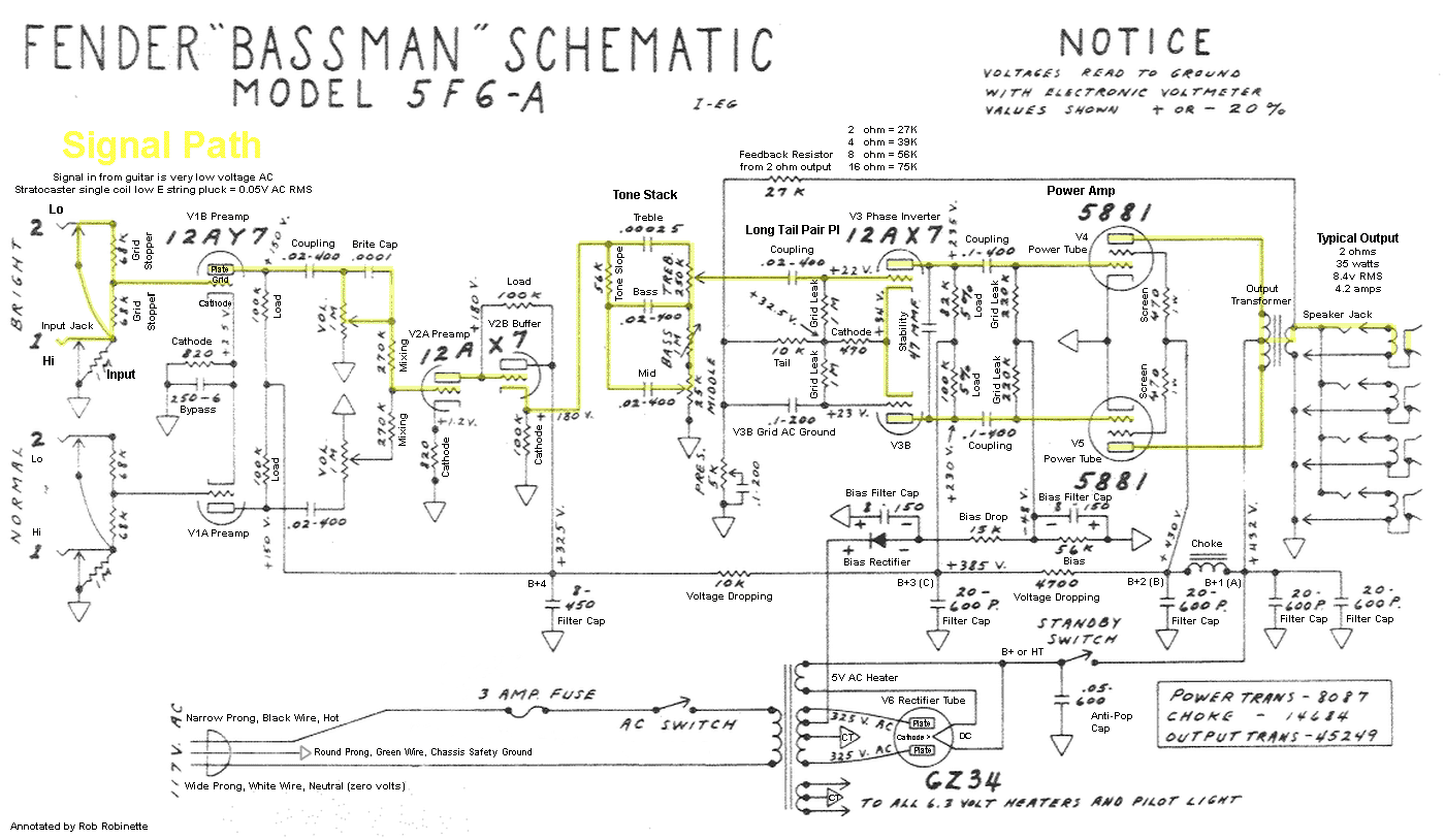
Fender Tweed 1959 5F6-A Bassman Schematic With Signal Path and Component Function
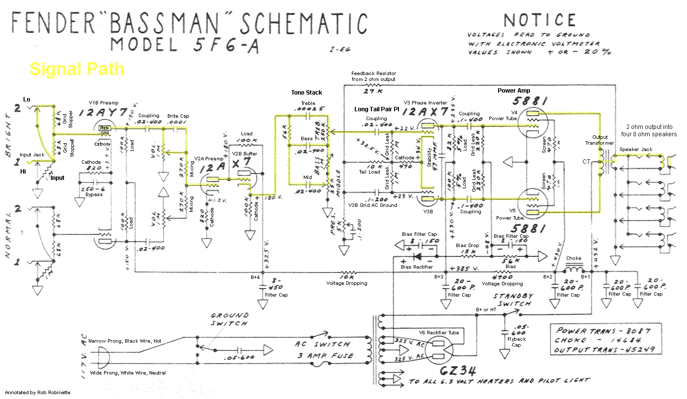
The 5F6A Bassman is a truly classic amp. Major differences from the 5E3 Deluxe include a tone stack with bass, treble and mid controls and a tone stack buffer (V2B) just before the tone stack. The long tail pair phase inverter adds gain and helps drive the big 5881 fixed bias power tubes into full distortion. The amp also came with much larger value filter/reservoir caps to drive the lows from a bass guitar. Click on image to see the full size (readable) graphic.
How Cathode Bypass Capacitors Work
Cathode Bypass Cap C5
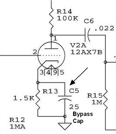
Cap C5 at the bottom center bypasses the R13 cathode resistor.
Adding a bypass capacitor to a tube's cathode resistor is a common way to boost gain. Without a bypass capacitor electrons flow from ground through the R13 cathode resistor to the tube's cathode (3), through the grid (2) and out the plate (1). As electrons are pulled through the cathode resistor a positive voltage is formed on the cathode which is used as the tube's bias voltage. In the circuit above (5E3 Deluxe second gain stage) about 1.7 volts DC will be found on the cathode.
The larger the positive signal voltage is on the grid the larger the flow of electrons through the cathode resistor and therefore the larger the voltage on the cathode. These increases in cathode voltage and therefore bias voltage acts as a negative feedback mechanism because a higher bias voltage leads to a reduction in bias current. This bias voltage fluctuation helps keep the flow of electrons through the tube in check. This is why cathode biased tubes are called "self biasing."
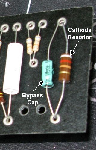
5E3 Deluxe V1A bypass cap.
Adding a bypass capacitor around the cathode resistor reduces this negative feedback because the bypass capacitor acts as an electron reservoir. When the tube's grid goes positive and flows more electrons through the tube it's much easier to pull electrons from the bypass cap reservoir than pull them through the cathode resistor. The freer flow leads to more electrons flowing through the tube so more gain is generated.
When the grid goes negative and slows the flow of electrons through the tube the capacitor is recharged and is ready for the next positive grid electron demand.
How the Bassman's Long Tail Pair Phase Inverter Works
The Long Tail Pair (LTP) Phase Inverter (also called the cathode-coupled phase inverter) is the most popular phase inverter in guitar amplifiers due to its large output voltage swing and sweet overdrive tone. Unlike the non-amplifying cathodyne phase inverter in the 5E3 Deluxe the LTP phase inverter not only creates a dual mirror image signal stream but it also acts as a gain stage boosting the signal by about 1/4 of what two normal triode gain stages would. This added gain gives its output more voltage swing to drive big bottle power tubes to a fully distorted state. The LTP is a true differential amplifier that amplifies the difference between its two grids. It uses both halves of a dual triode tube (usually a 12AX7 or 12AT7).
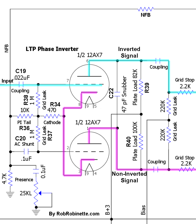
Signal flow shown with red arrows. Component numbers on the schematic and layout match. The signal enters the phase inverter at V3A's grid and flows out both its plate (inverted signal) and cathode (non-inverted signal). The cathode signal flows to V3B's cathode where it is amplified.
For simplicity I will refer to the upper V3A triode as the "upper triode" and V3B as the "lower."
The upper triode in the schematic above has a dual function. It acts as a normal gain stage by outputting an inverted signal at its plate but also acts like a cathode follower by outputting a non-inverted signal at its cathode.
In the schematic above the AC input signal flows through coupling capacitor C19. Cap C19 blocks the upper triode's 32.5v of DC grid voltage out of the tone stack. The signal then flows onto the upper grid while the lower grid is held at a constant DC voltage and all AC signal is sent to ground through shunt capacitor C20. C20 also passes the negative feedback signal to the lower triode grid. C20's third function is to act as a coupling cap to handle the DC voltage across the R36 tail resistor.
The upper and lower cathodes are tied together. All of the lower triode's input signal flows from the upper cathode. With the lower grid held constant, signal voltage fluctuations on the lower cathode alter the electron flow from it to the plate which creates an amplified signal on the lower triode plate.
R36 is the tail resistor that creates the relatively high voltage (34v DC in the Bassman) needed for the cathode follower function of the upper cathode. It also supplies a near constant current flow shared between the two cathodes--as current increases through the upper cathode the current decreases through the lower and vice versa.
R34 is a standard bias resistor and creates a 1.5 volt difference between both tubes' grid and cathode.
R37 and R38 are simply grid leak resistors which leak off DC grid current to maintain a steady DC bias voltage between the grid and cathode.
The plate load resistors R39 and R40 are different values to balance the difference in gain between the upper and lower triodes.
The negative feedback signal from the output transformer's 2 ohm speaker tap is injected into the LTP phase inverter in two places: the lower grid through C20 and at the R36 tail resistor which leads to the cathode. The negative feedback signal on the lower grid is in phase with the primary signal on the upper grid and counteracts the signal resulting in negative feedback attenuation. Injecting the NFB signal at the tail resistor helps balance the feedback effect on the upper and lower plates.
The Presence control (R35 and C21) removes a variable amount of high frequency from the negative feedback signal. Reducing negative feedback has the effect of boosting output so reducing the high frequencies in the negative feedback signal boosts high frequency output. C21 shunts high frequency AC NFB signal voltage to ground. Increasing C21's capacitance value will lower the cutoff frequency and bypass a larger range of frequencies to ground therefore boosting a larger frequency range at the speaker output.
Capacitor C22 suppresses oscillations above audio frequencies between the two triodes' plates to help stabilize the circuit.
LTP and cathodyne phase inverters present a very high impedance to upstream circuits because their grid leak resistors are "bootstrapped" to the phase inverter tail resistor. The input signal on the grid is also present at the top of the tail resistor. This in-phase tail resistor signal reduces signal loss through the grid leak resistor which greatly reduces the load shown to the previous gain stage. Since impedance affects an audio filter's corner frequency we must use a much smaller coupling cap at the phase inverter grid to get the same low frequency roll off. This is why phase inverter input coupling caps are so small. AB763 blackface head cab amps use a 500pF coupling cap and the .022uF cap used by Marshall in their Plexi and JCM800 could easily be reduced to .002uF with no effect on tone but decrease the likelihood of blocking distortion.
Function Detail: When a positive voltage signal arrives at the upper grid the reduction of blocking negative electrons on the grid allows electrons to flow from its cathode, through the grid, to its plate. The electrons flowing onto the plate lowers the plate voltage--this is the inverted and amplified output signal. As electrons leave the upper cathode a positive voltage is created on the cathode (scarcity of electrons = positive voltage) caused by the voltage drop across the cathode resistor R34. This positive signal voltage is also present in the lower cathode because the two cathodes are directly connected. Since the lower grid is held constant at 0 volts AC, any change in its cathode voltage will create a voltage difference between the grid and cathode. This voltage difference changes the flow of electrons from the cathode, through the grid to the plate. As the lower cathode goes positive (scarcity of electrons) fewer electrons will flow from it through the grid to the plate. The reduction of electrons flowing onto the plate raises the plate voltage--this is the non-inverted and amplified output signal.
Bassman 5F6-A LTP PI Voltages
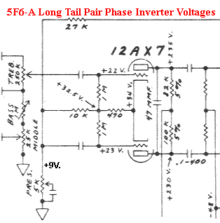
Note the voltage difference between the tail resistor junction of 32.5v and the cathodes at 34v equaling a normal bias for a 12AX7 of 1.5v. The voltage difference between the grids (22 and 23v) and the resistor intersection (32.5v) is measurement error caused by voltage probe circuit loading. If the voltage difference were real the tube would be in cutoff.
How Ultra-Linear Output Transformers Work
If you power the power tube screen grids (g2) from the output transformer center tap (B+) the tubes function as normal pentodes since the screen voltage will be fixed at or near B+.
But if you power the screens with the ends of the output transformer winding (same voltage as the power tube plates) the tube functions as a triode because the plates' and screens' voltage will fluctuate together.
An ultra-linear output transformer has two extra tap wires that power the power tube screen grids. The ultra-linear transformer taps are part way between the center tap and winding ends so the power tubes function as a triode-pentode hybrid. The screen voltage will fluctuate with the plates but with much less amplitude. This results in more linear amplification (less clean signal distortion) and is used extensively in stereo audio tube amplifiers.
Ultra-linear is such a fundamental change to how a power tube operates that it does affect both the amp's clean and overdrive tone. Some Fender silver face amps use ultra-linear and they tend to be loud, clean and excellent pedal platforms.
This diagram from Richard Kuehnel's Vacuum Tube Circuit Design: Guitar Amplifier Power Amps shows the ultra-linear taps connected to the power tube screens:
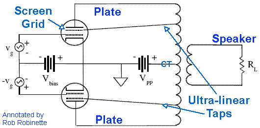
The problem is ultra-linear operation reduces power tube distortion which usually sounds better than preamp distortion. This shifts the balance of preamp and poweramp distortion toward the preamp which is just not a good thing.
You can simply ignore the ultra-linear taps on an output transformer by disconnecting and insulating them and then powering the screen grids like normal guitar amps with an RC filter or choke between the center tap power node and screen grid node.
You can also put the screen grid connection on a switch and power them from either the ultra-linear taps or from their own power node. Use ultra-linear mode for clean headroom and to handle high output effects pedals and use the normal mode for sweet power tube distortion.
Impedance
Understanding impedance was one of the last things I figured out about guitar and amp electronics.
Impedance, whose symbol is Z, is only a factor in alternating current (AC) circuits so in a guitar amplifier impedance applies to the guitar audio signal voltage and not so much to the DC power supply.
Impedance is made up of three things that impede or restrict AC current flow: resistance, inductance and capacitance but its easier if you just think of impedance as "AC resistance." We'll leave inductance and capacitance to the end of this discussion to simplify things. The term "impedance" can apply to both signals and circuits.
A high impedance signal has relatively high voltage but low current so the signal is "thin."
A low impedance signal has relatively low voltage but lots of current so the signal is "thick." There's more current backing up the signal voltage.
A high impedance circuit is a low load circuit that restricts AC current flow.
A low impedance circuit is a heavy load circuit that allows AC current to flow easily.
I like to think of a low impedance signal as a slow moving, deep river and a high impedance signal as a shallow, fast moving stream. I also visualize a high impedance signal as "thin" and a low impedance signal as being "thick."
A thin signal is more likely to lose it's high end when it encounters resistors, capacitors and inductors.
Let's take a look at a guitar circuit:
Simple Guitar Circuit
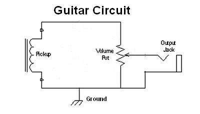
The Pickup on the left generates the guitar signal. The Volume Pot bleeds guitar signal to ground to lower the guitar's output volume. A typical guitar has an impedance of 10k to 20k ohms.
In the circuit below we short the guitar output jack and turn the volume pot all the way up so there's very little to restrict electron flow from one pickup coil wire, around the circuit and back to the pickup. This is a very low impedance circuit with lots of current flow and little restriction to generate electron pressure or voltage:
Low Impedance Circuit
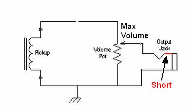
Electrons easily flow from the pickup coil, around the circuit, back to the pickup so we have high current and low voltage. The guitar's AC output audio signal will have very little voltage but lots of current will flow which makes this a low impedance circuit and a low impedance signal.
In the circuit below we turn the volume pot all the way down so the electron flow from the pickup has to flow through the volume pot's 500 kilohms of resistance. The circuit is now a high impedance circuit. A small amount of current flows because of the volume pot's restriction. This restriction causes the electrons to stack up at the pot which generates electron pressure or voltage across the pot:
High Impedance Circuit
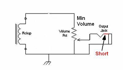
Electrons stack up trying to flow through the volume pot's 500k of resistance which reduces current but increases the voltage across the volume pot. The guitar's AC audio signal at the pot's input will have high voltage but little current flow which makes it a high impedance circuit and high impedance signal.
You've probably heard how a tone stack can "load down" an upstream preamp circuit. The preamp tube's AC output audio signal is a high impedance signal with lots of voltage swing but very little current driving those voltage swings--I think of it as a "thin" signal. If the following circuit has a low impedance it will "eat up" or load down the audio signal's current. The low impedance circuit allows too much current to sink to ground so the amplitude of the audio signal voltage swings are reduced and attenuated. That's what happens in the tone stack when you turn the tone controls down. The tone stack becomes a low impedance circuit and too much AC signal current can be bled to ground lowering the amp's output volume. Guitar players don't want their volume to change when they change a tone control setting.
As I said in the beginning, impedance is made up of three things that impede or restrict AC current flow: resistance, inductance and capacitance.
Inductance is generated by AC signals flowing through coils so guitar pickups add impedance to the guitar and amp input circuits.
Capacitance in a circuit acts as a drag on AC signals because the signal looses energy moving electrons on and off the opposing capacitor "plate." The "plate" can be the actual plate of a capacitor, the ground shield in a guitar cable or a nearby wire in an amp. There's even capacitance between the electrodes in a tube.
Tube amp gain stages typically put out high impedance signals (high voltage, low current, "thin") but a cathode follower can put out much more current to create a low impedance signal.
Input and Output Impedance Bridging
It took me a long time to understand why input and output impedance matters in amplifier circuits. Here's my layman's explanation:
For simplicity sake you can think of impedance as AC resistance. The maximum power-transfer theorem says to transfer the maximum amount of power from a source (guitar) to a load (amplifier), the load impedance should match the source impedance (a.k.a. Impedance Matching).
Impedance Matching is used for maximum power in the power amp circuit where the power tube output impedance is matched to the speaker impedance through the output transformer. But at the amp's guitar signal input we're not concerned with maximum power transfer, we want maximum voltage transfer because a guitar amplifier amplifies a signal voltage--the voltage changes are the audio signal. We really don't care about the current generated by a guitar's pickup coil, it's the pickup's voltage changes that will be amplified by the preamp tubes. Since we favor voltage over current we can use an impedance mismatch to trade current for voltage. This intentional impedance mismatch reduces the current from the guitar but boosts the signal voltage the amplifier receives.
Guitar Output Impedance & Amplifier Input Impedance
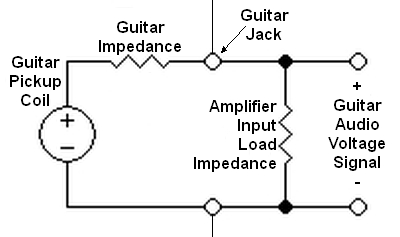
Guitar circuit on left, amplifier input on the right. The current generated by the guitar pickup coil must be allowed to loop back to the guitar pickup. Typical guitar impedance is around 10k to 20k ohms. The "Amplifier Input Load Impedance" is typically a 1 megaohm input resistor mounted on the amp's input jack.
In the diagram above the guitar's pickup coil generates a signal voltage. The guitar's output impedance is made up of the resistance of the pickup coil, volume and tone controls + the guitar circuit's capacitance and inductance. Since we can't control the output impedance of the guitar we can maximize the signal voltage by making the amplifier input impedance as large as possible, preferably 10 or more times greater than the guitar's output impedance (Rule of 10).
A high input impedance reduces the current flowing through the amplifier but increases the signal voltage level. It also reduces distortion because the guitar's coil can output less current. This is called high impedance bridging and is used extensively in electronic audio circuits. The Input Resistor R1 on the 5F1 amplifier's guitar Jack 1 adds input impedance to boost the signal voltage from the guitar.
The same principal applies between amplifier stages. The output stage driver tube V1B sends the guitar signal voltage to the power tube V2. Low output impedance from the driver tube and high input impedance from the power tube boosts the signal voltage. This is what resistor R9 (power tube grid leak) does, it sets a high input impedance to the driver tube V2. Back to Signal Input.
Impedance Mismatch Between the Power Tube and Speaker
As mentioned earlier to get the most power out of the amplifier the power tube and speaker should match their impedance. But what happens when they don't match?
Notice how when plate load resistance (bottom of graph) is increased beyond 4k ohms power output begins to drop off (left side of graph), total distortion increases, 2nd order harmonic distortion increases (2nd H) but nasty sounding 3rd order harmonic distortion (3rd H) increases much more. Also notice how when plate load is decreased power output again decreases, total distortion again increases but sweet sounding 2nd order harmonic distortion increases and and nasty sounding 3rd order decreases. This is why a low impedance mismatch can sound better than a perfect amp-to-speaker impedance match. Also note that when running a 6L6 amp with an 8 ohm output transformer hooked up to a 4 ohm speaker the load resistance is cut in half from 4k to 2k and output power drops from 7.3 watts to 5.6 for a 23% power loss.
High Mismatch
If you connect a 16 ohm speaker to your 8 ohm output transformer (16 ohm load and 100% increase) the impedance as seen by the power tube plate increases and plate current decreases which can lengthen the lifespan of your power tubes, especially in Class A amps. This decrease in plate current will decrease demands on the power transformer and it will run cooler. Power filtering effectiveness is increased as current demand decreases so hum and line noise should decrease, especially in Class A amps. Decreased hum can help prevent ghost notes which are caused by hum interacting with musical notes to create false harmonic tones.
Since the power tube and transformer are not coupled at maximum efficiency some power is turned into transformer heat and the amp's power output is reduced.
We get the opposite of the sonic improvements of a low impedance mismatch: Sweet sounding 2nd order harmonic distortion in the power tube and nasty sounding 3rd harmonic distortion increase but the 3rd harmonic dominates.
The main problems with a high impedance mismatch are increased screen current and flyback voltage generated in the output transformer. A higher plate load impedance can rotate the plate load line to below the knee and cause excessive screen current which can melt the screens and kill the tubes. Flyback voltage can damage the power tubes and the output transformer itself. Flyback voltage spikes can cause the power tube to arc between pins or burn through the thin lacquer wire insulation used in the transformer windings. This is normally not a concern when going "one step" away from a match such as running a 4 ohm output transformer with an 8 ohm speaker unless the output transformer is cheaply made or really old. But running a 4 ohm transformer with a 16 ohm speaker can generate very high flyback voltages when running the amp hard near max volume.
For you Hi-Fi guys, increasing a speaker's impedance will change a passive crossover's crossover frequency. Changing out a two-way speaker's 4 ohm bass driver with an 8 ohm will shift the low pass filter's crossover point higher a full octave which will feed the bass driver more mid freqs and create an overlap where both the tweeter and bass driver are active. The bass driver impedance mismatch won't directly affect the tweeter crossover frequency.
Low Mismatch
If your output transformer is designed to match your power tubes to an 8 ohm speaker and you connect a 4 ohm speaker then the impedance as seen by the power tube plate decreases by 50% too. Less impedance will cause plate current to increase. The power tubes are stressed by this increased plate current so the power tube lifespan can be shortened. This is especially true of Class A amps because they idle near max current flow. Since the plate current idles near maximum, the entire power supply also runs at maximum output so the rectifier tube and power transformer will run hotter. Power filtering effectiveness is reduced as current demand increases so hum and noise may increase, especially in Class A amps. Increased hum can cause ghost notes.
The increase in primary current will cause the output transformer to run hotter. This generation of excess heat reduces power output at the speaker.
Many vintage Fender tube combo amps have an aux speaker jack that's wired in parallel with the built-in speaker. Plugging in a speaker rated at the same ohms as the built-in speaker will cut the speaker load in half for a "one step" low mismatch. Fender designed their output transformers to handle this and is considered safe.
But there are two possible sonic improvements with a power tube and speaker low mismatch. Sweet sounding 2nd order harmonic distortion in the power tube increases and nasty sounding 3rd harmonic distortion decreases dramatically. This is why it's worth experimenting with different speaker loads, you may like the tone you get. This is also why I prefer a 6.6k:8 ohm output transformer for 6V6 power tubes like the Deluxe Reverb uses instead of the typical 6V6 8k:8 ohm transformer.
If your power and/or output transformers run hot with a matched speaker load then mismatching them is more of a risk. The bottom line is the greater the low impedance mismatch, the harder your amp works, and the greater the high impedance mismatch, the more likely you are to burn out your output transformer and/or power tubes. For tube amps a low mismatch is safer than a high mismatch, that's why most speaker jacks have a shorting switch--a short is better than an open circuit. The opposite is generally true for solid state amps--a short will burn out their output transistors. An output transformer open circuit must be avoided, that's why I recommend soldering speaker wire to the speaker and why I recommend you shut down your amp before changing the speaker impedance switch (and avoid cheap impedance switches in your builds).
For two-way Hi-Fi speakers, decreasing a speaker's impedance will change a passive crossover's crossover frequency. Changing out a two-way speaker's 8 ohm bass driver with a 4 ohm will shift the low pass filter's crossover point lower a full octave which will feed the bass driver less mid freqs and create a "hole" in the speaker system's frequency response. The bass driver impedance mismatch won't directly affect the tweeter crossover frequency.
Running 2 Power Tubes in a 4 Power Tube Amp
Many push-pull amps designed to run 4 power tubes can be run with 2 power tubes to cut the output power in half. But since the output transformer was designed to load the current put out by 4 power tubes we need to make an adjustment on the speaker end to load 2 tubes properly. Since 2 power tubes put out half the current of 4 tubes we need to double the speaker impedance so 2 tubes feel the same load as when 4 tubes are used. If your amp is designed to run an 8 ohm speaker with 4 tubes like the AB763 Blackface Single Showman, it will need a 16 ohm speaker when run with 2 power tubes.
Amp and Speaker Phase
Amplifier and speaker phase has to do with which way a speaker moves, in or out, with a positive voltage at the amp input (such as a 1.5v battery + terminal to input jack tip). For multiple speakers playing the same source material such as a stereo audio amp or a multi speaker guitar cab, phase does matter. You want all the speakers moving in concert--all of them moving out together, then in together. If not there will be interactions between the speakers that change the apparent volume of certain frequencies. A loss of low end is usually what is noticed but the volume loss and frequencies depend upon the position of the listener.
For single speaker amps however, phase does not matter. I have had guitar players argue with me that it does matter, especially when they are working with guitar/amp feedback. Why would it matter if the speaker moves outward when the guitar string moves upward versus downward? If the listener (or guitar player if he is working with amp feedback) moves a foot or two toward or away from the amp speaker the phase flips at his location so phase does not matter.
Many multi-channel guitar amplifiers have different phase for different channels. If a channel has 1 or 3 extra gain stages compared to another channel then the amp/speaker phase will be 100% different between those two channels at the speakers. Again, this does not matter due to the material in the previous paragraph. But, if you jumper two out of phase channels they will sound weak and funky due to the phase cancellation when the two channels meet inside the amp.
What about two guitar players playing the exact same song? Does it matter if their two amps and speakers are in phase? No, because their picking would have to be incredibly synchronized to make a difference. At 1000Hz there is three hundredths of a second difference between the signal and 100% out of phase. The placement of the players' amp speakers is also important. A 1000Hz signal has a wavelength of 13.5 inches so if one of the speakers is 6.75 inches closer to the listener the phase will change by 100%. Don't worry about your band mates being out of phase with you or your amp.
Changing an amp's phase can help when recording live performances. Standing acoustic waves can cause tonal anomalies that can sometimes be improved by changing the phase of the guitar or bass amp. The bass amp open E is 41Hz which has a wavelength of 25 feet so flipping the polarity of a bass amp can change a standing pressure wave at the microphone to a standing wave trough which may solve the guitar and bass interaction at the microphone. Live concert sound board operators sometimes run into the same situation. At their location there is a funky interaction and by flipping the phase of the guitar or bass signal using the sound board can improve the tone at his location. The problem is if he moved to a new location he could find another spot with similar funky interaction.
Power Supply Shock Potential
Let's say we take a new 325-0-325v rated power transformer out of the box and connect the primary to 125 volts AC from the wall. The power transformer center tap and high voltage secondary wires aren't connected to anything (they're floating) and we measure 650 volts AC from one high voltage secondary wire to the other. We would also measure around 325 volts AC from either hot wire to the center tap.
We can touch either hot wire or center tap and not get shocked because the voltage isn't referenced to ground--the voltage is only between the three secondary wires. If we measure the voltage between a metal ground rod sunk into the earth and any secondary wire we'll see only random low voltage caused by transformer leakage.
But if we touch any two secondary wires we will get shocked.
If we connect the power transformer center tap to an un-grounded metal chassis we would measure around 325 VAC between either high voltage wire and the chassis but we can still touch a single hot wire or the chassis (not both) and we won't get shocked.
If we ground the chassis we now have a modern, standard, powered amplifier. We and the grounded chassis have a common path literally through the ground. If we touch an amp hot wire electrons can flow between the ground and the hot wire through our body and shock us.
If we rest one hand on the chassis and touch a hot wire with the other then 325 volts AC will push current from one hand to the other across our chest--that's why we have the one-hand rule for working on hot amplifiers.
If we stand on an insulated plastic box so our body has no path to earth we can touch either hot wire and not get shocked.
We can hold the grounded chassis in our hands and connect a hot wire (or failed short capacitor) to the chassis and not get shocked because the lowest impedance path to earth is through the chassis ground wire. Now if we were standing in a pool of water in our basement and did that we would probably feel a tingle.
Early Gibson Gibsonette Amp
The early Gibsonette (mid-late 1940's) has an unusual design. It uses a single pentode (6SJ7 tube) stage for the preamp, a self-split push-pull power amp (2x6V6) which requires no phase inverter. The self-split power amp works like this: The guitar signal on the upper power tube grid changes the current flowing through the tube which causes a voltage drop across the cathode resistor. This voltage drop is also present on the lower power tube cathode and since the lower grid is grounded (common grid) the voltage changes on the cathode affect the current flowing through the lower power tube. The speaker field coil is an electromagnet that takes the place of the speaker permanent magnet. The field coil also acts as the choke.
Gibson GA-40 Version 3
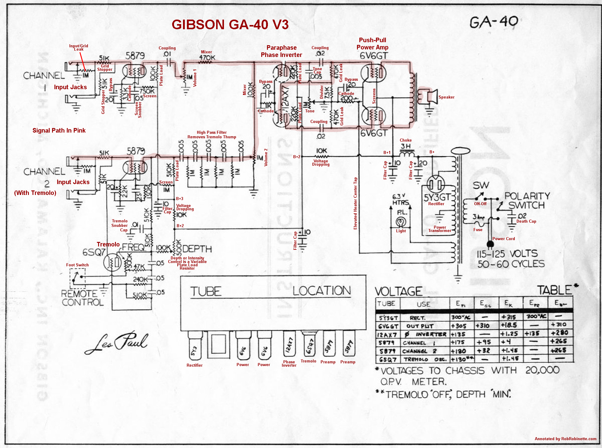
The GA-40 V3 uses one 5879 pentode per channel as a single preamp stage. The paraphase phase inverter lower triode gets its signal to its grid through the upper 470k grid leak resistor. The tremolo oscillation is fed to the channel 2 preamp plate. The "Tremolo High Pass Filter" is a fifth order high pass filter which removes tremolo thumping that can be created in the tremolo oscillation. Each RC network stage rolls off at a slope of 6dB per octave at 32Hz. Five successive filters create a very steep filter cut which allows the corner frequency to be set low enough to allow normal bass response in the tremolo channel (Channel 2) while still killing tremolo thump.
1957 Magnatone 280 With Stereo Harmonic Pitch-Shift Tremolo
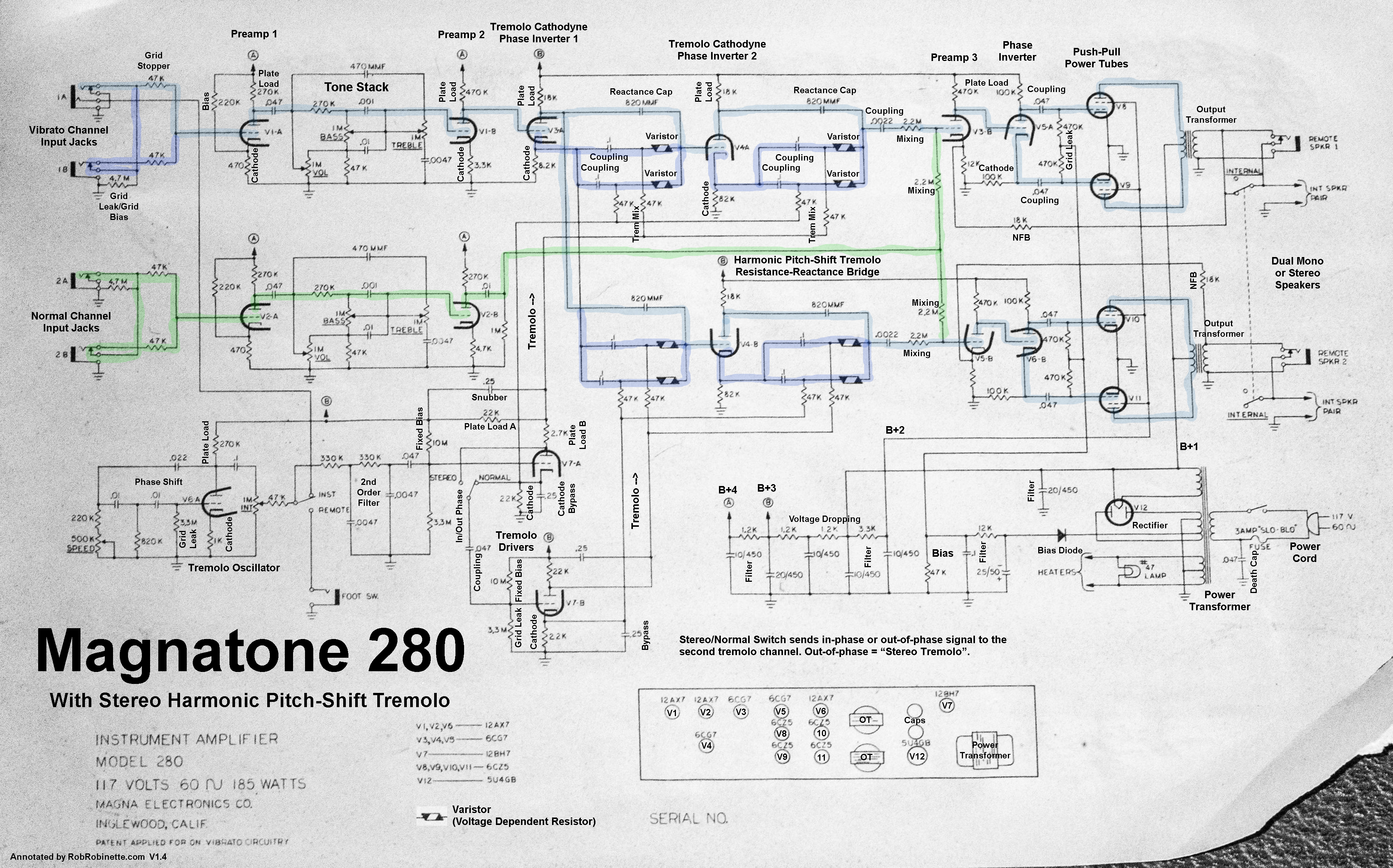
This amplifier won the Tremolo War with by far the most complex and intricate tremolo design. Each stereo channel has its own tremolo driver, harmonic pitch-shift circuit, power amp and speaker. Vibrato Channel signal path shown in blue. Normal Channel signal path shown in green. Tremolo Oscillator and Tremolo Drivers at lower left. Dual channel Harmonic Pitch-Shift circuits at upper center. Click image to see full size schematic.
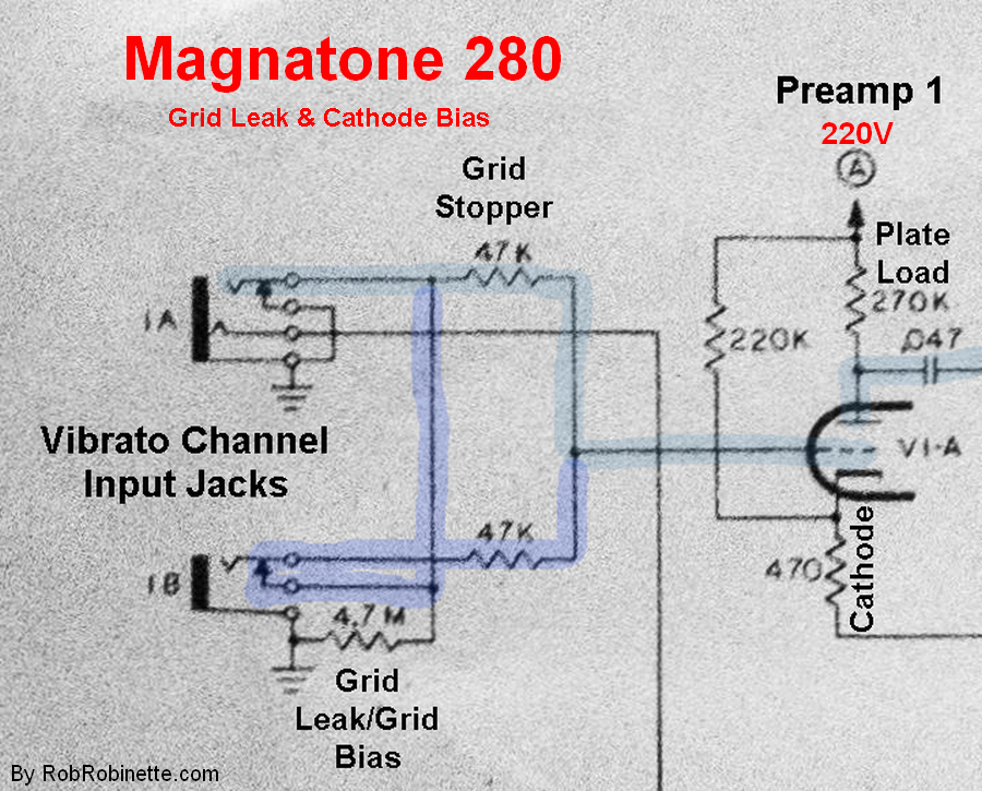
Magnatone used an unusual first stage bias circuit in some of their amps including the 280. Using the upper 1A "High" input jack bias voltage is generated by the 4.7M Grid Leak/ Grid Bias resistor because it creates a voltage drop as grid current flows through it. The 470 ohm Cathode resistor generates a voltage drop when electrons flow from the cathode to plate. Since this circuit has no blocking capacitor the grid bias voltage will be passed to the guitar. When the lower 1B "Low" input jack is used the 4.7M grid leak resistor is bypassed so no grid leak bias is generated.
Rock and Roll Globe Article About Scott Totten's Magnatone 280 Rebuild
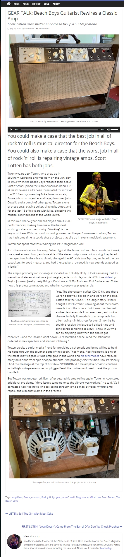
How Humbucking Guitar Pickups Work
Humbucking pickups are really two single coil pickups connected together in a way that cancels noise and doubles the pickup output voltage. Humbuckers use common mode noise rejection to reduce hum and other electromagnetic noise picked up from surrounding sources like fluorescent lights. Any noise that gets into both pickup coils is nullified when the two signals from the two coils are combined because the noise signals from the two coils are of opposite phase.
In other words the positive noise signal is added to the negative noise signal and they wipe each other out. We get a "positive" coil and "negative" coil by simply winding the wire in the opposite direction.
Why doesn't the guitar string signal get nullified like the noise? Because of the opposite magnetic polarity of the pickups' pole pieces. One pickup has North up magnets and the other has South up magnets. This flips the signal polarity of one coil so the string signals are in phase, not out of phase like the noise. The string signals from the two coils are added together instead of being subtracted and nullified.
Just like two humbucker pickup coils, two separate pickups can be paired together to work as humbuckers and reduce noise if the two pickup coils are connected the right way.
You need two things to get hum cancelation in a humbucker pickup or between two single coil pickups: Opposite electrical current flow in the two coils--one coil's string generated current flows clockwise, the other coil flows counter-clockwise. The two pickups must also have opposite magnetic polarity (North+South).
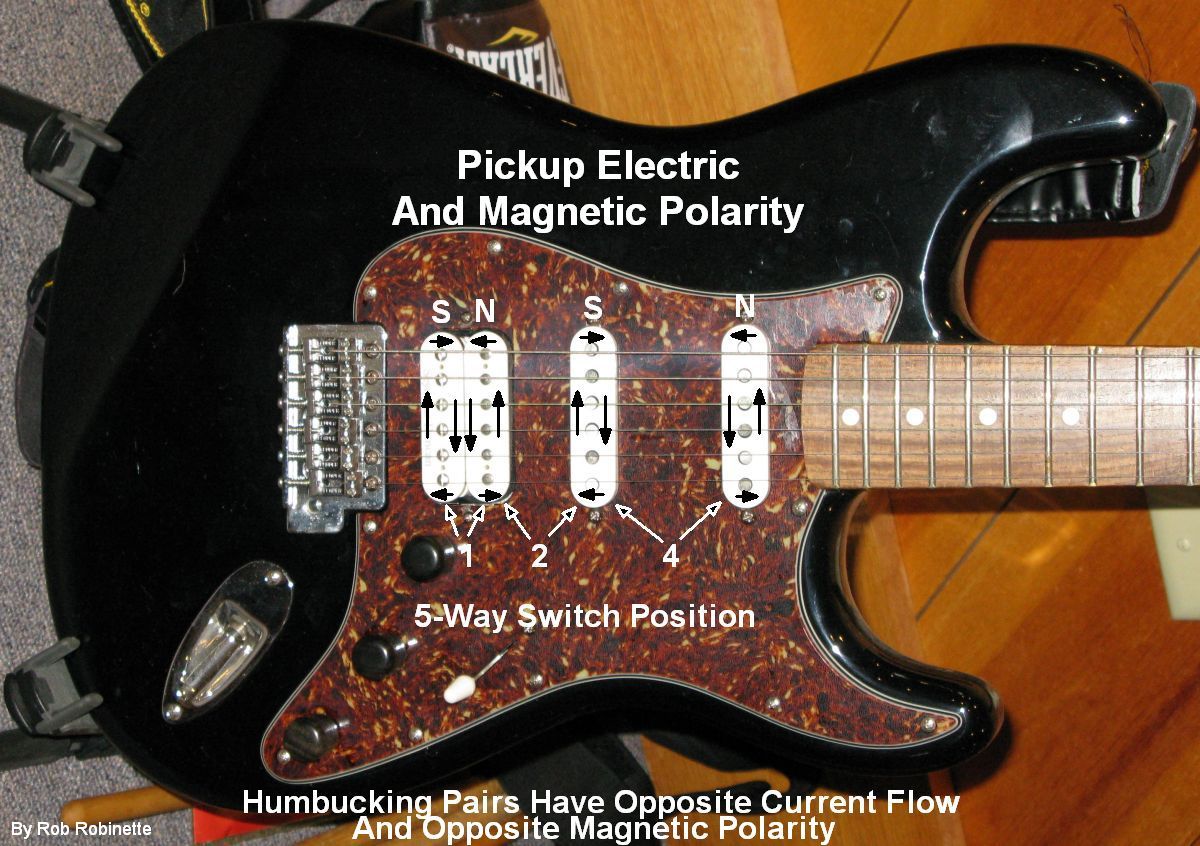
The two coils of the bridge humbucker circulate electric current generated by the strings in opposite directions. The black arrows show the direction of current flow around the pickup coils. The same is true when you select switch position 2 which pairs the right bridge humbucker coil with the mid pickup and switch position 4 which pairs the mid and neck pickups. The magnetic poles of the left humbucker coil are South up and the right coil is North up. In switch position 2 the North bridge coil is paired with the South mid pickup. In switch position 4 the South mid pickup is paired with the North neck pickup. 5-Way switch positions are: 1 Bridge Humbucker, 2 North Humbucker coil + South Mid Pickup, 3 Mid Pickup, 4 South Mid Pickup + North Neck Pickup, 5 Neck Pickup.
It is pretty obvious when you pair two coils out of electrical phase (both coils' electrical flow running in the same direction)--the guitar tone is weak and tinny because the two string signals are subtracting and nullifying each other. The solution is easy, just swap one of the coil's two hookup wires to reverse its electrical flow.
It's much harder to detect by ear when a pair of coils are in phase electrically but out of phase magnetically--they will sound normal when paired but there will be no hum cancelation so you may notice some 60Hz electrical hum. The easiest way to check the magnetic polarity of two pickups is to carefully move the two pickups close together--top pole to top pole. If they magnetically repel each other they are the same polarity and will not hum cancel. If they attract each other they are opposite polarity and will hum cancel when paired. You can also purchase a $9 Schatten Design Magnetic Polarity Tester from Stewmac which makes checking installed pickups a breeze.
Many pickup manufacturers will change the magnetic polarity of their pickups for no charge. I had to do this on my Telecaster to get the mid and neck pickups to hum cancel. Note that if you change the magnetic polarity of a pickup the current flow direction will also reverse so you will have to swap its hookup wires to keep the same electrical polarity. Be aware that some aftermarket pickups have the opposite magnetic polarity as modern Fender pickups so when purchasing pickups that will be paired for humbucking make sure you know what magnetic polarity you're ordering.
Normal Humbucker Magnetic Polarity
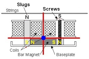
Note the magnet on the bottom in contact with the Screw and Slug poles. Note how the bar magnet, slugs and screws all have a North and South pole.
Transistor Equivalent Circuits
![]()
NPN transistor on the left, PNP on the right. A positive Base voltage on an NPN transistor will allow current to flow through the resistor. A negative Base voltage on a PNP transistor will allow current to flow.
Here's two transistor circuits that look and function very much like tube amp circuits. The first is the transistor common emitter amplifier:
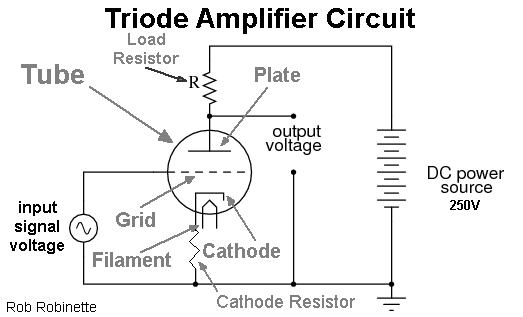
![]()
Tube triode amp circuit on the left, transistor common emitter amp on the right. Remove transistor resistor R2 and this circuit looks just like a tube amplifier stage. The two circuits serve the exact same purpose.
The big difference between the tube and transistor amp circuit is the addition of resistor R2. Resistors R1 and R2 form a voltage divider which sets the bias voltage on the transistor's base (similar to a tube's control grid). Resistors RC and RE determine the amplifier gain and set the max current. Capacitor CE is a standard bypass cap to boost gain. Capacitors C1 and C2 are standard coupling caps.
Here's the transistor emitter follower. It bears an uncanny resemblance to a tube cathode follower:
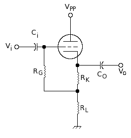
![]()
Triode tube cathode follower on the left, transistor emitter follower on the right. Remove transistor resistor R1 and this circuit looks just like a tube cathode follower. The two circuits serve the exact same purpose.
Again, the big difference between the tube and transistor amp circuit is the addition of resistor R1. Resistors R1 and R2 form a voltage divider which sets the transistor's bias voltage on the base (input). A transistor emitter follower can be used as an easy to implement tone stack buffer or effects loop buffer because they do not need a cathode heater.
How Voltage Dividers and Pots (potentiometers) Work
When I first got into electronics I had a hard time understanding voltage dividers but they are really pretty simple. Understanding them is important because a tube amp is full of them. Even tone controls and tone stacks can be thought of as voltage dividers. The Soldano SLO-100 high gain amp uses five voltage dividers to bleed off excess guitar signal to prevent harsh over-overdrive.
Classic Voltage Divider
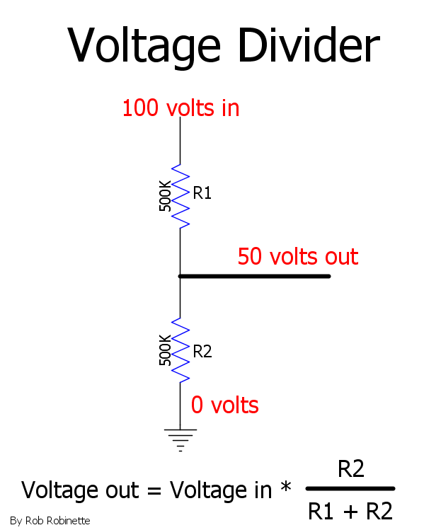
Note how there is 100 volts at the top of the resistors and 0 volts at the bottom (ground). The resistance above the output is R1 and the lower is R2.
A voltage divider literally divides voltage. Take a look at the diagram above. We have two 500k resistors with 100 volts at the top and 0 volts (ground) at the bottom. If we tap the resistors at the top we get 100 volts, tap the resistors at the bottom and we get 0 volts. Now if we tap the resistors at the middle, half way down at 500k, we will get half the voltage, 50 volts. Tap higher and the voltage moves toward 100v, tap lower and the voltage goes down toward 0 volts.
Note the equation at the bottom of the diagram above: The formula to calculate the voltage out of a voltage divider is:
Voltage Out = Voltage In * resistance below the output / total resistance
We can calculate the voltage out of the voltage divider by multiplying the Voltage in * R2 / (R1 + R2).
For our voltage above we get: 100v * 500,000 / (500,000 + 500,000) = 100v * .5 = 50 volts out.
The R2 / (R1 + R2) determines the ratio of the upper to lower resistance. If you make the lower resistor smaller, more voltage will be bled to ground so you will have less voltage out.
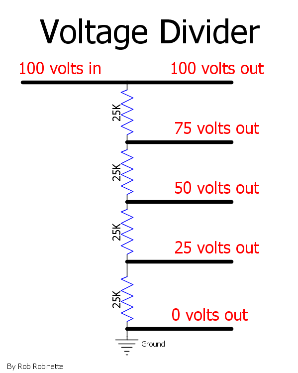
We have 100 volts at the top of this multi-resistor divider and 0 volts (ground) at the bottom. We get lower voltages as we move down the resistance.
If we make the top resistor in a two resistor divider 250k and the lower resistor 750k we know less voltage would be bled to ground so the output voltage would be higher: 100v * 750,000 / (250,000 + 750,000) = 100v * .75 = 75 volts out.
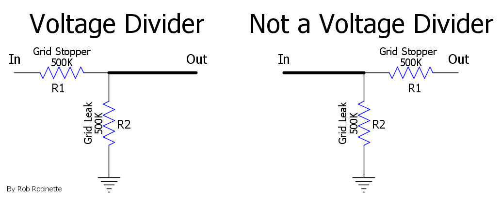
Note how the placement of the upper resistor is important. The circuit on the right is not a voltage divider.
Treble Peakers
Treble Peakers are a special type of bright cap that bypass the upper (attenuating) resistor in a voltage divider. By bypassing the upper resistor high frequencies bypass the voltage divider and are not cut. A Treble Peaker cap acts as a semi-active high frequency boost. In the voltage divider below the guitar signal is cut in half except for high frequencies--they go around the divider and are not cut so in effect high frequencies above the bright cap corner frequency are doubled in volume compared to the rest of the guitar signal. Treble Peakers are used in all high gain tube guitar amplifiers to give the amp high gain sizzle. The Marshall JCM800 uses two 470pF Treble Peakers and the Soldano SLO-100 uses a single .002uF Treble Peaker in the Overdrive Channel and a tiny 120pF in the Clean Channel. A common mod in these amps is to remove a Treble Peaker to cut ice pick highs.
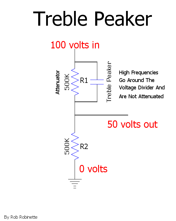
The Treble Peaker cap allows high frequencies to go around the upper resistor so they are not cut by the voltage divider.
Here's an online Grid Stopper Calculator to calculate the frequency cutoff of a Treble Peaker.
Potentiometers (pots)
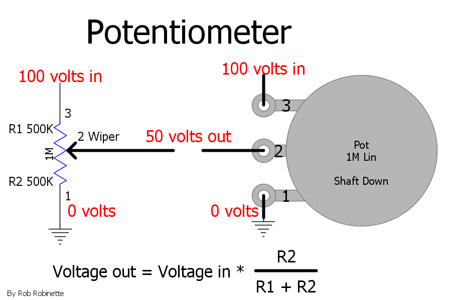
A potentiometer (pot) is simply a variable voltage divider. Schematic symbol on the left, layout symbol on the right. Pot terminal numbers "1, 2, 3" are shown on both symbols. The potentiometer got it's name from voltage potential. "Shaft Down" means the pot's knob shaft is pointing away from you.
Now take a look at the pot diagram above. Look familiar? A pot is simply a variable voltage divider. If we turn the voltage tap, or wiper, to the top of the pot we get 100 volts, turn the wiper to the bottom and we get 0 volts (because it's directly connected to ground). In the diagram the wiper is at 50% so there's 500k above the wiper and 500k below the wiper so the input voltage is cut in half. Now we can tap the voltage by placing the wiper anywhere between the 100 volts at the input, to the 0 volts at the ground connection.
The formula to calculate the voltage out is the same as a voltage divider: resistance below the wiper / total resistance. "R1" is the pot resistance above the wiper and "R2" is the resistance below the wiper on the ground side. For example we turn the 1M linear pot 1/4 turn up from "off" we know that 1/4 of 1M = 250k. That 250k is movement up from off or 0 volts so R2 = 250k and R1 would be the rest of 1M or 750k. Voltage out = 100v * 250,000 / (250,000 + 750,000) = 100v * .25 = 25 volts out.
Pot With Arrow
![]()
The downward arrow pointing to "CW" means the direction the wiper moves when you turn the pot knob clockwise or "up." If "CW" is not shown then assume the arrow points in the clockwise direction. If there is no arrow you can assume that the wiper moves upward when you turn the pot clockwise.
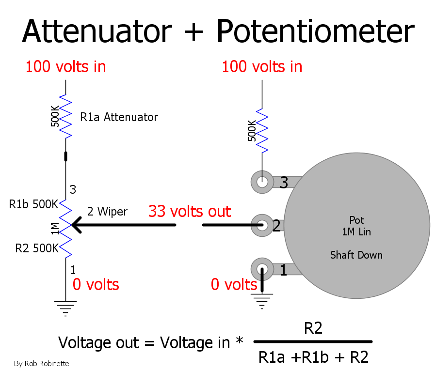
Attenuator resistor (R1a 500k) added to a volume pot to reduce max volume. The R1a resistance is added to the pot's "above the wiper" resistance so it adds attenuation (cuts the max guitar signal out). With the pot set to the mid point with 500k + 500k above the wiper and 500k below the wiper gives us a 66% cut in the guitar signal compared to a 50% cut without the attenuation resistor. With the pot set to max the attenuator resistor will still cause a 33% cut in guitar signal. This simple circuit can be used in high gain preamp circuits to control excess gain. If needed, a bright cap can be placed in parallel with the attenuator resistor to allow high frequencies to go around the resistor and keep the attenuator resistor from darkening the amp's tone. The formula to calculate the voltage out is the same as a voltage divider: resistance below the wiper / total resistance.
Capacitive Voltage Dividers
Resistance based voltage dividers work the same with AC or DC voltage but we can put two capacitors in the same configuration as the R1 and R2 resistors above and form a capacitive voltage divider that divides AC voltage. The capacitors block DC voltage and current so only AC voltage is divided.
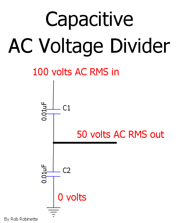
Electronics Tips
Rob Hull's Easy to Use Resistor Color Code Reader
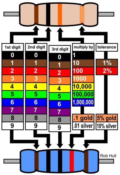
Note the 3-band resistor on top and 4-band on the bottom.
Common amp electronic component symbols. This is pretty much all you need to know to read tube amp schematics.
Calculating Parallel Resistance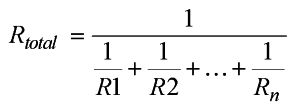
The first time I saw the equation for calculating the resistance of resistors in parallel I had a mental meltdown. It actually stopped me in my tracks as I attempted to self-learn electronics back in high school. Then I discovered the calculator's 1/x or inverse key that made this equation super simple.
Let's say you have three resistors in parallel: R1 is 100 ohms, R2 is 200 ohms and R3 is 300 ohms.
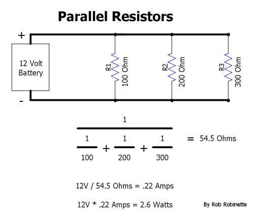
Circuit total resistance = 54.5 ohms. Using Ohm's Law current = .22 amps, power = 2.6 watts.
This would be the key sequence on the calculator
100 1/x + 200 1/x + 300 1/x = 1/x
Don't forget that last 1/x key, it's for the 1/ on top of the equation. 54.5 ohms should be showing on the calculator screen when you hit that last 1/x key. Give it a try right now, open your computer's on screen calculator and follow the key sequence.
The Windows built-in calculator has a 1/x key. If the 1/x key is not showing when you open the Windows calculator select "Scientific" then click on the ↑ (Up Arrow) key and you will see the 1/x key.
Measuring Resistance In Circuit
I have seen many amps "repaired" with new resistors because the owner/builder measured resistors' resistance and replaced them due to what they thought was component value drift.
Your multi-meter applies a very low level DC voltage and current to a resistor in order to measure its resistance. The problem is when you try to measure resistance with the resistor in an amp or "in circuit" there is often a "back door" path for your meter's current flow that will cause an inaccurate resistance measurement.
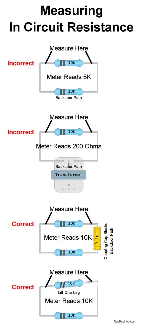
The first two circuits have two paths for the meter's test current so measured resistance is much less than expected. In the third circuit a cap blocks current flow so an accurate reading is taken. "Lifting a leg" in the last circuit also ensures an accurate measurement.
The key to knowing when an in circuit measurement will be true is being able to read the schematic so you can follow the "back door" path(s) to see if it will cause inaccuracy. An unpowered tube grid, plate and cathode are "dead ends" that will not pass current. Capacitors are also dead ends that will not allow DC current to flow. Typical transformer windings have from 0.5 to 300 ohms of resistance so they do provide a back door. To be sure you can always unsolder one end of a resistor to get an accurate measurement.
Ohm's Law Pie Chart
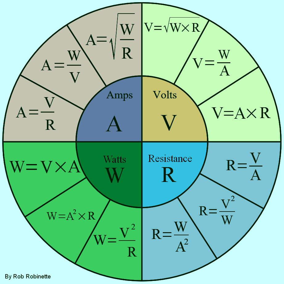
It may be easier for you to remember this stuff using A, V, R and W for Amps, Volts, Resistance and Watts in these equations. For example the lower left Watts section shows three ways to calculate power: Volts * Amps or Amps squared * Resistance or Volts squared / Resistance.
Ohm's Law "Rules of Thumb"

Memorize "VAR" for Volts Amps Resistance and you can remember Ohm's
equations. Place your thumb over what you want to know and the equation is
shown. Example 1: You want to know volts, place your thumb over V and "A R" is
left so Amps*Resistance=Volts. Example 2: You want to know amps, place your
thumb over "A" and and "V over R" is showing so Volts/Resistance=Amps
Ohm's Law Spreadsheet
Simply enter two values of volts, amps, ohms and watts. If three or four values are entered some of the calculations will be incorrect. Download the Ohm's Law Excel Spreadsheet or the Libreoffice version. To format spreadsheet cells for engineering notation use this format code: ##0.000E+##
Your Calculator's Engineering Notation Mode
The "Engineering Mode" available in Excel spreadsheets, scientific calculators (including the Windows built-in scientific calculator) and mathematic software is made to make keeping track of micro, nano, pico, kilo and mega much easier during calculations. Engineering Mode is like scientific mode, which uses exponents for very large and very small numbers, but the exponent is always a multiple of three which fits this chart nicely:
|
Prefix |
Name |
Value |
Calculator |
|
M |
mega |
10^6 |
E6 |
|
k |
kilo |
10^3 |
E3 |
|
m |
milli |
10^-3 |
E-3 |
|
u |
micro |
10^-6 |
E-6 |
|
n |
nano |
10^-9 |
E-9 |
|
p |
pico |
10^-12 |
E-12 |
Notice how all the exponents are multiples of 3? The exponent tells you how many places to shift the decimal point. A negative exponent means we shift the decimal point to to the left to make the number smaller. A positive exponent means we shift to the right for a larger number. With 47E-6 we would shift the decimal point 6 places left to give you .000047
250pF would be shown in the calculator as "250E-12" (see chart, read E-12 as pico)
32 milliamps would be shown as "32E-3"
56K would be "56E3" and 1M would be "1E6"
Suppose you want to determine the cutoff frequency of a high pass filter and need to multiply 1M resistance by 250pF.
Instead of entering "1,000,000 * .000,000,000,250 for 1M and 250 pico Farads you would simply enter 1 EEX 6 x 2 5 0 EEX 1 2 +/- =
The EEX key is the "enter exponent" key and the +/- key is the "change sign" key to make the exponent negative. The calculator will show "250E-6" so read the "E-6" as micro.
When you multiply 1E6 * 250E-12 the calculator will show the answer as 250E-6. We know E-6 means micro so the answer is 250uF.
.1uF = 100nF so it would be shown in the calculator as "100E-9" and 470pF as "470E-12"
On HP calculators press the Mode button to select the Engineering Mode.
To format Excel spreadsheet cells to use engineering notation use this format code: ##0.000E+00
Have comments or corrections? Email rob at:
![]()
By Rob Robinette
Suggested follow on reading:
How Tubes Work How electrons flow through a vacuum tube.
How to Read Tube Amp Schematics It's easier than you think.
How the Fender 5E3 Deluxe tube amplifier works
Deluxe Models from the Woodie to the 68 Custom Deluxe Reverb.
Fender 5F6A Bassman Information and Modifications
How the Fender blackface AB763 Deluxe Reverb Works
AB763 Model Differences What's the difference between a blackface Vibroverb, Vibrolux and Super Reverb?
How the TMB Tone Stack Works It looks like a simple tone circuit but it's not.
How Fender Input Jacks Work Bright, Normal, High, Low: it's an elegant circuit.
By Rob Robinette
References
RCA Corporation, RCA Receiving Tube Manual, RC30.
Merlin Blencowe, Designing Tube Preamps for Guitar and Bass, 2nd Edition. This is my personal favorite tube amp book.
Merlin Blencowe, Designing High-Fidelity Tube Preamps
Morgan Jones, Valve Amplifiers, 4th Edition.
Richard Kuehnel, Circuit Analysis of a Legendary Tube Amplifier: The Fender Bassman 5F6-A, 3rd Edition.
Richard Kuehnel, Vacuum Tube Circuit Design: Guitar Amplifier Preamps, 2nd Edition.
Richard Kuehnel, Vacuum Tube Circuit Design: Guitar Amplifier Power Amps
Robert C. Megantz, Design and Construction of Tube Guitar Amplifiers
Neumann & Irving, Guitar Amplifier Overdrive, A Visual Tour It's fairly technical but it's the only book written specifically about guitar amplifier overdrive. It includes many graphs to help make the material easier to understand.
T.E. Rutt, Vacuum Tube Triode Nonlinearity as Part of The Electric Guitar Sound
[ Reading Amp Schematics ] [ Draw Tube Load Lines ] [ TMB Tone Stack ] [ Death Cap ] [ Widowmakers ] [ How the 5E3 Deluxe Works ] [ Deluxe Models ] [ DRRI & 68 CDR Mods ] [ My 5E3 Build ] [ The Trainwreck Pages ] [ Fender Input Jacks ] [ B9A Prototype Boards ]