Reverb & Tremolo
By Rob Robinette
Have comments or corrections? Email rob at: robinette at comcast dot net
Add-A-Circuit Reverb & Tremolo Based on the 1965 Fender AA1164 Black Face Princeton Reverb
Compact Reverb and Tremolo Using Two ValveWizard B9A Development Boards
Solid State Spring Reverb from the Fender Hot Rod Deluxe
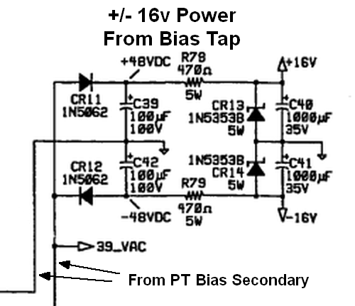
Power Solid State Devices from your amp's power transformer bias tap
Bias Tremolo Add-On Circuit for Small Fixed Bias Power Tubes
Tube Tremolo for Cathode Biased Amps
Tube Tremolo Add-On Circuit for Large Power Tubes
WARNING: A tube amplifier chassis contains lethal high voltage even when unplugged--sometimes over 700 volts AC and 500 volts DC. If you have not been trained to work with high voltage then have an amp technician service your amp. Never touch the amplifier chassis with one hand while probing with the other hand because a lethal shock can run between your arms through your heart. Use just one hand when working on a powered amp. See more tube amplifier safety info here.
The easy way to add reverb and tremolo is with this, my favorite pedal of all time, the Strymon Flint. It does everything from adding a little warmth and thickness to full up 60's surf. The "Color" control is a very usable tone knob. The '61 harmonic tremolo setting is a really nice bonus. Try this surf setting and you'll have a blast:
Surf City
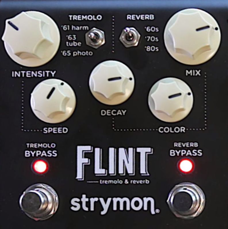
This Strymon Flint + 5E3 = surf heaven. Use the above knob and switch settings for a wonderfully authentic surf tone. Switches are set for '63 tube tremolo and '60's reverb. Here's an excellent youtube demo by 60Hz Hum.
The Hard Way to Add Reverb
I tried to design the simplest 2-tube reverb & Tube Tremolo layout possible. I used the proven circuit from the AA1164 Fender Blackface Princeton Reverb and offer up layout diagrams for a simple reverb and a tremolo to add to an amp design. The reverb circuit uses one triode of a 12AX7 (half the tube) and one whole 12AT7 tube. The tremolo circuit uses one triode of a 12AX7. See how spring reverb works here.
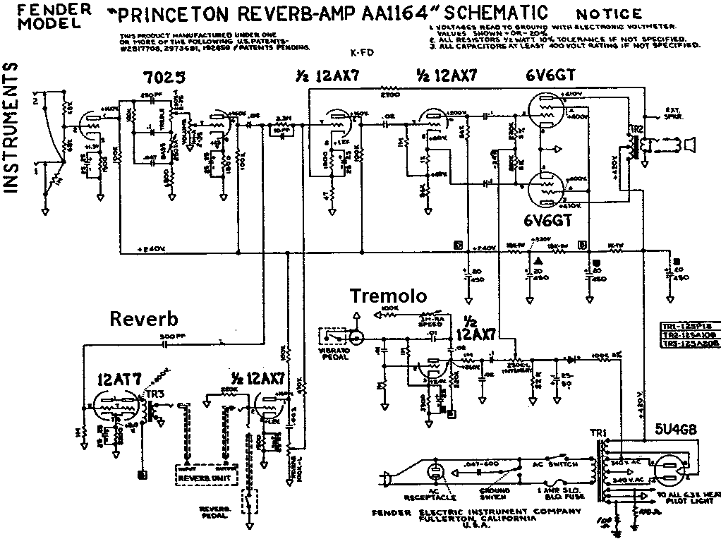
Princeton Reverb reverb circuit at lower left.
Compact 2-Tube Reverb Add-On Circuit
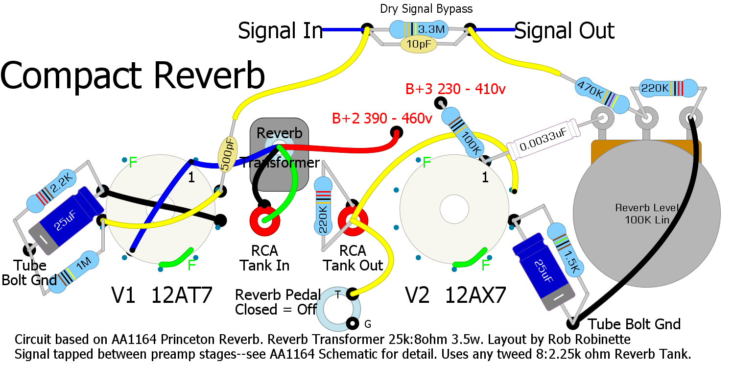
Here's the Compact Reverb layout pdf and DIYLC file (DIY Layout Creator) for the reverb add-on circuit. Use the 470K resistor on the Reverb Level pot to adjust your reverb signal. One person that built this circuit needed to delete it to get the wet signal level up.
The host amplifier will need to supply between 390 to 460v DC for the reverb transformer and 230to 410v for the tubes and about 1 amp of filament heater current.
Adding this reverb circuit to an amplifier will change its tone. The big 3.3 meg reverb mix resistor increases the load impedance on the upstream circuit and increases the input impedance of the downstream circuit.
This circuit really needs three preamp gain stages with the 3.3M reverb mix resistor signal tap placed between gain stage 2 and 3, just like in the Princeton Reverb and AB763 amps. See the AA1164 schematic above to see how it was done in the Princeton Reverb. For the 5E3 I recommend tapping the circuit between the Normal channel volume pot pin 3 (output) and V2A pin 2 (grid).
Compact Reverb Add-On Circuit Schematic
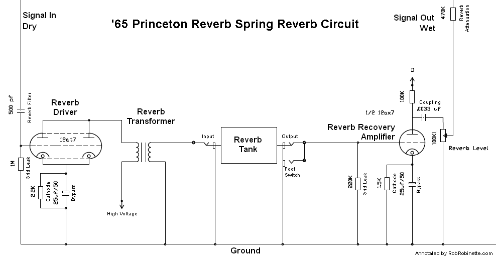
Note that all of the signal flows through the reverb tank so this circuit's output is 100% wet. The dry signal bypasses this circuit through the 'tap circuit' made up of the paralleled 3.3M resistor and 10pF bypass cap shown at the top of the layout diagram.
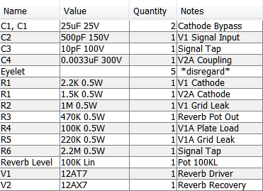
Compact Reverb Add-On Bill of Materials
You also need a 220k Reverb Attenuator resistor which is placed on the Reverb Level pot.
Compact Reverb and Tremolo Using Two ValveWizard B9A Development Boards
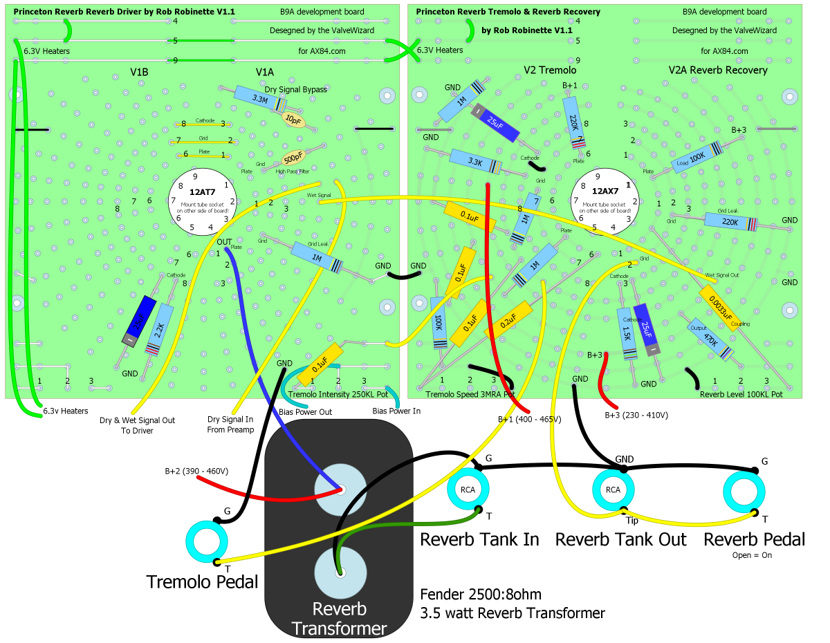
V1A and V1B (left board) are used for the Reverb Driver. V2A is the Reverb Recovery amp and V2B is used for Tremolo (see circuit below).
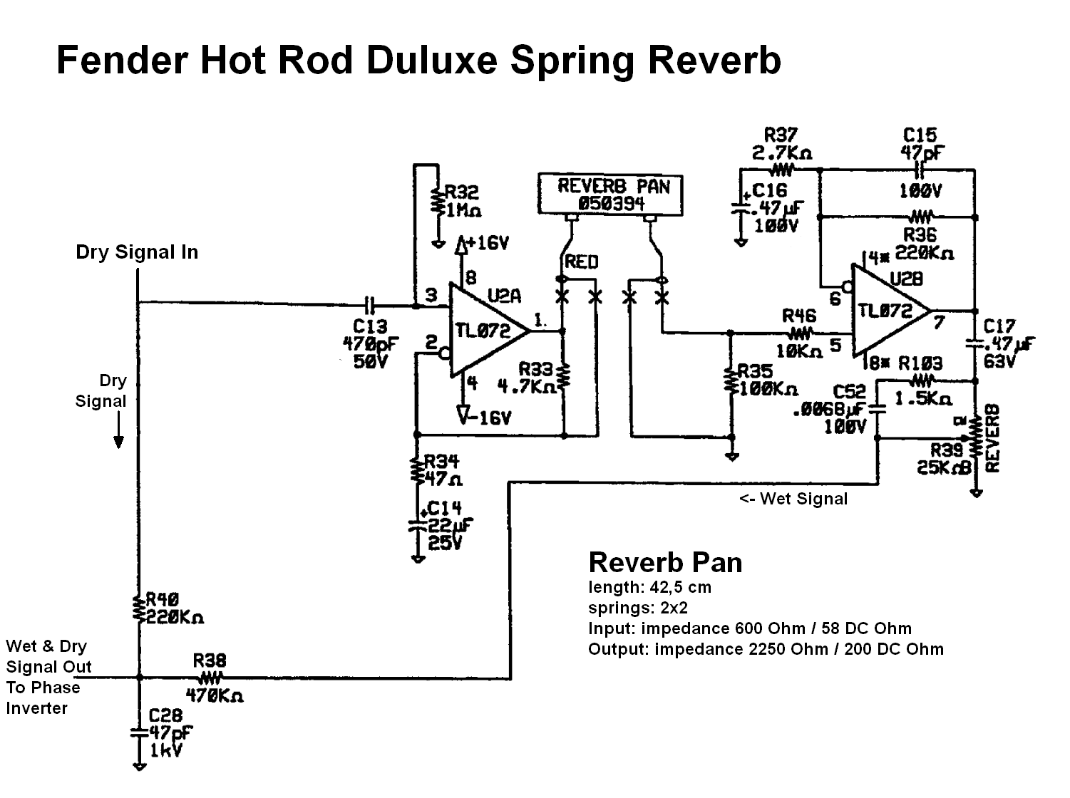
Solid State Spring Reverb
This simple, inexpensive spring tank reverb circuit is taken from the Fender Hot Rod Deluxe. It uses a single, less than one dollar TL072CP op amp as the reverb driver and reverb recovery amps. The reverb circuit is inserted just before a guitar amplifier's phase inverter in a push-pull amp or just before the driver (last gain stage before the power tube) in a single ended amp.
If your power transformer doesn't have a 40v bias tap you can use this Hammond 187D36 36 volt transformer instead and connect its second power lead to the Power Supply Board's ground bus shown at bottom left "40V AC transformer lead." The power circuit will work with an input voltage between 30 tp 60 volts AC RMS and still put out +/-16 volts DC.
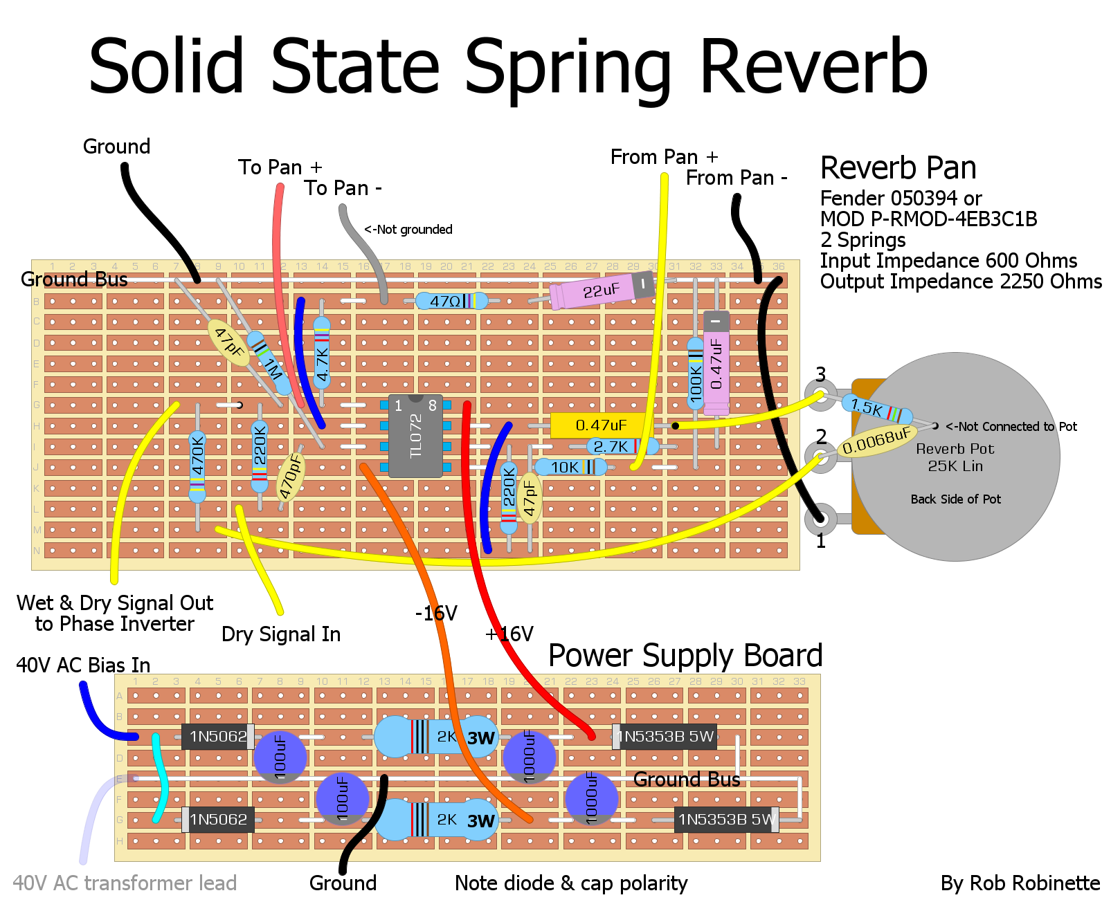
The reverb pan's input must not be grounded. The "To Pan -" connection is not a ground so the pan's input connector must be insulated from the pan. The reverb pans listed below have insulated inputs. The circuit is built on 3.7" x 1.5" and 3.4" x 1" tripad boards. I recommend you use an 8-pin dip socket (not shown above) so you don't destroy the chip trying to solder it directly to the board. If you use a separate 36v transformer you should attach its second power lead to the Power Supply Board's ground bus--shown in ghosted blue above.
Derive +/- 16v Power For TL072 From PT Bias Secondary
Texas Instruments recommends 5 to 15v and -5 to -15 power input with +/- 18v max at pins 4 and 8, the Hot Rod Deluxe specs 16v. The Hot Rod Deluxe has lots of solid state components to power so I bumped up the value of the two resistors, R78 and R79 to 2K 3Watt to reduce the circuit's current demand since we're only powering a single TL072.
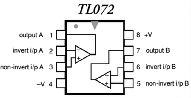
The Ti TL072 is simply two op amps packaged in a dip. The TL072CP is a low noise version of the TL072 and costs about 1$.
Bill of Materials
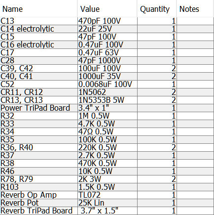
A Fender 050394, Accutronics 4EB3C1B or MOD P-RMOD-4EB3C1B reverb pan and 8 pin dip socket are also needed.
I recommend the $19 MOD P-RMOD-4EB3C1B Pan Specs: Long (16 ¾") 2 Spring Unit, Long Decay, Input Impedance 600 Ohms, Output Impedance 2250 Ohms, Mounting: Horizontal Open Side Down, Connectors: Input Insulated/Output Grounded.
Power Solid State Devices from Bias Tap
This is the standalone power supply used above. It takes power from the power transformer's 40v AC bias tap and converts it to +16v and -16v to power solid state devices (transistors and chips) in your tube amplifier. The power circuit will work with an input voltage between 30 to 60 volts AC RMS and still put out +/-16 volts DC.
If your power transformer doesn't have a 40v bias tap you can use this $13 Hammond 187D36 36 volt transformer instead and connect its second power lead to the Power Supply Board's ground bus shown at bottom left "40V AC transformer lead."
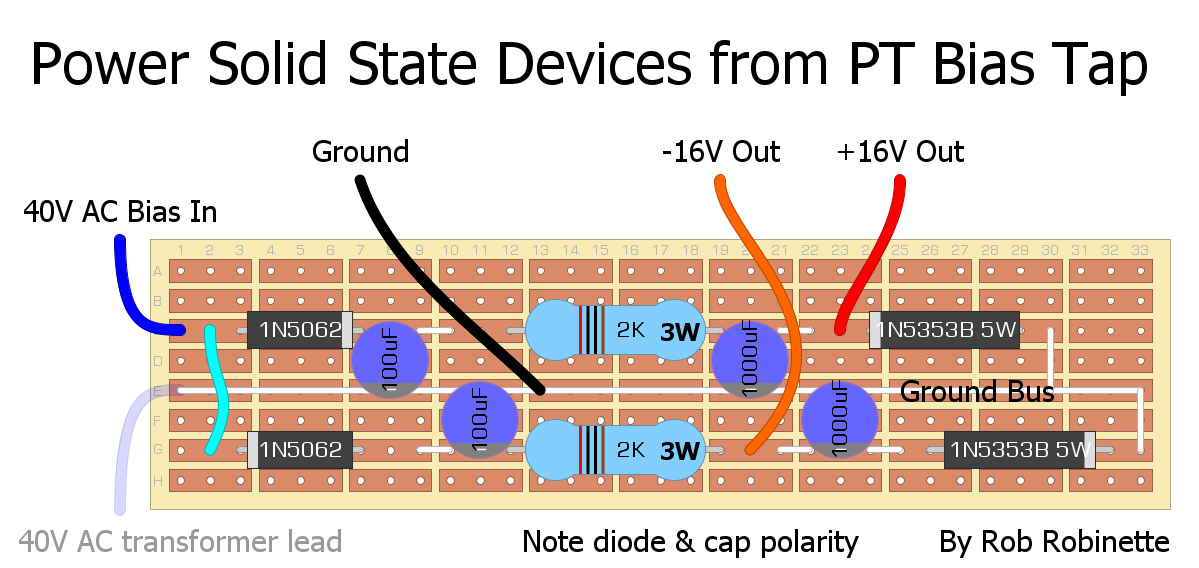
If you use a separate 36v transformer you should attach its second power lead to the Power Supply Board's ground bus--shown in ghosted blue above at bottom left.
Derive +/- 16v Power For Chips & Transistors From PT Bias Secondary
Power Supply Bill of Materials
Tube Tremolo Add-On Circuits
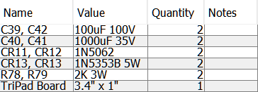
Bias Tremolo Add-On Circuit for Small Fixed Bias Power Tubes
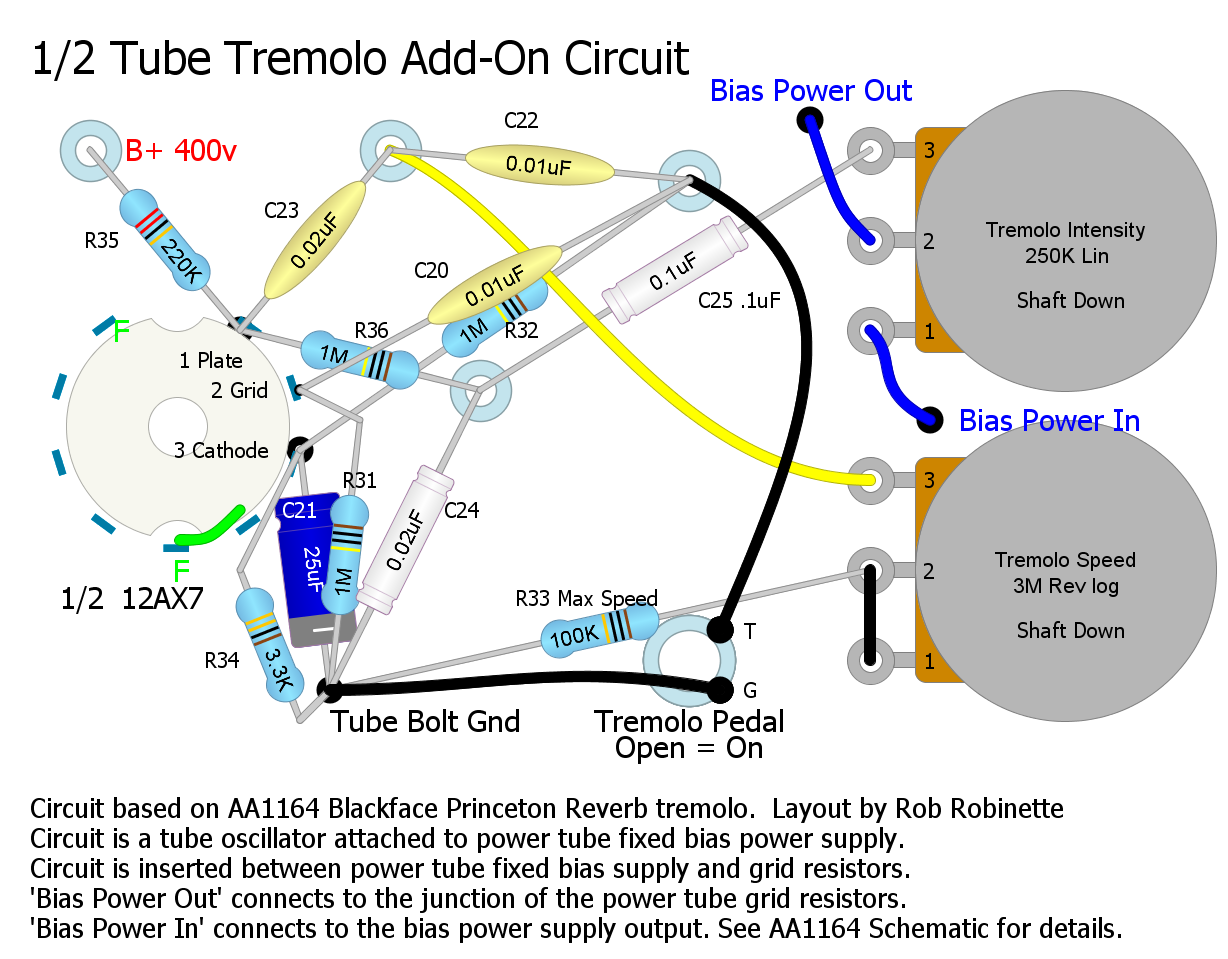
This circuit is also based on the 1965 AA1164 Blackface Princeton Reverb and is best used for small power tubes like the 6V6 and EL84 using fixed bias. Amplifiers using cathode bias or 6L6 and larger power tubes typically modulate the signal instead of the bias for tremolo. The circuit operates by wavering the power tube bias voltage which alters the volume of their output. Download the DIYLC layout file here.
The Intensity control (right in schematic above) shifts the balance between Bias Power Output and the modulated tremolo voltage. The Speed control (upper center) alters the resistance in the first RC pair (C23 and 3MRA Pot + 100K R33) which changes C23's charge time which changes the tremolo circuits oscillation frequency (more resistance = slower charging = slower tremolo). The Tremolo Pedal control shunts (shorts) the oscillation signal to ground when closed so if no tremolo pedal is plugged in the tremolo is on.
You can increase the maximum tremolo intensity by reducing the size of the 1M R36 resistor to 500k or 220k.
Small Power Tube Tremolo Add-On Bill of Materials
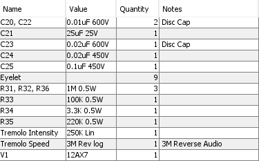
Tube Tremolo for Cathode Biased Amps
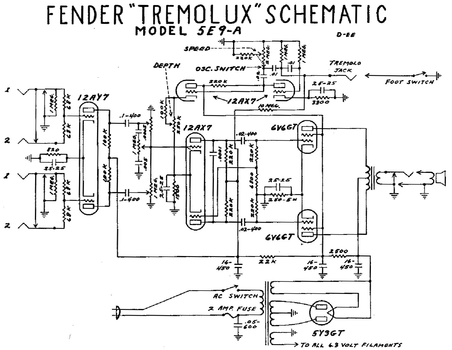
The 5E9A Tremolux applies the tremolo signal to the phase inverter cathode so it can be used in pretty much any amp: fixed bias, cathode bias and small or large power tube amps.
Tube Tremolo Add-On Circuit for Large Power Tubes
AB763 Signal Tremolo Circuit
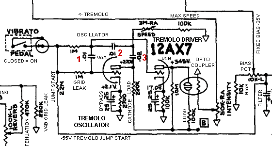
Tremolo circuit from the Fender AB763 Deluxe Reverb. Tremolo is applied to the guitar signal at the phase inverter input instead of the power tube bias like the preceding small power tube tremolo circuit. V5A is the oscillator on the left and V5B is the tremolo driver on the right.
The AB763 tremolo circuit acts as an automatic wavering volume control and acts directly on the guitar audio signal. The guitar signal is tapped just before the 220k channel mixing resistor and phase inverter. The tremolo circuit bleeds the guitar audio signal to ground by a light dependant resistor (LDR) in the opto-isolator (or opto-coupler, often called the 'roach' because it looks like a bug). The opto-isolator is made up of a neon light bulb and a light dependant resistor. [We could call the neon bulb V10 because it is a single electrode tube ;) ] When the neon bulb is dim the LDR is at high resistance and less guitar signal is bled to ground. When the neon bulb is bright the LDR resistance is low and more signal is bled to ground.
The triode on the left is the Oscillator and its grid is connected to its plate through three oscillator caps that cause the plate voltage to oscillate. It's oscillation flows to the grid of the triode on the right, the Tremolo Driver. The Tremolo Driver amplifies the oscillation to drive the neon light bulb. The oscillating current from the driver tube plate runs through the neon light bulb causing it to oscillate in brightness from bright to dim. As the brightness of the neon bulb changes the output volume of the amp changes with it.
The Intensity control (lower right in schematic above) alters the amount of the guitar signal that is sent to the light dependant resistor (more signal sent to the LDR = more intense tremolo). The Speed control (upper center) alters the resistance in the first RC (resistor capacitor) pair which changes the RC's capacitor charge time which changes the tremolo circuits oscillation frequency (more resistance = slower charging = slower tremolo). The Tremolo Pedal control provides the ground needed for the oscillator to operate so if no tremolo pedal is plugged in the tremolo is off.
Note how the -55 volt power tube bias voltage is used as the oscillator tube's grid leak to jump start the tremolo oscillation when the foot switch is closed (turned on). An open foot switch (off) puts the oscillator grid at -55 volts which shuts down the oscillator by stopping all flow through the triode. A closed foot switch instantly removes the -55 volts from the oscillator grid and this sudden change in voltage instantly jump starts the oscillation.
For more information on how this tremolo circuit operates see Clark Huckaby's explanation.
By Rob Robinette
References
RCA Corporation, RCA Receiving Tube Manual, RC30.
Merlin Blencowe, Designing Tube Preamps for Guitar and Bass, 2nd Edition.
Merlin Blencowe, Designing High-Fidelity Tube Preamps
Morgan Jones, Valve Amplifiers, 4th Edition.
Richard Kuehnel, Circuit Analysis of a Legendary Tube Amplifier: The Fender Bassman 5F6-A, 3rd Edition.
Richard Kuehnel, Vacuum Tube Circuit Design: Guitar Amplifier Preamps, 2nd Edition.
Richard Kuehnel, Vacuum Tube Circuit Design: Guitar Amplifier Power Amps
Robert C. Megantz, Design and Construction of Tube Guitar Amplifiers
Neumann & Irving, Guitar Amplifier Overdrive, A Visual Tour It's fairly technical but it's the only book written specifically about guitar amplifier overdrive. It includes many graphs to help make the material easier to understand.
T.E. Rutt, Vacuum Tube Triode Nonlinearity as Part of The Electric Guitar Sound
[ How the 5E3 Deluxe Works ] [ Deluxe Models ] [ DRRI & 68 CDR Mods ] [ Amp Troubleshooting ] [ My 5E3 Build ] [ Spice Analysis ] [ The Trainwreck Pages ] [ Fender Input Jacks ] [ B9A Prototype Boards ]