[ How Amps Work ] [ Overdrive ] [ 5E3 Mods ] [ 5F6A Mods ] [ AB763 Mods ]
How the Fender 5E3 Deluxe Amp Works
By Rob Robinette
'5E3' was Fender's internal model designation for the 1957 tweed Deluxe. The February 1957 Fender price list shows the Deluxe at $129.50 which is equal to $1,145 in 2017 inflation adjusted dollars.
Fender 1957 Catalog
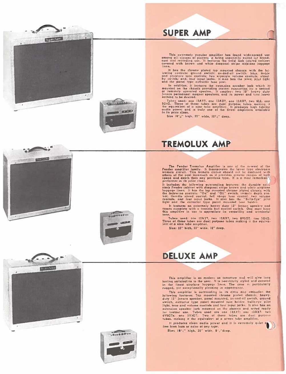
The Deluxe retailed for $129.50
There were several other models of the 'Deluxe' but the 5E3 is by far the most popular. The 5E3 amp kit phenomenon is still going strong so there's lots of new tube amp guitarists that would like a not-too-technical explanation of how the amp works, what each component does, and how changing those components will affect the amp's voice.
I recommend you take a look at my How Tube Amps Work and How Vacuum Tubes Work webpages for a detailed explanation how vacuum tubes work in the very simple Fender 5F1 Champ guitar amp. I won't be going over tube theory and other introductory material here so check it out if you have trouble understanding this webpage. For information on the evolution of the Fender Deluxe and Deluxe Reverb circuit see this. If you like to mod your amps check out my 5E3 Modifications webpage. I also have a page dedicated to the magical 5F6-A Bassman amp.
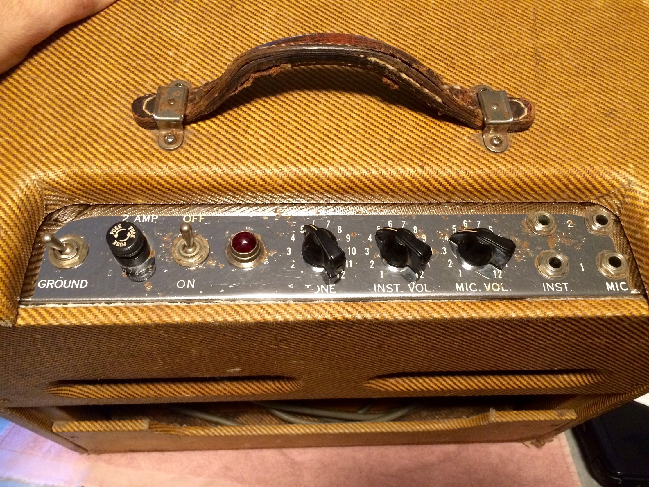
The 5E3 Chassis
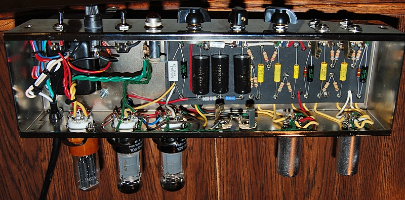
Controls on top, Circuit Board inside, tubes on bottom right to left: V1 Preamp, V2 Preamp & Phase Inverter, V3 and V4 Power Tubes, and V5 Rectifier Tube at far left. The Power Transformer and Output Transformer are attached to the other side of the chassis. Photo and chassis by Bob Arbogast.
Jump down to the Original 5E3 Photos Section to see what a real 1957 5E3 looks like.
Some of the elements that give the 5E3 Deluxe such a unique voice are its funky interactive volume and tone controls and it's raw, deep voice. Both volumes and the tone controls all interact to create some unique tones. Its rawness comes from both preamp gain stages having bypassed cathodes for maximum gain and with no negative feedback loop breakup comes on early. This leads to little headroom, early dirt and a lazy transition from clean to distortion.
The 5E3's very large coupling and bypass capacitors give the amp more bass response than most but this can lead to boominess and 'farting out'. Amplifying all those low frequencies uses a lot of power and can overwhelm the power supply circuit which leads to voltage sag, output volume compression and 'note bloom.' The relatively small output transformer also contributes to output volume compression. Its cathode biased power tubes sound rounder, tubey and warm compared to more modern fixed bias amps. Its old school, almost no gain cathodyne phase inverter doesn't drive the power tubes as hard as amps with a long tail pair phase inverter. From a modern perspective the 5E3 Deluxe has many design 'defects' but they come together to create a unique and beloved tone that's still gaining in popularity.
We'll start the analysis of the 5E3 Deluxe with my annotated versions of the original Fender schematic and layout diagrams for a broad overview of the amp's function then we'll dive deeper and examine individual components and their value tweaking.
The 5E3 Deluxe Schematic with Signal Flow and Annotations
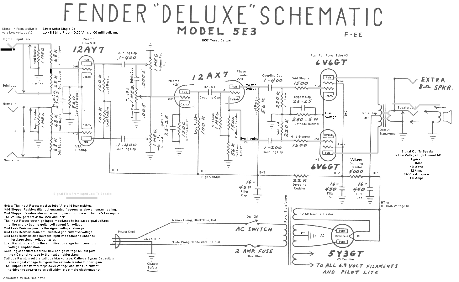
Click the image to view the full size (readable) annotated schematic. A pdf version is here.
The amp's signal flow in the schematic above is shown by the thick grey line from the input jack at upper left to the speaker at upper right (to see the larger, readable version of a diagram on this page just click on the diagram). The very low level AC signal voltage from the guitar's coils enters the amplifier at upper left through one of the 4 Input Jacks. Typical signal level from the guitar pickup coils is about 0.1 volt AC rms but can vary greatly due to the number of pickups, their design and of course how and what is played on the guitar. Quiet jazz played on a guitar with a vintage single coil can produce signals below the single digit millivolt range (0.001v).
The 5E3 has 2 channels, the Normal and Bright Channel. The Bright Channel is brighter because of the addition of a single component, the Bright Capacitor or Brite Cap, which allows high frequencies to bypass the Bright Volume control at lower volume settings. The lower the volume the more highs are bypassed so the Bright Channel is usually preferred for lower volume playing. At max volume the Bright Cap does nothing and the Bright and Normal Channels are identical. The original Fender Bright Cap was 500 pF (pico Farads) but modern standard cap values have made it convenient to use an equivalent 470pF instead. Using a larger value Bright Cap will allow lower frequencies to pass around the Bright Volume control. Using a smaller value Bright Cap will raise the cutoff frequency so less mids would be affected. The Fender 5F6A Bassman used a tiny 100pF Bright Cap so only very high freqs were passed around the volume control. Many modern guitar amps use a mid size 250pF Bright Cap.
The 5E3 Deluxe is famous for it's control interaction. Both volume controls and the tone control all interact with one another even when only one channel is in use. Changing the volume level of the unused channel will alter the tone and breakup of the channel in use. Both volume controls alter how the tone control functions. When the 5E3's Bright channel volume is turned full down its bright cap is connected directly to ground on one end and connected to the bright end of the tone pot on the other. The bright cap then acts as a high freq tone cap that bleeds high freqs to ground. It's not a huge effect but the brightest setting on the tone control moves to less than max on the tone dial. This only occurs when the Normal channel is in use, the Bright channel does not suffer from this control quirk. It's another reason (besides the bright cap) the Bright channel is brighter than the Normal channel.
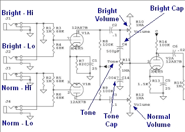
The unused channel volume pot and 100k plate load resistor change the load on the channel in use and therefore affect the gain. The unused channel load can run from 100k at max volume to 1M at min volume. Turning the unused channel volume full down offers up the most preamp gain.
To get the most out of the 5E3 you must play around with all three controls--especially at high volume levels. This is where much of the 5E3 Deluxe's magic resides. Here's an informative quote on setting the controls from clintj, "So, one setting combo that gets me a good amount of warm breakup is this: in-use volume control on 8 or 9, unused volume set on 4, tone set to at least 9. Adjust your unused volume down for more dirt, up for less, zero should get you in Neil Young territory."
Each channel has two input jacks, a Hi and Lo. The Lo jacks' inputs run through a voltage divider formed by the two 68K Grid Stopper resistors which cuts the guitar signal in half (-6dB). If you find that you prefer the Lo input jacks you should consider using the Hi jacks and just turn down the volume on your guitar which gives you the same signal level but you'll have control at the guitar. You should also try "jumpering" the channels together. Plug a short cable into two jacks in the normal and bright channels for a thicker tone that's paralleled through both channel's preamps (example: guitar is plugged into Bright Hi jack then jumper from the Bright Lo jack to the Normal Hi jack). For the graduate level explanation of how the jacks work and how jumpering the two channels together works see this.
Jumpering Channels
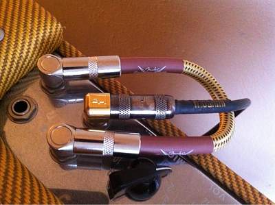
Bright - Hi input used with 6" patch cable between Bright - Lo and Normal - Hi. Photo by sookwinder.
Each channel has an Input Resistor on its Hi Input Jack. The Input Resistors set the amp's input impedance and they act as tube V1's grid leak resistors. For best signal voltage transfer from guitar to amp you want a low impedance from the guitar and a high impedance for the amp (at least 10 times more impedance for the amp is a guide called "the rule of 10"). This intentional impedance mismatch trades guitar pickup coil current for voltage--this is called impedance bridging. 1 megaohm is a standard value for most all guitar amps so there's no reason to tweak its value. A higher value would add impedance but also add noise. A lower value would decrease noise but reduce the voltage signal from the guitar. Some high gain amps use lower value grid leak resistors to intentionally attenuate the signal to control gain between amplifier stages.
In the 50's and 60's carbon composition resistors were used and if you want your amp to look 'period correct' then use them but metal film resistors are over 10 times quieter than carbon comp so use them if you want the best quality audio and lowest noise. Resistors generate the white noise hiss you hear when the amp is turned up to max with no guitar plugged into the amp. The input and grid stopper resistors are a good place to use metal film resistors because their hiss will be amplified by every gain stage.
Grid Stopper resistors help stabilize the amplifier by removing much of the audio signal above human hearing. [Bonus info: The Grid Stoppers also act as 'mixing resistors' to prevent interaction between two simultaneous Hi and Lo inputs like two guitars or a guitar and microphone] The Hi input uses both 68k grid stoppers in parallel so the grid stopper resistance is actually 34k. Grid stop resistors on the first amplifier stage do remove some high freqs from the guitar signal so some modern amps use smaller grid stoppers and some amps do without them altogether. You can use an alligator clip wire to jumper around the grid stopper resistors to try the amp with lower or no grid stopper resistance but the difference is very subtle and only affects very high frequencies but it may add some "sparkle." The optimal location for a grid stopper resistor is on the tube grid (input) pin itself so there's no bare wire after it to act as a radio antenna to pick up radio frequency interference (RFI).
5E3 Layout with Signal Flow and Annotations
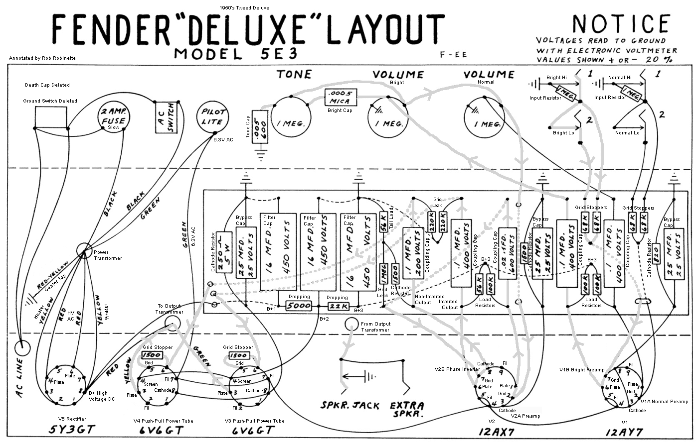
Click the image to view the full size (readable) annotated layout. Notice how convoluted the signal path (thick grey lines) is compared to the schematic. A schematic shows electrical flow while a layout diagram shows the physical location of the amp's components.
Modern 5E3 Deluxe Layout
Click the image to view the full size layout diagram. Click here for hi res pdf. Click here to download the DIYLC file so you can modify this layout diagram yourself.
Layout Diagram Notes:
The Input Resistors act as tube V1’s grid leak resistors.
The volume pots act as the tube V2A grid leak.
Load Resistors transform the amplification stage from current to voltage amplification.
Coupling capacitors block the flow of high voltage DC but pass the AC guitar signal voltage to the next amplifier stage.
Cathode Resistors set the cathode bias voltage.
Cathode Bypass Capacitors allow signal voltage to bypass the cathode resistor to boost gain.
The Output Transformer steps down voltage but steps up current to drive the speaker voice coil which is a simple electromagnet.
After going through the grid stopper resistors the audio signal flows down the wire to the preamp tube's pin 2 (control grid), which is the entry to the 'A' half of the preamp tube (V1A). It's called V1A because tubes were called 'Valves' and this is tube number 1 and we're using half of the tube, the 'A' triode. A triode has three electrodes, a grid, cathode and plate (anode).
12AY7 is the type of tube and it's really two tubes in one (dual triode). The grid is the 'control valve' that controls the flow of electrons through the tube. The AC guitar audio signal charges the grid positively and negatively as it alternates. A positive grid will allow electrons to flow from the cathode, through the grid to the plate. A negatively charged grid will block the flow of electrons through the tube. See How Tubes Work for more info.
Notice that tube V1 has only one cathode resistor valued at 820 ohms. It is shared by both triodes (both halves) of V1 so the cathode resistor is approximately half the value of a cathode resistor used for a single triode such as V2A's 1.5k cathode resistor. Two triode circuits sharing one cathode resistor will pull twice the current through it so you have to cut the resistance in half to get the same voltage drop across the resistor. The voltage drop across the cathode resistor puts the cathode at a positive voltage compared to the control grid (normally around +1.7 volts DC). This voltage difference is the triode's bias. Some modern high gain amps bias their preamp triodes cooler using a 2.7k cathode resistor or bias it hotter with an 820 ohm resistor. Both will reduce headroom and boost preamp distortion. Increasing the cathode resistor value also reduces gain and decreasing it will boost gain.
The hottest bias for a preamp gain stage I have ever seen in a commercial amp is an 820 ohm cathode resistor (not shared). The coldest bias I have seen is a 39k cathode resistor in a Soldano high gain amp. The very high value cathode resistor is designed for early clipping to intentionally generate preamp distortion. This type of preamp stage is called a Cold Clipper and was first used in the Marshall 2204 amplifier.
The 5E3 uses a 12AY7 preamp tube for the first gain stage. You can substitute a higher gain 12AX7 to boost amplification, reduce headroom and increase breakup and distortion. The preamp tube amplifies the guitar audio signal then sends it out pin 1 (plate) to a coupling capacitor or 'cap.' Coupling caps are sometimes called 'blocking caps' because they block DC (direct current) voltage. DC flows in only one direction where AC (alternating current) alternates its direction of flow--the electrons actually change direction and move back and forth through a circuit.
High voltage DC power used by the tube is brought in through the load resistor. Load resistors change the amplification stage from a current amplifier to a voltage amplifier. Many modern amps have load resistor bypass capacitors to remove frequencies above human hearing to stabilize the amplifier and prevent oscillation in high gain amps. You can also remove "ice pick highs" with a load resistor bypass cap.
The wire between tube pin 1 (plate) and the load resistor carries up to 250 volts DC. This wire carries the AC audio signal out while simultaneously bringing in the high voltage DC power the tube needs to function. Coupling capacitors allow the AC audio signal to pass through but block the high voltage DC and keep it from flowing into the following amp stage.
How capacitors block DC but let AC pass: Caps are actually made with sandwiched conductive plates but I like to visualize them as having a stretchable rubber membrane inside that blocks the flow of electricity. When voltage is applied to a capacitor the 'rubber membrane' stretches and bulges as electrons try to flow through it. The higher the voltage the more the membrane bulges. If you quickly reverse the capacitor's voltage polarity it will go from bulging one way to bulging the other way. This is what a small AC signal does--it stretches the 'membrane' back and forth as the voltage alternates which allows electrons on both sides of the capacitor to move back and forth (alternate) but a constant DC voltage that is trying to flow in one direction will be blocked by the membrane.
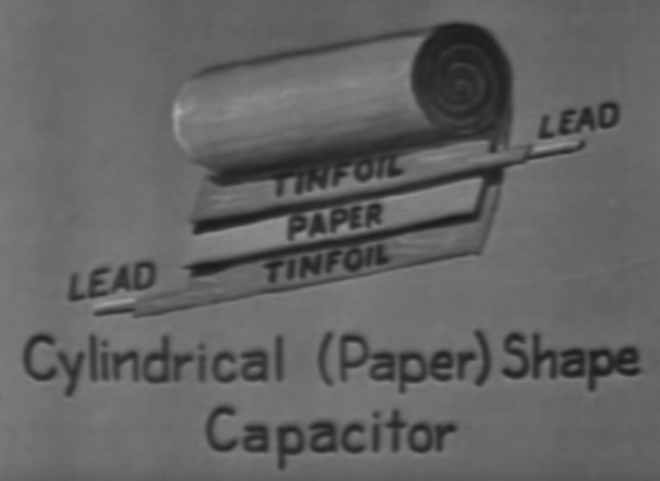
Capacitors are made of two conductive plates separated by an insulator or dielectric. Common dielectrics are mica, polypropylene, ceramic, paper and even oil.
The Fender 5E3 Deluxe uses very large value .1uF (micro Farads) coupling capacitors which allow low frequencies to flow through the amp. These low frequencies use a lot of power and cause the 5E3's infamous "loose low end" and can lead to severe blocking distortion known as "farting out." Reducing the value of the coupling caps will filter out some lows and tighten up the amp and make the amp more humbucker pickup friendly. The overdrive tone will also tighten up. Modern, high gain amps use extremely small coupling caps (0.0022uF) to reduce bias drift, blocking distortion and keep the overdrive tone tight. See my Tube Amp Overdrive page for more info. Some people lower the value of the 5E3 coupling cap in only one channel and leave the other channel alone so you can choose between standard Deluxe or a tighter, more modern tone (see the Voice a Lead Channel mod). Smaller coupling caps can also improve the way the 5E3 works with FX pedals, especially gain boost, delay and reverb pedals.
Another way to trim the 5E3's low end 'fat' and tighten up the amp is to reduce tube V1's or V2A's cathode bypass capacitor. Both have a 25uF 25v cap that is large enough to boost all guitar frequencies but many modern amps use a bypass cap as low as .68uF (680 nano Farads) to boost only mid and high freqs. If you wanted to alter just one of the 5E3's channels you'd have to separate the V1A and V1B cathodes by adding another cathode resistor and bypass cap (see the Voice a Lead Channel mod).
After the coupling cap the guitar audio signal flows to the volume and tone potentiometers (pots). The volume pot acts as a variable voltage divider which when turned down will attenuate the signal voltage. Volume knob left = less voltage signal and lower volume. Volume knob right = more voltage signal and higher volume. Changing the volume pots from 1 meg to 500k (1 million ohms to 500,000 ohms) will send more signal to ground and attenuate the signal path. [Bonus info: The volume pots also function as V2A's grid stopper and grid leak resistors]
The tone pot in combination with the tone capacitor create a variable RC (resistance capacitance) low pass filter which removes high frequencies by shunting them to ground. Using a higher value tone cap will lower the cutoff frequency of the tone control so it will affect more mid frequencies. Reducing it will raise the cutoff frequency and affect less mid freqs.
The guitar signal next flows to tube V2A's pin 7 (grid). This stage acts as the second gain stage which boosts the guitar signal voltage. The audio signal leaves tube V2A via pin 6 (plate) and flows to another coupling cap that blocks DC. The signal then flows to V2B, the cathodyne phase inverter where the guitar signal is split into two streams for the two power tubes. The signal enters at V2B's grid and flows out its plate to a coupling cap and on to power tube V3's grid. This signal is inverted compared to the phase inverter input. The signal also flows out V2B's cathode to a coupling cap and on to power tube V4's grid. This signal is not inverted so the two signals flowing to the power tubes are 180 degrees out of phase--mirror images of one another--one is inverted and one isn't. Unlike the 5F6A Bassman's long tail pair phase inverter, the 5E3's cathodyne phase inverter barely amplifies the guitar signal. It's differential gain factor is always slightly lower than 2. If you upgrade the 5E3 to run big 6L6 power tubes the cathodyne phase inverter won't be able to drive them to full distortion the way a long tail pair phase inverter can.
After the phase inverter the guitar signal flows through another coupling cap to block high voltage then to the power tube grid stopper resistors. Like the preamp grid stopper resistors they help filter out noise above human hearing to prevent oscillation but they also perform another important function, they help control blocking distortion to keep the overdrive tone sweet even when pushed very hard. Like all grid leak resistors you can use the power tube grid leak resistors value to control the input signal voltage. A larger value grid leak will cause less signal attenuation and a smaller value will increase attenuation. Typical power tube grid leak values are 100k and 220k.
The power tubes, V3 and V4, are sometimes referred to as the output tubes. While the preamp tubes have three electrodes: Cathode, control grid and plate (a tube with 3 electrodes is called a triode) the power tubes are pentodes with five electrodes: Cathode, control grid (g1), screen grid (g2), suppressor grid or beam forming plates (g3) and plate. The screen grid is held at a constant, high positive voltage to help pull free electrons from the cathode, through the control grid to the plate. The suppressor grid helps prevent electrons from bouncing off the plate. It is tied directly to the cathode.
Although the 5E3 doesn't have them, screen grid resistors are used in most amps to prevent tube damage from excessive screen grid current. These resistors are usually between 470 to 1500 ohms and rated for 3 or 5 watts of heat dissipation. The 6V6GT is a beam pentode and therefore flows little screen current so the 5E3 can get away with running without screen grid resistors. But if you want to run non-beam, true pentodes like the EL34 then you should install 1k 5 watt screen resistors. Screen grid resistors will also increase the screen voltage drop when screen current flows which will increase the amount of power tube distortion caused by screen voltage drop. Adding a 470 ohm 3 watt resistor to the 5E3 can add sweet sounding power tube distortion so it is a modification to consider.
The power tubes are the final stage of amplification. Where the preamp tubes are voltage amplifiers, V3 and V4 are power amplifiers (power = voltage x current) and their output is expressed as watts. The guitar signal enters at pin 5 (control grid) and leaves via pin 3 (plate) and flows through the output transformer (OT).
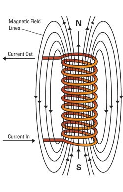
The output transformer's primary and secondary windings are really just two wire coils wrapped around an iron core. The input, or primary coil winding uses electric current flowing through the coil to generate a magnetic field or flux. This magnetic field fluctuates with the AC signal voltage. The magnetic flux flows around the transformer iron core to the secondary coil which generates a voltage in the secondary coil winding. You can alter the voltage and current from primary to secondary by changing the ratio of coil wraps from primary coil to secondary.
Transformers
![]()
Current flowing into the primary winding induces magnetic flux flow around the transformer core which in turn induces an electric current in the secondary winding. Put fewer wire wraps on the secondary (output) winding and its voltage will decrease (step down) but its current will increase. Most guitar amp transformers are of the 'shell' type (bottom of diagram) and made with laminated iron magnetic cores.
Example: The primary winding has 200 wraps of wire in its coil and the secondary has 100 wraps. If a 10 volt 1 amp alternating current is applied to the primary winding the secondary will generate 1/2 of the voltage but twice the current so 5 volts and 2 amps would be put out by the secondary winding. This is what an amplifier's output transformer does, it steps down the signal's voltage but steps up the current because the speaker's voice coil needs current to move the speaker cone.
At high volume the 5E3's output transformer reaches saturation which tends to compress the signal. Once saturated an output transformer can't flow any more flux or get any louder so loud notes are capped but softer notes are still amplified so there's less volume difference between loud and soft guitar notes. Upgrading the 5E3 to a larger, higher watt rated output transformer will boost maximum volume and reduce compression (the output will be more dynamic, accurate and solid state sounding)--but some of the Deluxe's magic lies in its high volume compression.
The output transformer's primary takes in a high voltage, low current signal (high impedance) and puts out a low voltage, high current signal (low impedance). Typically about 320 volts of swing from the power tube plates flow into the output transformer primary and about 12 volts AC flows out the secondary through the blue wire to the speaker jack and on to the speaker.
The speaker jack has a built in switch that grounds the output transformer's secondary when no speaker is plugged in. It does this because if you power up the amp with no speaker connected the output transformer will generate very high voltage in the secondary winding and fry itself if it sees an open circuit. The ground switch on the jack gives the transformer secondary a closed, short circuit which it can handle much better than an open circuit. Always have a speaker connected to a tube amp when you power it up. The aux jack is tied directly to the main speaker jack's tip and ground. Because of the main jack's ground switch you must have a speaker plugged into the main jack for the aux jack to function. You should use an 8 ohm aux speaker along with the cab speaker which will give the amp a 4 ohm load which Fender considers safe for the amp. A 4 ohm aux speaker will give the amp a too low load which will reduce output and stress the power tubes.
From the speaker jack the signal moves on to the speaker. The alternating current audio signal flows through the speaker's voice coil which generates a magnetic field. The voice coil is simply a single wire wrapped into a coil as shown below. The magnetic field created by the voice coil is either attracted to or repelled by the speaker's magnet. Positive voltage in the voice coil generates a repulsive magnetic force and the speaker coil and cone moves outward away from the speaker magnet. Negative voltage generates an attractive magnetic force and pulls the speaker cone inward. The speaker cone alternates between moving outward and inward as the guitar signal voltage alternates between positive and negative.
Speaker Voice Coil is an Electromagnet
Electric current flowing through the speaker's voice coil generates a magnetic field. When the audio signal electric current reverses the magnetic field also reverses causing attraction and repulsion to the speaker magnet.
This in and out movement of the voice coil and speaker cone creates air pressure waves that our ears perceive as sound--the sweet sound of electric guitar. For every movement of a guitar string the amplifier generates a corresponding movement of the speaker cone. When the speaker cone moves outward a positive air pressure wave is created and when the cone moves inward a negative (low pressure) wave trough is generated. These air pressure waves move our ear drums in and out. The ear drum movement is translated into neuron activity which is sent to the brain where pleasure is created, thus electric guitar + amp = pleasure.
Speaker
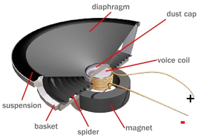
The 'voice coil' is an electromagnet that interacts with the speaker magnet. The 'spider' supports the voice coil but allows it to move in and out freely.
So the main purpose of the 5E3 guitar amplifier is to take the tiny electrical signal generated by the guitar's pickup and make it strong enough to push and pull a speaker cone. The guitar amp is also used to shape the tone and control distortion giving us the clean, mellow sound of jazz guitar or the animal growl of hard rock. Distortion is an important part of guitar amplifier design and this is the primary difference between guitar and audio amplifiers. Audio amps are usually designed for absolute minimum distortion. See Tube Guitar Amplifier Overdrive for specific information on how overdrive distortion is created.
5E3 V2A Load Line Chart
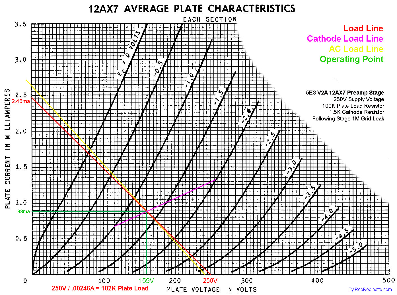
The 5E3's V2A is a very generic gain stage with a nice center bias for maximum headroom and symmetric clipping. Note the color coded legend at upper right. Load line in red, cathode load line in magenta, AC load line in yellow and operating point (bias point) in green. For information on how these lines were charted see How to Draw Load Lines.
Power Supply
Now that we've covered the signal flow I'll go back and cover the other amplifier components that I didn't mention. Wall plug power of 120 volts AC (or 100, 220 or 240 volts AC in other countries) runs through the fuse and on to the power switch. The fuse is a 2 amp slow blow fuse. Slow blow means it won't blow instantaneously when the turn-on power surge runs through it. Sustained current greater than 2 amps is required to blow the fuse.
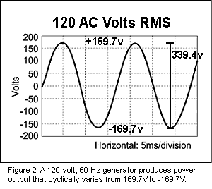
120 AC volts RMS (DC equivalent average) wall power equals 339.4 volts peak-to-peak.
After the amp's fuse and On/Off switch the 120v AC runs to the power transformer (PT), through its primary winding, then back to the wall plug via the white neutral wire*. The power transformer has three secondary windings. The first winding steps the 120v AC up to 650 volts AC. Two other small secondary windings step the 120v AC down to 6.3 volts AC and 5 volts AC (notice all voltages output by transformers are always AC). The 6.3 volts is used to power the pilot light and heat the preamp and power tubes' heater filaments which heat the tubes' cathodes. The 5 volts is used to heat the rectifier tube's cathode.
*Bonus Info: When I first learned that the power transformer primary coil was made up of one long wire that directly connects the 120v hot wire to the neutral (ground) wire I wondered why it didn't short out. The reason is the primary and secondary coils are coupled together by the transformer's iron core. Alternating current in the primary coil creates a magnetic field or flux that is captured by the core. That flux flowing around the core creates an AC voltage in the secondary coil. The load (impedance) placed on the secondary winding by the amplifier is transferred through the core to the primary coil. That impedance keeps the primary coil from "shorting out."
The 650 volts AC power from the power transformer is fed directly into V5, the 5Y3 rectifier tube. V5 is a full wave dual plate rectifier tube that converts alternating current (AC) into direct current (DC), which the amplifier's electronics actually need to function. The power transformer and rectifier tube have internal resistance that cause voltage sag when higher current is demanded. Installing a higher rated power transformer can reduce voltage sag and "stiffen" the amp's tone, make it sound "punchier" and help tighten the bottom end.
370 volts of DC flows out of the rectifier tube's pin 8 (cathode) and is referred to as B+ or B+1 voltage (from old Battery Positive designation). You can raise the DC voltages in the amp by swapping out the 5Y3 rectifier tube for a higher output tube but be careful because your 6V6 power tubes can be damaged by too high a plate voltage. Higher amp voltage tends to increase output power, tighten up the tone and make it "punchier."
The B+1 DC voltage flows to the output transformer's primary winding and to the circuit board's three large filter/reservoir capacitors and two voltage dropping resistors. These resistors and capacitors form RC (resistance capacitance) low pass filters that take the lumpy, pulsing DC output of the rectifier tube and smooth it out--the smoother the better. Any waves or ripples left over in the DC power would be added to our audio signal and heard as 120Hz hum in the preamp and power tubes. The filter caps also act as a power reservoir so the larger the value of the capacitors the "stiffer" the amp sounds because the amp can react to power demands with less voltage sag. Low frequencies demand more power so larger capacitors can really help the low end and prevent "farting out."
Notice the resistors between the filter caps. These are voltage dropping or step down resistors that reduce the 370 volts DC B+1 down to 295 volts DC B+2 then to 250 volts DC B+3. The B+1 voltage from the rectifier is tapped off to feed directly to the output transformer's primary center tap which feeds the power tubes' plates. The 295 volts DC B+2 is connected to the power tubes' pins 4--the screen grids. The 250 volts DC B+3 is used to power the preamp and phase inverter tubes but it's stepped down even more by their load resistors. The filter capacitors and voltage dropping resistors also decouple the three B+ power nodes to prevent interaction, feedback and oscillations between the preamp and power tube. You can raise or lower the B+2 and B+3 voltages by adjusting the value of the voltage dropping resistors.
Now that you know how the 5E3 works let's talk about modifying it.
5E3 Power Transformer Calculations
The following equations and calculations estimate the maximum power use of the 5E3.
5V Rectifier Heater Current
The 5E3 Deluxe's 5Y3 rectifier uses 2 amps of 5V heater current. Other rectifiers: GZ34 uses 1.9 amps and the 5U4 uses 3 amps.
6.3V Heater Current Calculations
Heater current in amps: Preamp tubes: 0.3, KT88/6550: 1.6, KT66: 1.3, EL34/6CA7: 1.5, 6V6: 0.45, EL84/6BQ5: 0.8, 6L6: 0.9, 5881: 0.9
Calculated 6.3V filament current: (2 * 6V6) + (2 * preamp tubes) = (2 * 0.45) + (2 * 0.3) = 1.5A
B+ Current Calculations
B+ current is supplied by the power transformer's high voltage secondary. Preamp tube current is so low it isn't necessary to actually calculate the value so we can simply estimate it at 3ma per triode (2 triodes per preamp tube).
Power Tube B+ Current Calculations:
Transformer voltage: 355-0-355 volts AC RMS. The 0 means the transformer has a grounded 0 volt center tap and the transformer puts out +355v on one wire while simultaneously putting out -355v on the other for a 710v AC RMS voltage wire-to-wire.
Max_Plate_Dissipation in watts from tube data sheets: KT88/6550: 42, KT66: 25, EL34/6CA7: 25, 6V6: 12, EL84/6BQ5: 12, 6L6GC: 30, 6L6WGB/5881: 23, 6L6/G/GA/GB/WGA/5932: 19, Preamp tubes using both triodes as power tubes: 12AX7: 2, 12AT7: 5, 12AU7: 5.5, 12BH7A: 7
Rectifier_Efficiency: Solid state full wave diode: 1.37, GZ34: 1.36, EZ81: 1.30, 5U4B: 1.28, 5Y3: 1.25
Unloaded_B+ voltage = Transformer AC * Rectifier_Efficiency = 355V * 1.25 = 443.8V. This would be the B+ voltage with no preamp or power tubes installed.
B+_Voltage_Drop under load is estimated at 16% = 443.8 * .16 = 71V
How far the B+ drops is dependant upon the output transformer's current rating. A transformer operating near its max current rating can't refill the filter (reservoir) capacitors as quickly as a larger, higher rated transformer so the voltage will drop more.
B+ Voltage = Unloaded_B+ - B+_Voltage_Drop = 443.8 - 71V = 373V
Calculated_Ideal_Load = B+^2 / Max_Plate_Dissipation = 373V^2 / 12w = 11,594 ohms
Notes: Calculated_Ideal_Load is the ideal plate-to-plate impedance of the output transformer. ^2 means squared.
Load = 8,000 The 5E3 standard output transformer is 8,000 ohm primary : 8 ohm secondary
Power_Tube_Power = (Number_Power_Tubes * (B+ – 30)^2) / Load
= (2 * (373V – 30V)^2 / 8,000 ohms = 29.4 watts
Note: Power Tube power use, not power to the speakers. B+ is the max plate voltage and 30V is the minimum plate voltage.
Power_Tube_Current = Power_Tube_Power / B+ = 29.4W / 373V = 78.8 milliamps
Calculated_HT_Current = Power_Tube_Current + Preamp_Tube_Current
= (78.8ma + (3ma * 4) ) = 90.8 milliamps
So a 5E3 power transformer must supply at least 2 amps of 5V rectifier heater current, 1.5 amps of 6.3V current for the tube heaters and 90.8 milliamps (0.0932 amps) of B+ current. It uses 10 watts of 5V, 9.5 watts of 6.3V and 34 watts of B+ for a total of 53.6 watts, less than a 60 watt light bulb.
See my Amplifier Power Transformer Calculations spreadsheet to automate these calculations.
Standard 5E3 DC Voltages
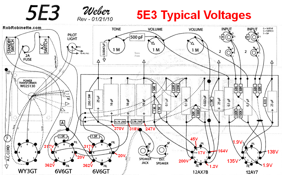
Voltages shown in red are DC.
Typical 5E3 B+ Idle Currents
V1A 1.1ma = 110v drop across 100k plate load resistor = 110v / 100k
V1B 1.1ma = 110v drop across 100k plate load resistor = 110v / 100k
V2A .83ma = 83v drop across 100k plate load resistor = 83v / 100k
V2B .84ma = 47v drop across 56k plate load resistor = 47v / 56k
V3 38ma = 19v drop across 250 ohm cathode resistor / 2 = 19v / 250 / 2
V4 38ma = 19v drop across 250 ohm cathode resistor / 2 = 19v / 250 / 2
Total: 79.9 milliamps
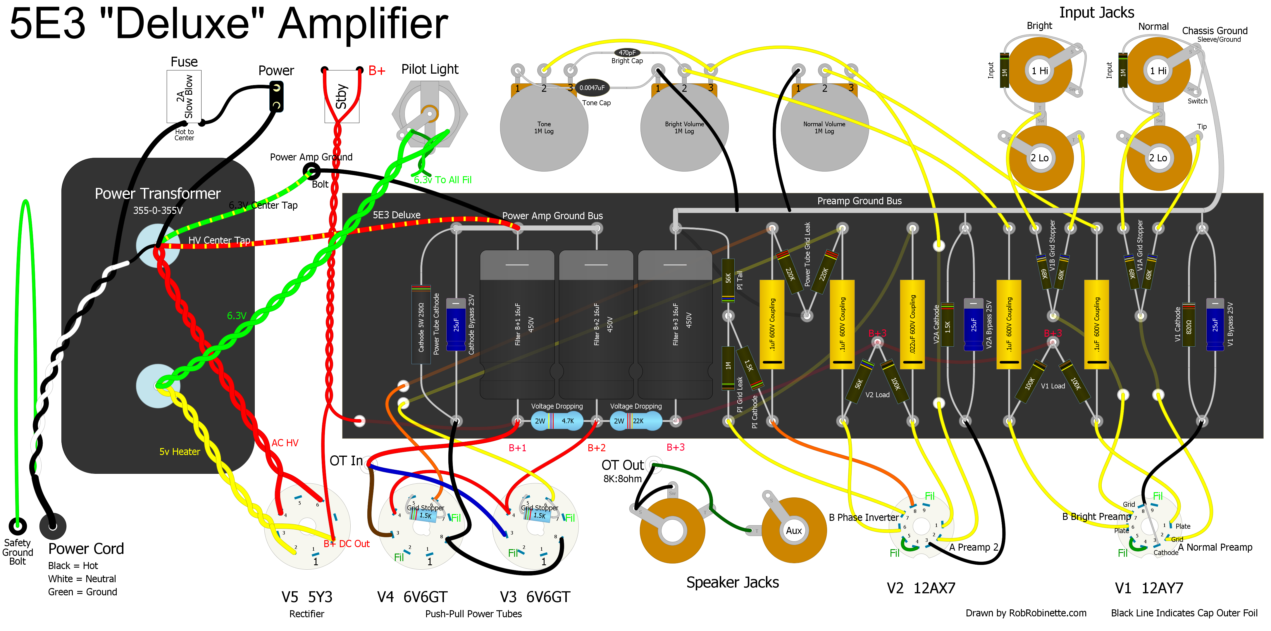
My suggested layouts for a new build 5E3
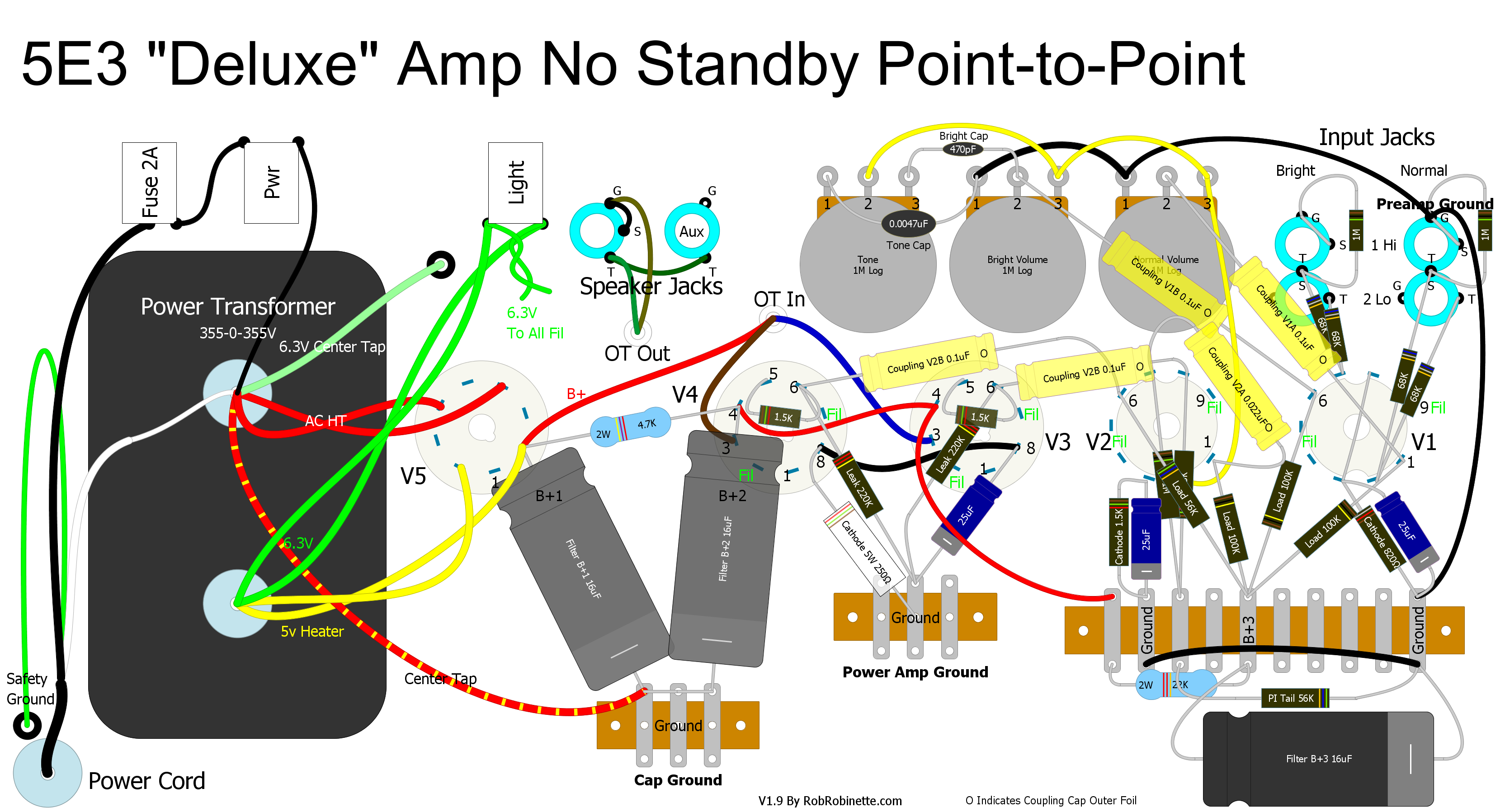
Classic 5E3 Layout
Note the Weber split ground bus, power amp ground on left, preamp ground bus on right.
Optimized 5E3 Layout
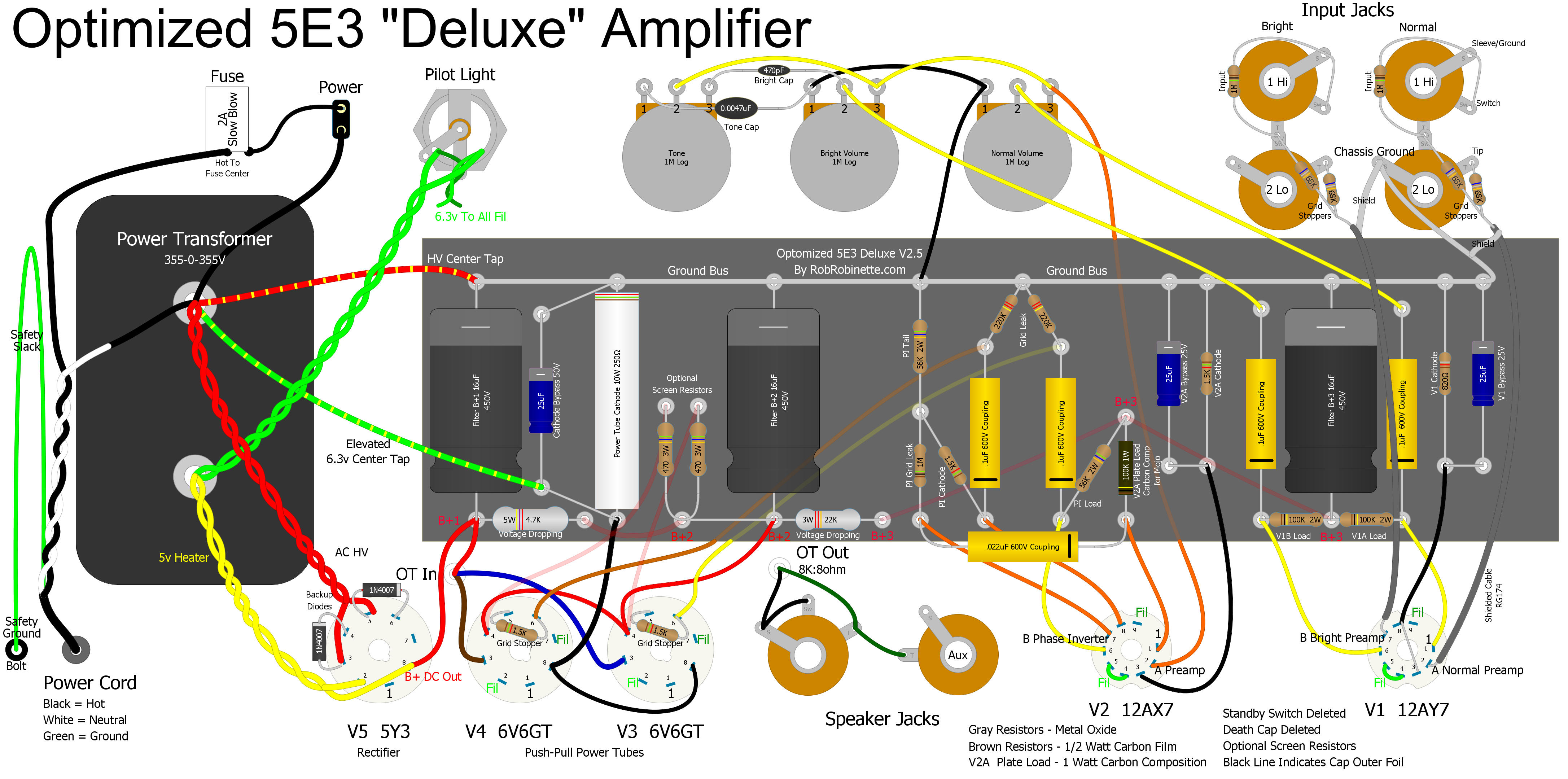
Click on the layout to see the full size image. The pdf is here. Upload the optimized Hoffman circuit board file to the HoffmanAmps.com DIYLC file analyzer to have an eyelet or turret board built for about $20.
This is my take on the best possible layout for a standard 5E3 chassis. This is a basic 5E3 circuit, there are no modifications that will affect the tone. I have deleted the totally unnecessary Standby Switch and Death Cap.
Shielded cable is used to connect the grid stoppers directly (across the chassis) to V1. The cable shield is grounded to an input jack ground tab. The V1 end of the cable is not grounded to prevent a ground loop. A nice, clean option is to use shielded microphone cable which has four conductors and run both input wires through one microphone cable. Shielded cable isn't a necessity in the 5E3 but if you use standard wire I recommend you run it along the chassis floor and below the circuit board to allow the chassis act as a noise shield.
Separate eyelets are provided for the preamp tube cathode resistors and bypass caps. The B+3 filter cap is moved to supply V1 directly. The V2A coupling cap is reoriented to reduce cable runs. Wire routing is optimized for shorter runs, 90 degree wire crossings and maximum separation between grid and plate wires.
The choice of resistor is up to you but I recommend 1 watt metal film everywhere except where noted on the layout. Metal film resistors generate 1/10th the resistor hiss compared to carbon composition resistors but I did follow R.G. Keen's suggestion to use 1 or .5 watt carbon comp resistors on just the phase inverter load and tail resistors for a little carbon mojo. A 10 watt 250 ohm cement resistor is used for the power tube cathode. The plate load resistors are bumped up to 2 watts and the voltage dropping resistors are upgraded to 3 and 5 watts for component longevity.
I employed a unified ground bus that is only grounded at the Normal Low input jack. The power transformer high voltage center tap is connected directly to the B+1 filter capacitor negative terminal to minimize hum. The typical split-bus ground sends all the preamp return current through the chassis. This ground scheme doesn't flow any current through the chassis which any electrical engineer will tell you is a good thing.
The 6.3v center tap is connected to the tube side of the power tube cathode resistor to elevate the reference voltage to reduce hum. If you want to use an artificial 6.3v center tap then I recommend putting the 100 ohm resistors on the V3 power tube socket like this.
I also shortened up the component span to keep from stretching the small component leads so much.
I added optional power tube screen resistors to the circuit board. They are shown "ghosted" on the circuit board between the power tube cathode resistor and the B+2 filter cap. I add them to all my 5E3 builds because they help protect the tubes during heavy overdrive and they sweeten the power tube distortion. If you do want to use them then do not use the red wire that runs from the B+2 cap to the power tube pins 4, use the wires from the top of the screen resistors to pins 4 instead.
The worthless standby switch has been removed which allowed some simplification and optimization of this point-to-point layout. I used a simple three-point grounding scheme with the first two filter caps' ground isolated. The "Cap Ground" and "Power Amp Ground" tag strips are grounded to the chassis. The preamp ground at lower right is grounded through the black wire connected to the Normal Hi input jack at upper right--the tag strip's center ground terminal is not used.
VHT Standard 12 Version of the 5E3 Deluxe
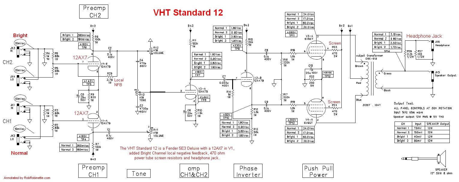
The VHT Standard 12 is a 5E3 Deluxe with a 12AX7 in V1, added V1B Bright Channel local negative feedback (Local NFB center left), 470 ohm power tube screen resistors and headphone jack (upper right).
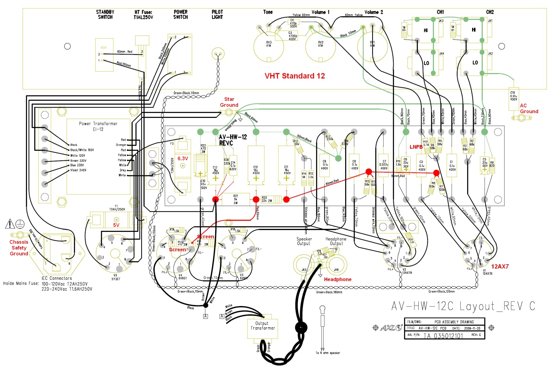
2.7M Local Negative Feedback (LNFB at center right), 470 ohm 2 watt screen resistors on the power tube sockets and added headphone jack circuit (center low). Green wires are ground connections.
The addition of the V1B local negative feedback circuit will slightly reduce Bright Channel gain and distortion and help tame the extra gain from the 12AX7 in V1 (5E3 uses a 12AY7 in V1). Adding 470 ohm power tube screen resistors would sweeten power tube distortion and help protect the tube from screen failure during heavy overdrive. The amp uses a star grounding scheme with isolated Cliff input jacks connected to an AC only ground through capacitor C15. The headphone circuit's 2.2k and 100 ohm resistors form a voltage divider which cuts the amp's output to the headphone by 96%. The headphone output suffers from the lack of speaker tone shaping and breakup. I recommend anyone owning a Standard 12 try a 12AY7 in V1 for a more authentic 5E3 tone.
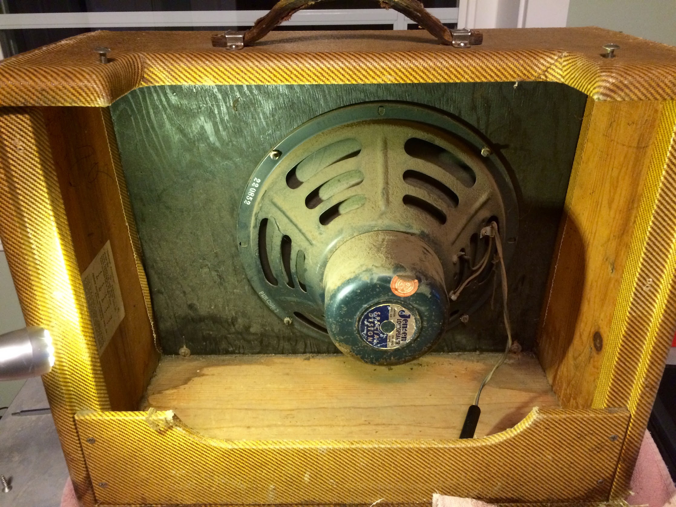
Original 5E3 Deluxe Photos
These pics are from a near virgin 5E3. All photos in this section were generously donated by Keithb7.
Photos by Keithb7.

![]()
![]()
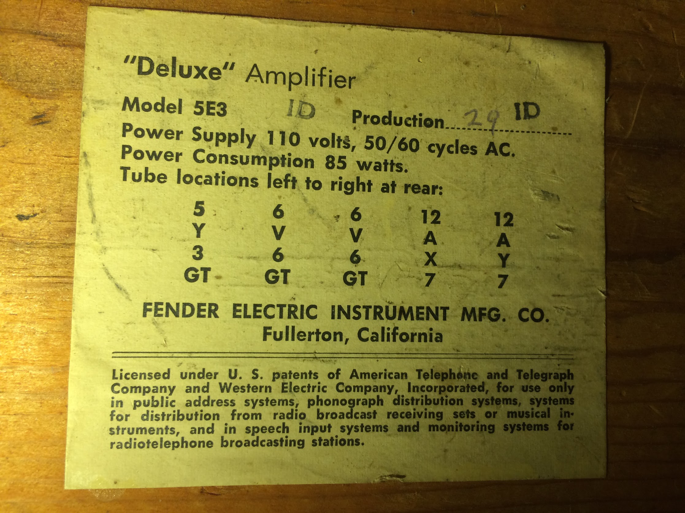
The tube chart inside the cab. See this to make a reproduction chart.
Well that's it for the 5E3 Deluxe. It's a great sounding but simple guitar amp.
Here's a 5E3 Derived Big Bottle Amp From Weber
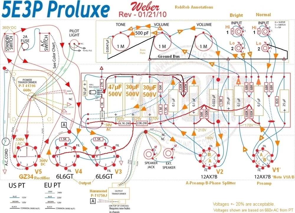
The 5E3P tweed Proluxe features a dual 6L6 tube push-pull output stage and fixed bias. It uses a higher voltage output GZ34 rectifier tube to give the 6L6 power tubes the higher voltage they like. The signal flow is identical to the 5E3 and is shown using orange arrows. Red arrows show the power flow. My first amp build was a BootHillAmps.com 5E3P.
By Rob Robinette
References
RCA Corporation, RCA Receiving Tube Manual, RC30.
Merlin Blencowe, Designing Tube Preamps for Guitar and Bass, 2nd Edition. This is my personal favorite tube amp book.
Merlin Blencowe, Designing High-Fidelity Tube Preamps
Morgan Jones, Valve Amplifiers, 4th Edition.
Richard Kuehnel, Circuit Analysis of a Legendary Tube Amplifier: The Fender Bassman 5F6-A, 3rd Edition.
Richard Kuehnel, Vacuum Tube Circuit Design: Guitar Amplifier Preamps, 2nd Edition.
Richard Kuehnel, Vacuum Tube Circuit Design: Guitar Amplifier Power Amps
Robert C. Megantz, Design and Construction of Tube Guitar Amplifiers
Neumann & Irving, Guitar Amplifier Overdrive, A Visual Tour It's fairly technical but it's the only book written specifically about guitar amplifier overdrive. It includes many graphs to help make the material easier to understand.
T.E. Rutt, Vacuum Tube Triode Nonlinearity as Part of The Electric Guitar Sound
[ How Amps Work ] [ Overdrive ] [ 5E3 Mods ] [ 5F6A Mods ] [ AB763 Mods ] [ DRRI & 68 CDR Mods ] [ How the 5E3 Deluxe Works ] [ How the AB763 Works ] [ AB763 Models ] [ Tube Bias Calculator ] [ Amp Troubleshooting ] [ Deluxe Models ] [ Deluxe Micro Amp ] [ Bassman Micro Amp ] [ Champ Micro Amp ] [ My 5E3 Build ] [ Reverb & Tremolo ] [ SixShooter ] [ Spice Analysis ] [ VHT Special 6 Ultra Mods ] [ Telecaster Mods ] [ Android Tube Bias Calculator App ] [ The Trainwreck Pages ] [ Fender Input Jacks ] [ B9A Prototype Board ]