RobRob Stereo Amp
By Rob Robinette
Have comments or corrections? Email rob at: robinette at comcast dot net
This version of my Stereo Amp can be used with guitar or stereo audio. It has one more gain stage than the audio only amp below in the next section so it can amplify electric guitar as well as mp3/flac audio.
I wanted to build myself a nice, simple little five watts per channel stereo tube amp that would be good at playing stereo music from an mp3/flac player but could also be used for stereo guitar. I decided to go with 6V6 single-ended for simplicity. We end up with a very simple tube amp based on the 1950's Fender 5F1 Champ guitar amp with two 12AX7s, two 6V6GTs, upgraded transformers and an added choke to minimize hum and power line noise. If you don't need the capability to use this amp with guitar then I recommend you skip down to the next section to the even simpler RobRob Stereo Audio Amp (line level and mp3/flac player only). An easy way to use this amp for stereo guitar is to use a stereo FX pedal and run its stereo outs to this amp's two inputs.
Now you know I'm a firm believer in tube amp nonlinear and harmonic distortion. It's what makes our tube amps sound so rich and warm so I decided not to fight THD (total harmonic distortion), but to embrace it. Many audio amps use constant current sources, ultralinear power amps and various other techniques to minimize distortion but I don't want that crap--give me tube simplicity and its sweet warmth of even order harmonics. This is a very simple and very warm sounding amplifier.
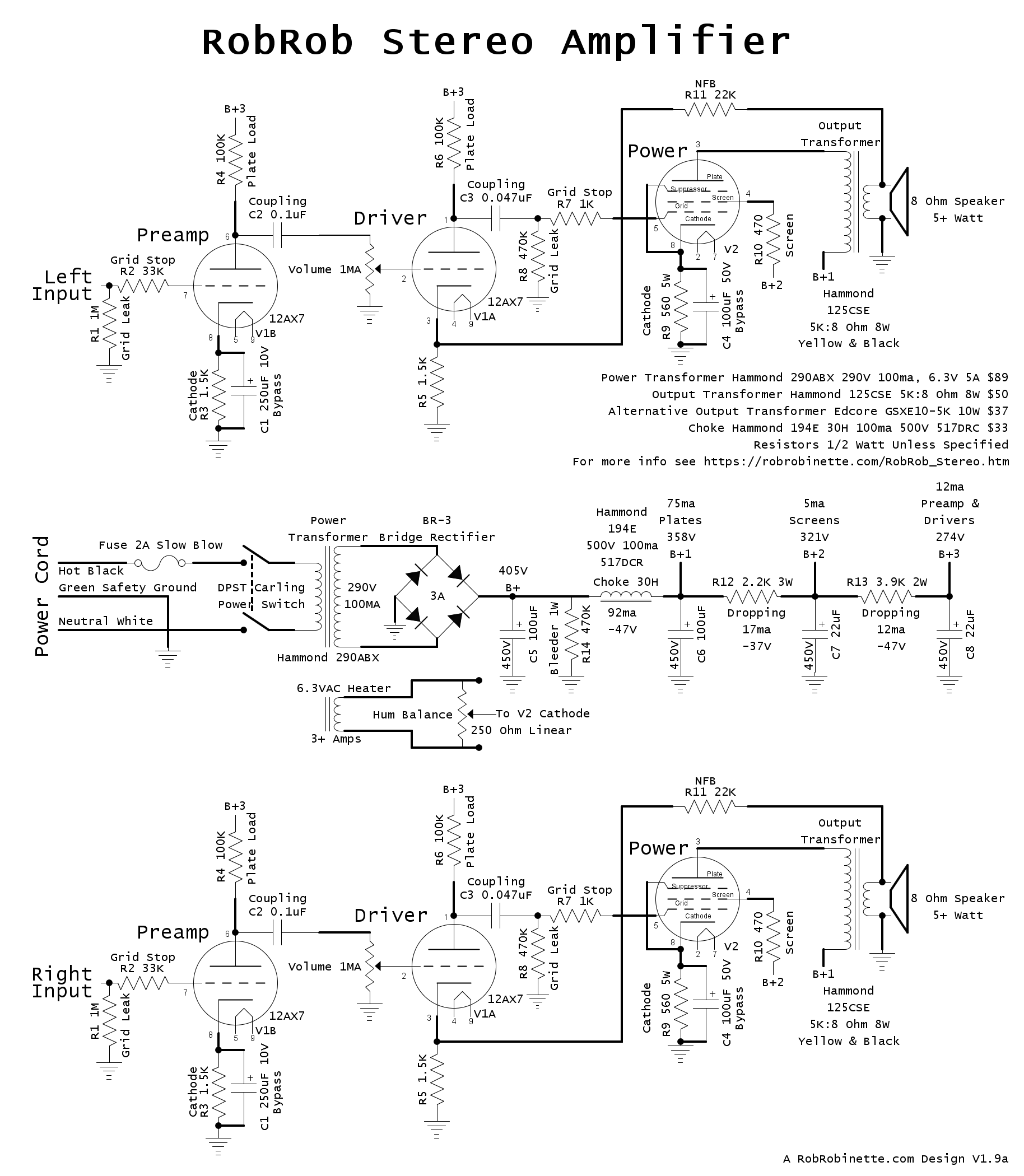
It's basically a dual channel Fender 5F1 Champ with a single power supply. The large 30 Henry choke filters the entire power supply including the power tube plates (B+1) for minimum hum. A humdinger and elevated heater voltage reference also helps minimize 60Hz heater hum. Click the image to see the high resolution schematic. Download the pdf, download the DIYLC file.
The layout diagram is for a Hammond 1444-10825 aluminum chassis at 10" x 8" x 2.5" and is an easy fit.
Transformers are all from Hammond:
290ABX power transformer 290V @ 100ma, 6.3v @ 5A (supports 120 & 240v primary) $89. A transformer with a 270 or 280v secondary would also work in this amp.
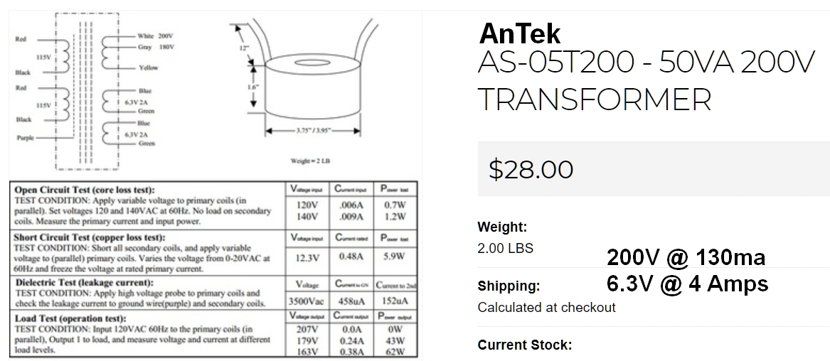
Optional $28 AnTek AS-05T280 toroidal power transformer 280v 90ma (50VA), 6.3v @ 4 amps. It has a 120v and 240v primary and also has a 180v tap in case you want to lower the amp voltages. Another bonus is it only weighs 2 lbs. Size is 3.75" in diameter and 1.6" tall. You can mount the transformer on the top of the chassis and purchase a 105x45mm round transformer cover or leave it exposed.
![]()
125CSE output transformers 5K:8 ohm 8 watt $50 (2 each). A nice option if you can wait the 4 to 8 week build time is the Edcore GSXE10-5K output transformer 5K:8 ohm 10 watt $38. The 5 watt Hammond 125BSE or 10 watt 125DSE can also be used. The 5 watt rated 125BSE will compress at high volume levels and the 10 watt 125DSE will yield maximum volume and fidelity.
194E choke 30H 100ma 517 ohm DC resistance $33. Note the choke's 517 ohms of DC resistance was used to drop voltage. If you use a different choke you may need to add a voltage dropping resistor to get the B+1 voltage down to 360 volts or lower.
3-Lug and 6-Lug terminal strips are from tubesandmore.com. The 3-Lug strips have a grounded center terminal because it is used to bolt the strip to the chassis. The 6-Lug strips have the second lug grounded (second lug marked with ground symbol in the layout below).
The speaker outputs can be setup with speaker binding posts as shown below in the layout or you can use standard guitar amp Switchcraft 12A jacks. I like to use these style dual speaker binding posts:

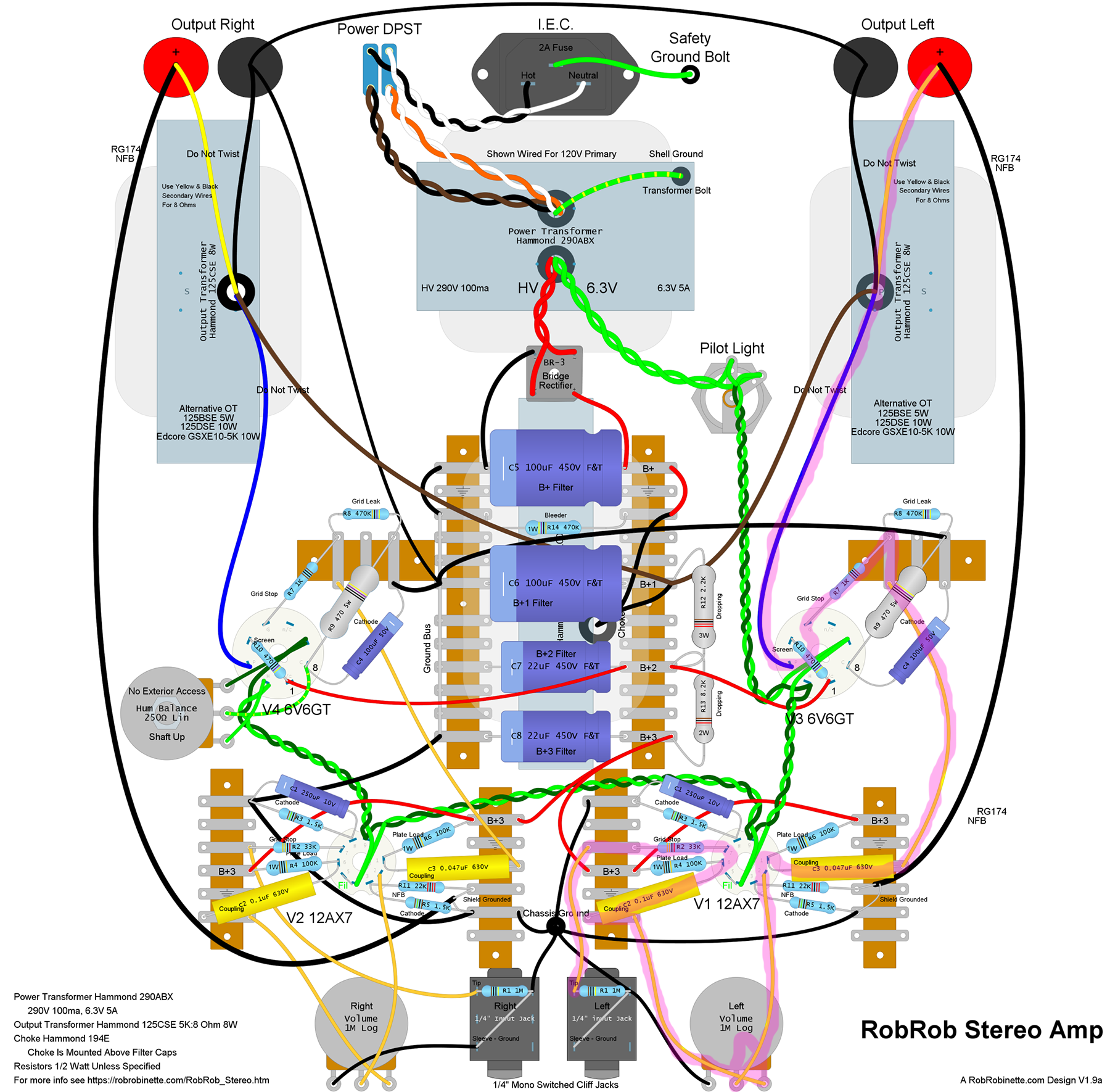
RobRob Stereo Amplifier
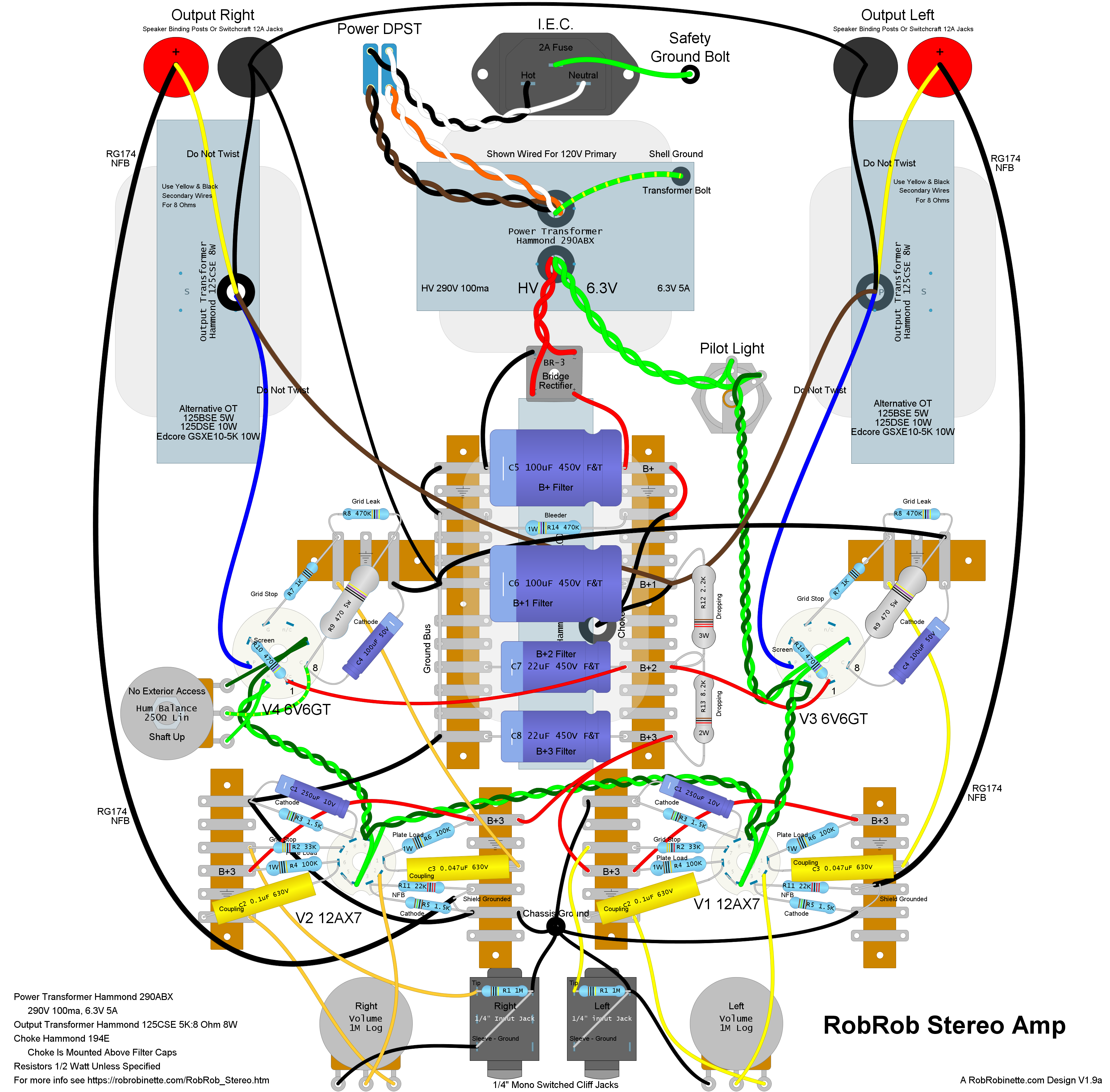
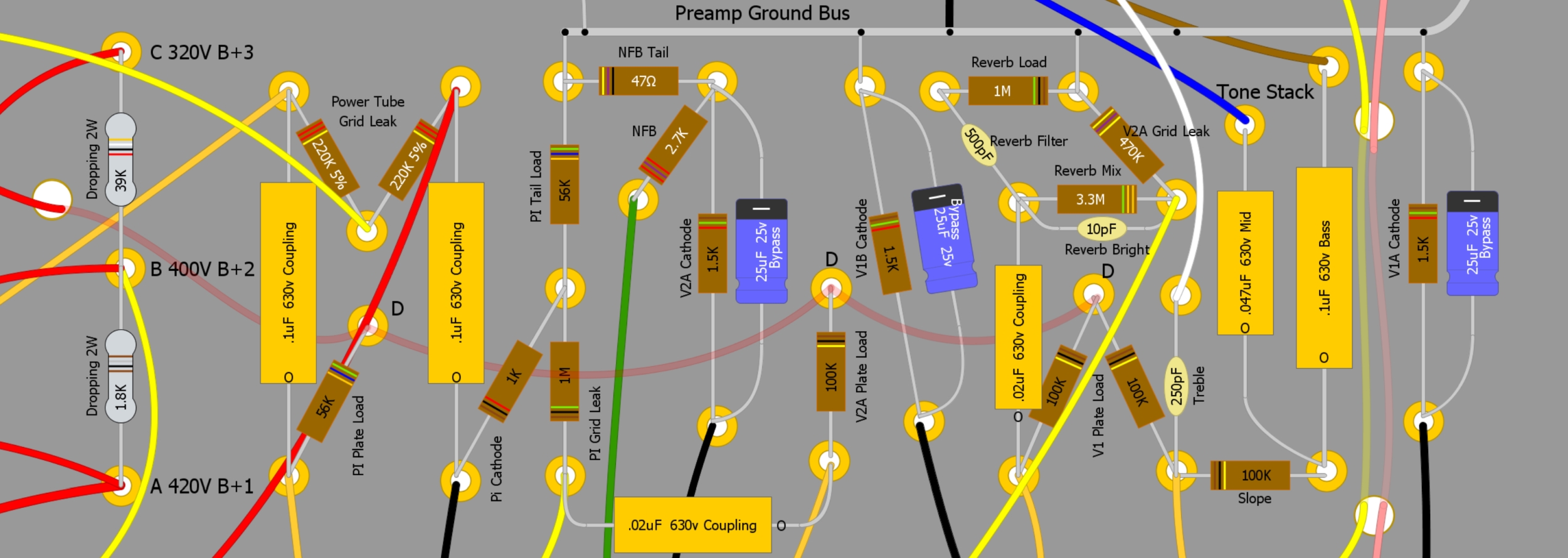
This layout is for a 10" x 8" x 2.5" Hammond 1444-10825 aluminum chassis. View of the amp from the underside of the chassis so left and right are reversed. It's such a simple amp that point-to-point wiring made sense. The three transformers and choke are mounted on top of the chassis so the interior of the chassis will not look quite as chaotic as the layout above. The long terminal strips in the middle are two 6 lug terminal strips joined together. The hum balance pot is mounted inside the chassis and is not accessible from outside the chassis (you don't want people turning that knob willie -nillie). The long NFB runs from the positive speaker posts to V1 and V2 need to use shielded cable such as RG174. Ground the cable shield at only the V1 end to prevent a ground loop. Note how the power tubes, V3 and V4 have their heaters wired out of phase. This will make any heater hum from the two stereo speakers out of phase and the hum will tend to cancel. Click the image to see the high resolution layout. Download the pdf, download the DIYLC file.
For the build sequence I recommend you start by drilling the chassis for the IEC socket, power switch, volume pots, input jacks, speaker binding posts, bridge rectifier bolt, chassis ground bolt, chassis safety ground bolt, transformer mounts and pass-through holes and tube mount holes. Install the tag strips, tube sockets, power switch, volume pot, hum balance pot and bolt down the bridge rectifier directly to the chassis for cooling.
Mount the transformers and choke, add grommets to the transformer and choke pass through holes and feed their wires through to the chassis interior.
Wire the 6.3v heater wires next including the hum balance pot and pilot light. I like to use 22 gauge wire for the heaters because it is easy to work with and has plenty of current carrying capacity. Twist the heater wires and keep them down against the chassis to minimize 60Hz heater hum. Then install the filter caps, other components and wire the rest of the amp.
If you would prefer a tube rectifier you can use an EZ81 and follow the rectifier layout for the Bassman Micro. The EZ81 uses 6.3v heaters so the 290ABX power transformer's lack of a 5v secondary is not a problem.
I recommend following my Amplifier Startup procedure to safely add power for the first time. Resistor R14 is a bleeder resistor and it should drain the filter capacitors upon shutdown but you should always verify the caps are discharged before working inside the chassis.
If you have problems see my Tube Amp Troubleshooting webpage.
Since this amp uses negative feedback (NFB) there is a 50-50 chance you will get a very loud positive feedback squeal when you first power up the amp. If this happens simply shut down the amp, verify the filter caps have zero voltage (they should since resistor R14 will bleed the caps) and swap the output transformer blue and brown primary wires (swap both sets).
To adjust the humdinger hum balance pot you turn the amp up to full volume with nothing plugged in, then adjust the pot for minimum hum. If you don't hear a difference then leave the pot in the middle of its travel.
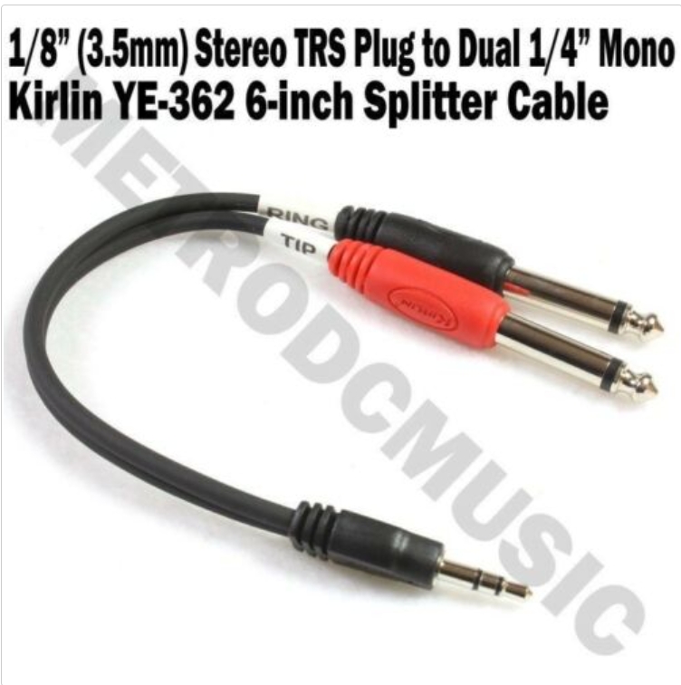
Use a 1/8" (3.5mm) Stereo TRS plug to dual 1/4" mono (guitar) plug adapter to play your mp3/flac player through this amp.
If you would like to use this amp with a pair of headphones you can simply connect two 10 ohm, 10 watt resistors across each pair of speaker out terminals (+ to -). This will show the amp an approximate 8 ohm load when paralleled with the headphone load which can be anything from 8 to 600+ ohms. Then connect a headphone out adapter to the speaker terminals. I have done this with several tube amps and you would be surprised how good it sounds.
Bill of Materials
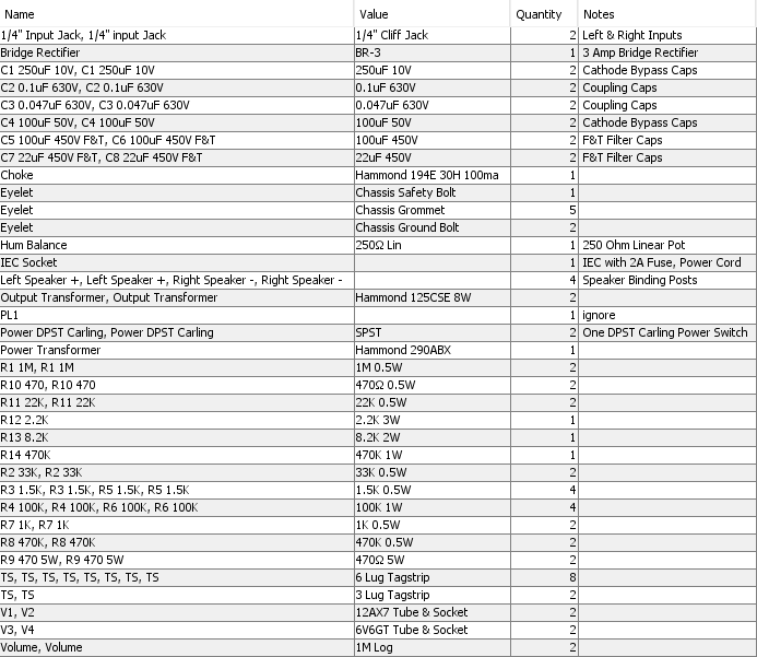
You will also need a 10" x 8" chassis.
Signal Path
Signal enters at the left input jack at the bottom, flows through the R2 grid stop resistor to the V1B grid, then out the plate through the C2 coupling cap to the volume pot then to the V1A grid. The signal leaves V1A through its plate and C3 coupling cap to the R7 power tube grid stop resistor. The signal comes out the V3 plate through the output transformer primary then out the secondary to the speaker binding posts.
RobRob Stereo Audio Amplifier
This even simpler version of the amp is designed exclusively with line level or mp3/flac players in mind so I only needed one triode gain stage per channel to drive the 6V6 power tubes. We end up with a very simple stereo tube amp with one 12AX7 and two 6V6GTs.
This simple little circuit is based on the 1950's Fender 5F1 Champ but with one gain stage deleted, upgraded transformers and an added choke to minimize hum and power line noise. I also added a blackface style negative feedback loop so I could use a fully bypassed cathode on the V1 driver stage to maximize gain. The 100/1.8k ohm NFB voltage divider will give us slightly less NFB than a blackface Reverb Deluxe.
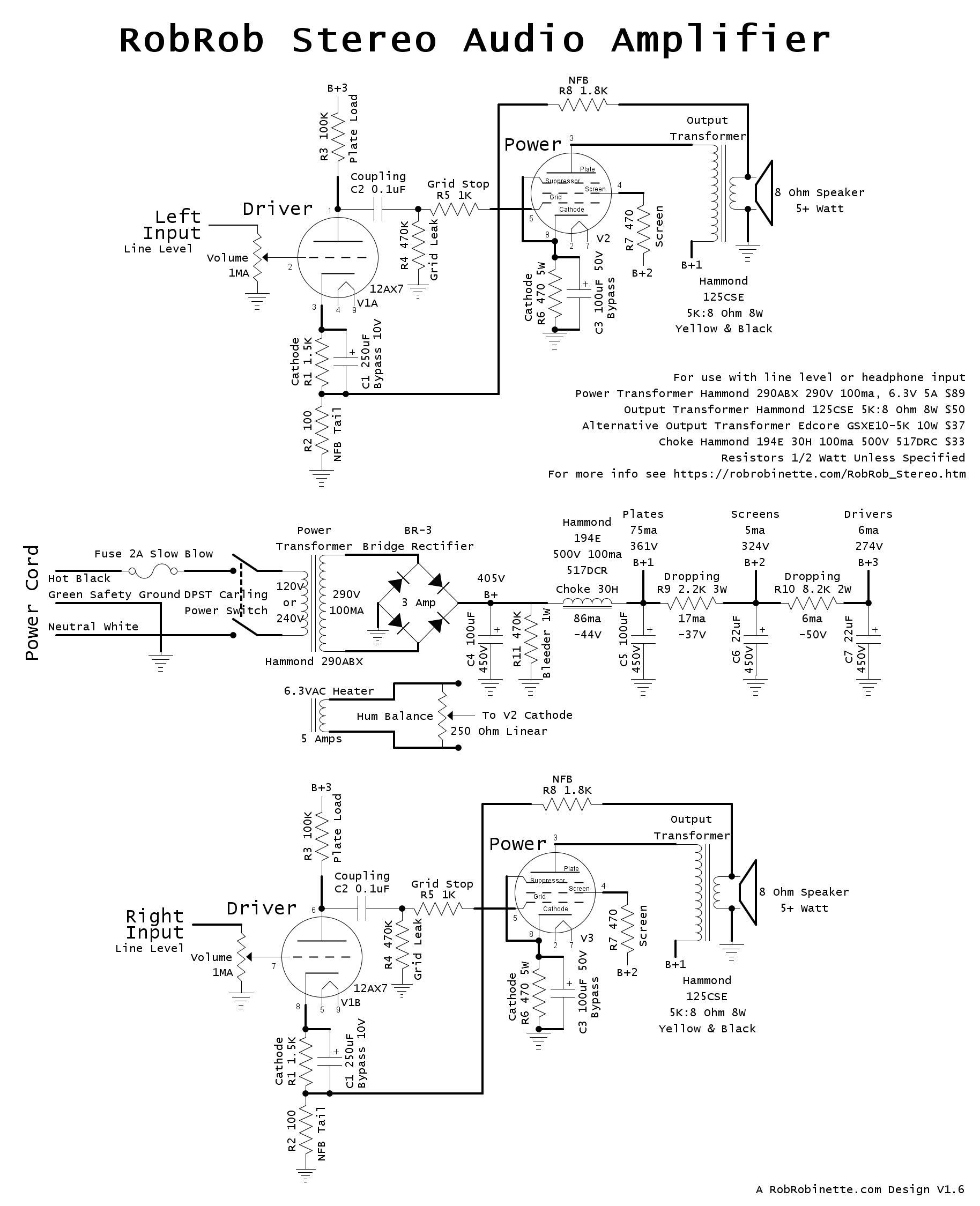
Simple two channel stereo audio amplifier with a common, well filtered power supply. The large 30 Henry choke filters the entire power supply including the power tube plates (B+1). Click on the above image to see the full resolution schematic, download the pdf layout and DIYLC file.
The Hammond 1444-10825 aluminum chassis at 10" x 8" x 2.5" is an easy fit.
Three amp 1000v rated bridge rectifier from Mouser. You can also build the rectifier using two tag strips and four 1N4007 diodes.
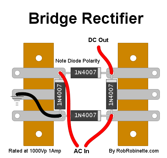
Simple to build 1000 peak volt bridge rectifier using two tag strips and four 1N4007 diodes.
Transformers are all from Hammond:
290ABX power transformer 300V @ 100ma, 6.3v @ 5A (supports 120 & 240v primary) $89. A transformer with a 270 or 280v secondary would also work in this amp.
Optional $28 AnTek AS-05T280 toroidal power transformer 280v 90ma (50VA), 6.3v @ 4 amps. It has a 120v and 240v primary. Another bonus is it only weighs 2 lbs. Size is 3.75" in diameter and 1.6" tall. You can mount the transformer on the top of the chassis and purchase a 105x45mm round transformer cover or leave it exposed.
![]()
Detailed AnTek Wiring
![]()
125CSE output transformer 5K:8 ohm 8 watt $50 (2 each). A nice option if you can wait the 4 to 8 week build time is the Edcore GSXE10-5K output transformer 5K:8 ohm 10 watt $38. The 5 watt Hammond 125BSE or 10 watt 125DSE can also be used. The 5 watt rated 125BSE will compress at high volume levels and the 10 watt 125DSE will yield maximum volume and fidelity.
194E choke 30H 100ma 517 ohm DC resistance $33. Note the choke's 517 ohms of DC resistance was used to drop voltage. If you use a different choke you may need to add a voltage dropping resistor to get the B+1 voltage down to 360 volts or lower.
6-Lug terminal strips are from tubesandmore.com. The second lug is grounded because it is used to bolt the strip to the chassis (second lug marked with ground symbol in the layout below).
I like to use these style dual speaker binding posts:
For the build sequence I recommend you start by drilling the chassis for the IEC socket, power switch, volume pot, input jack, speaker binding posts, bridge rectifier bolt, transformer mount and pass-through holes and tube mount holes. Install the tag strips, tube sockets, power switch, volume pot and bolt down the bridge rectifier directly to the chassis for cooling.
Mount the transformers and choke, add grommets to the transformer and choke pass through holes and feed their wires through to the chassis interior.
Wire the 6.3v heater wires next including the hum balance pot and pilot light. Twist the heater wires and keep them down against the chassis to minimize 60Hz heater hum. Then install the filter caps, other components and wire the rest of the amp.
If you would prefer a tube rectifier you can use an EZ81 and follow the rectifier layout for the Bassman Micro. The EZ81 uses 6.3v heaters so the 290ABX power transformer's lack of a 5v secondary is not a problem.
I recommend following my Amplifier Startup procedure to safely add power for the first time.
If you have problems see my Tube Amp Troubleshooting webpage.
Since this amp uses negative feedback (NFB) there is a 50-50 chance you will get a very loud positive feedback squeal when you first power up this amp. If this happens simply shut down the amp, verify the filter caps have zero voltage (they should since resistor R11 will bleed the caps) and swap the output transformer blue and brown primary wires.
To adjust the hum balance pot you turn the amp up to full volume with nothing plugged in then adjust the pot for minimum hum. If you don't hear a difference then leave the pot in the middle of its travel.
If you would like to use this amp with a pair of headphones you can simply connect two 10 ohm, 10 watt resistors across each pair of speaker out terminals (+ to -). This will show the amp an approximate 8 ohm load when paralleled with the headphone load which can be anything from 8 to 600+ ohms. Then connect a headphone out adapter to the speaker terminals. I have done this with several tube amps and you would be surprised how good it sounds.
If you would prefer to have separate left and right volume controls simply use two 1MA (audio) volume pots and move the left volume pot to the other side on the input jack.
RobRob Stereo Audio Amp Layout
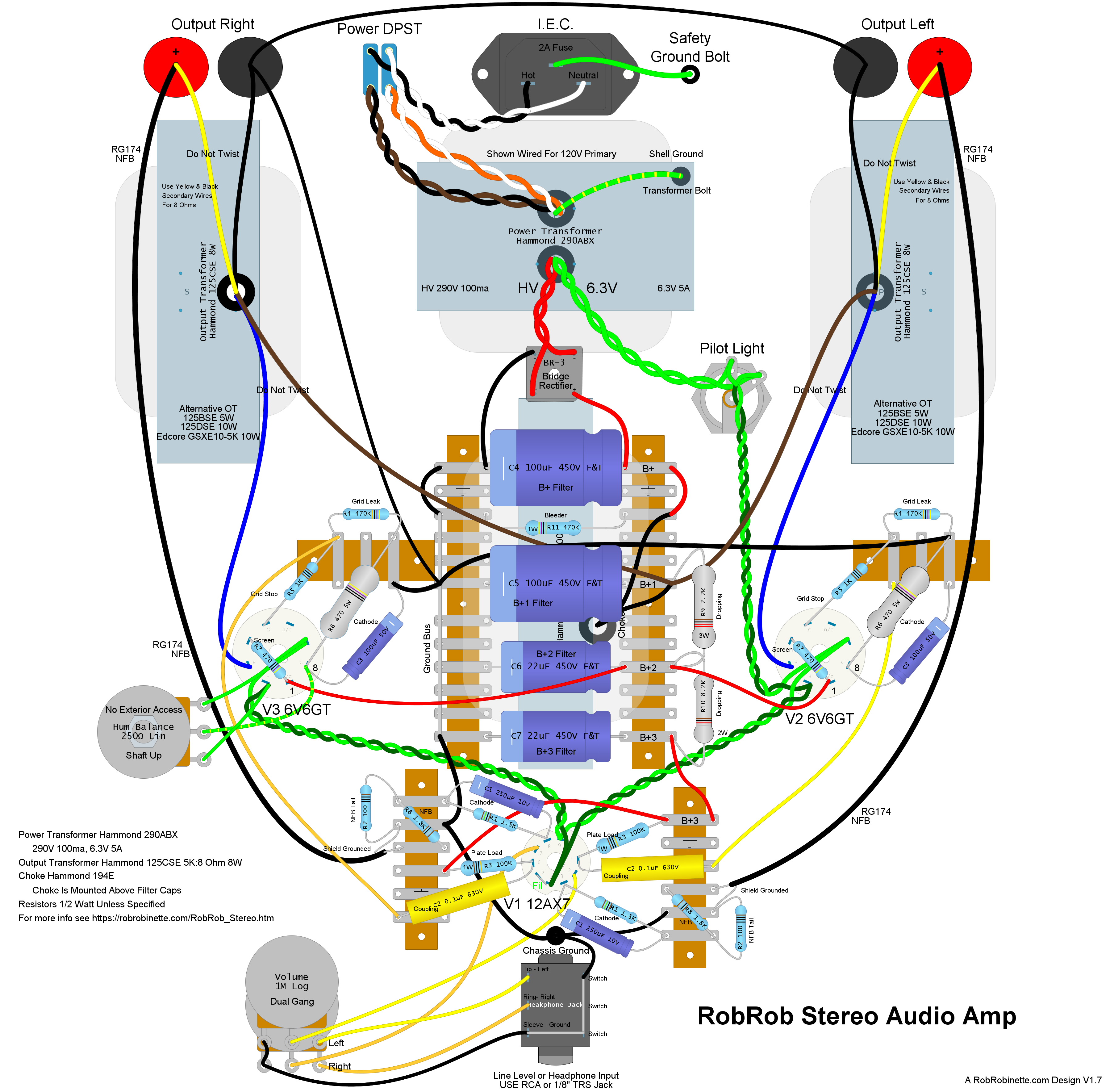
This layout is for a 10" x 8" x 2.5" Hammond 1444-10825 aluminum chassis. View of the amp from the underside of the chassis so left and right are reversed. It's such a simple amp that point-to-point wiring made sense. The three transformers and choke are mounted on top of the chassis so the interior of the chassis will not look quite as chaotic as the layout above. The long terminal strips in the middle are two 6 lug terminal strips joined together. The hum balance pot is mounted inside the chassis and is not accessible from outside the chassis (you don't want people turning that knob willie -nillie). The long NFB runs from the positive speaker posts to V1 need to use shielded cable such as RG174. Ground the cable shield at only the V1 end to prevent a ground loop. Click on the above image to see the full resolution layout, download the pdf layout and DIYLC file.
Bill of Materials
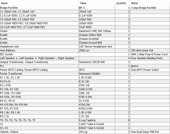
You will also need a chassis.
Left Channel Signal Flow
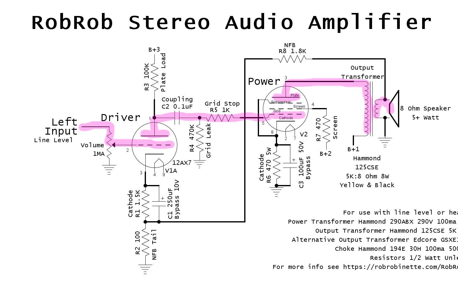
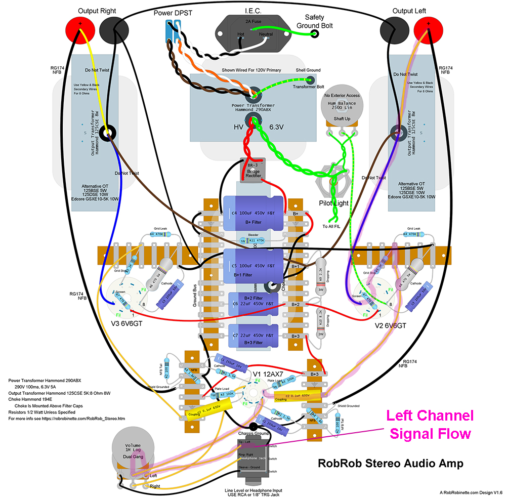
Signal enters at bottom center input jack, flows to the volume control, then the V1A grid, out the plate through the coupling cap up to the V2 grid stop resistor and grid, out the plate to the output transformer primary and then the secondary out to the speaker.
Annotated Harman Kardon A300 Tube Stereo Amp Schematic
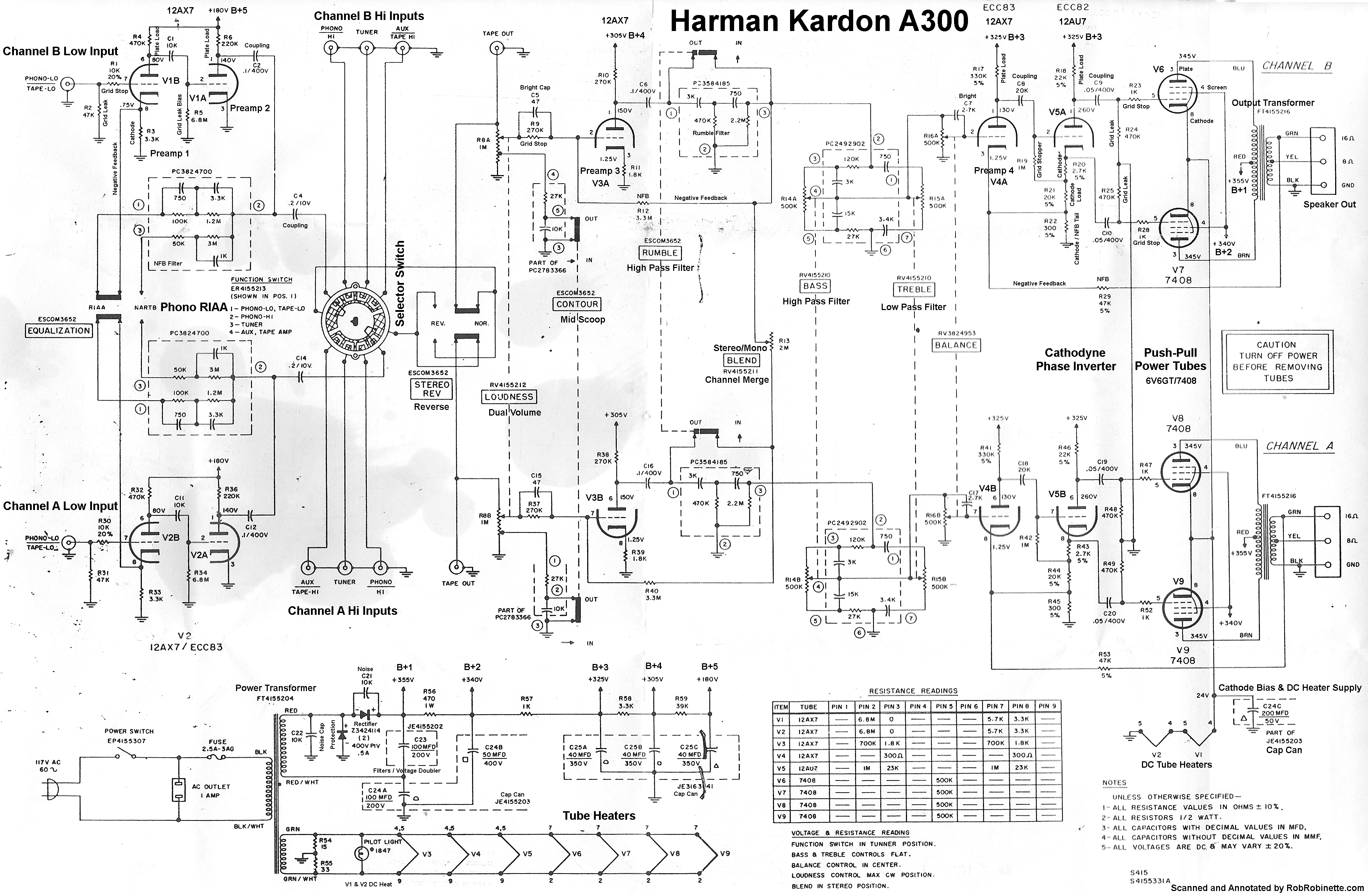
Notice all the tone shaping circuits: RIAA phono equalization, Stereo Reverse, Loudness (volume), Contour (mid scoop), Rumble (low freq filter), Stereo/Mono Blend, Bass, Treble and Balance. The turntable RIAA equalization circuit uses filtered negative feedback. This amp uses no cathode bypass capacitors to take advantage of the local negative feedback generated by cathode resistors. Preamp 2 uses grid leak bias--a large value 6.8M grid leak resistor generates the bias voltage. Global negative feedback from the output transformer is applied to the V4 (Preamp 4) and V5 (phase inverter) cathodes. Negative feedback reduces noise and distortion, flattens response and increases bandwidth. 24 volts of DC are applied to the power tube cathodes for bias. The 24v DC bias voltage is also used for DC heat for V1 and V2 (12 volts each) to minimize preamp heater hum.
A300 Signal Path
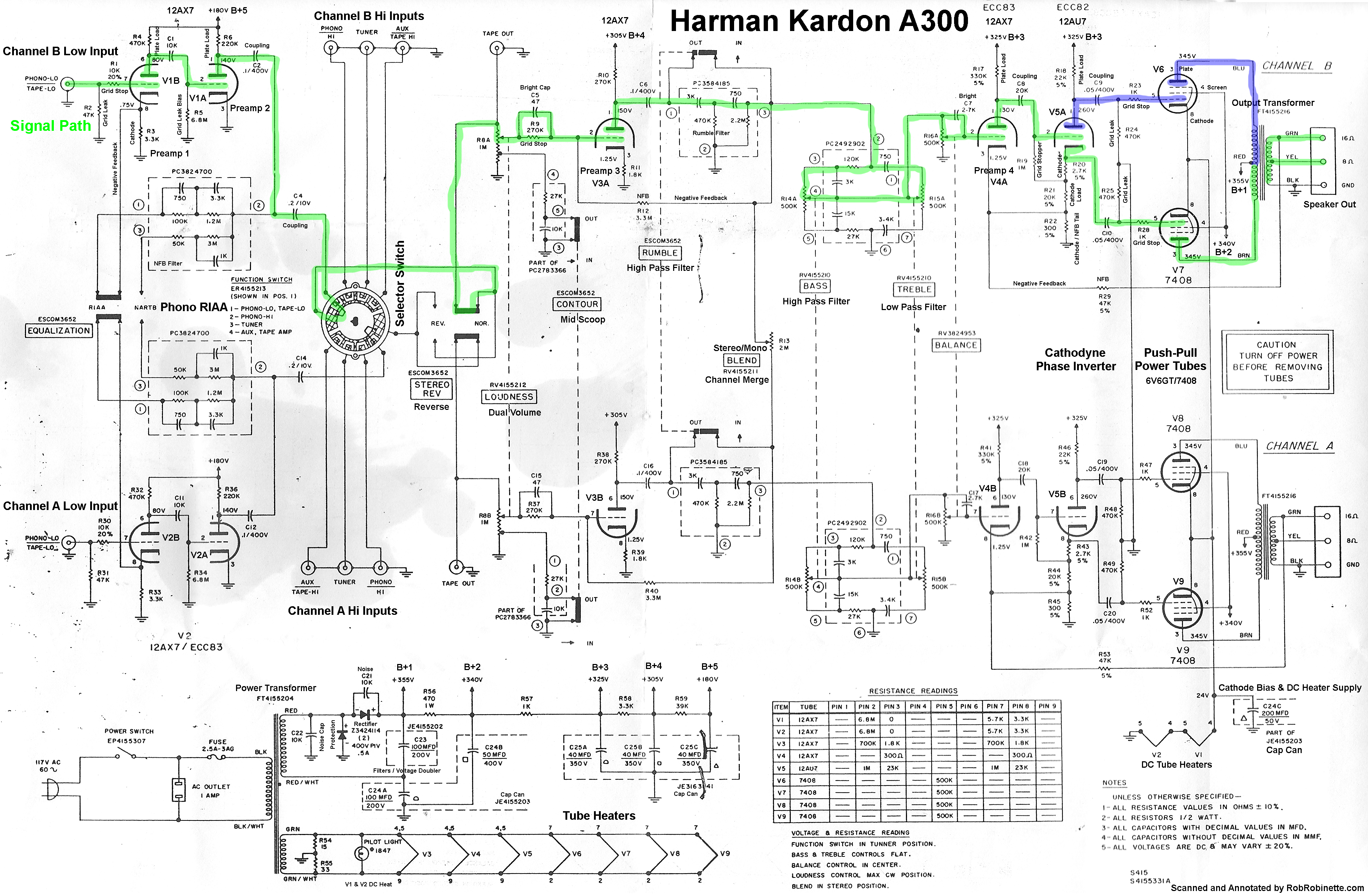
The green highlight shows the signal path through Channel B. The path through Channel A is identical. The signal begins at upper far left at the "Low Phono" input. The inverted signal coming off the cathodyne phase inverter plate is shown in blue.