How To Install SPC Adjustable Ball Joints (Camber Kit) in the S2000
& How To Remove the Brake Rotors
& How To Remove the Brake Dust Shields
By Rob Robinette
I needed more negative camber in the front of the S2000 so I installed these adjustable ball joints (a.k.a. camber kit). While I was at it I removed the brake dust shields which necessitates removal of the brake caliper and rotor. The SPC Honda S2000 adjustable ball joints will give you about plus-or-minus 2 degrees of additional camber adjustment (if you can get -1.5º with the stock adjuster, you can get over -3.5º using this kit). I actually got 2.2º of additional negative camber from my kit. I got my 2 front ball joints from www.iapdirect.com for $165 (front kit only). The Tire Rack sells them for $74 each.
Because the ball pivot is extended to make room for the adjuster these SPC ball joints raise the roll center which is a good thing for a lowered car.
Note: The same SPC ball joint kit, SPC #67220, fits in the front and rear of the S2000, but 17 inch wheels or larger are required for installation in the rear. Since you can usually get about -3º of camber in the rear of the S2000 using the stock adjusters, a camber kit normally isn't needed in the rear.
Warning: The alignment will be out of spec after installing these ball joints, and grossly so if you change the camber. The more camber you add the more toe-out you'll have. You will need an alignment after this install.
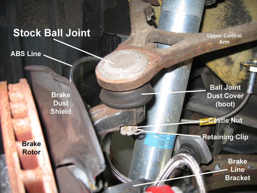
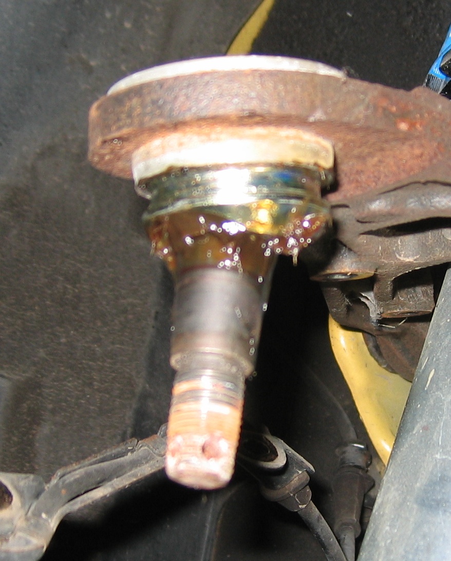
The stock front upper ball joint.
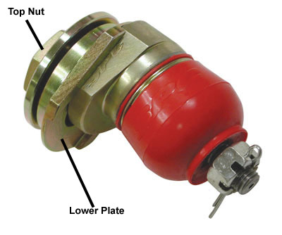
The SPC Adjustable Ball Joint
Special Tools Needed
For the ball joint install you will need a generic ball joint separator or a puller (what I used) and a ball joint press. This $36 OTC 6297 Ball Joint Separator should work to separate the ball joint from the wheel hub.
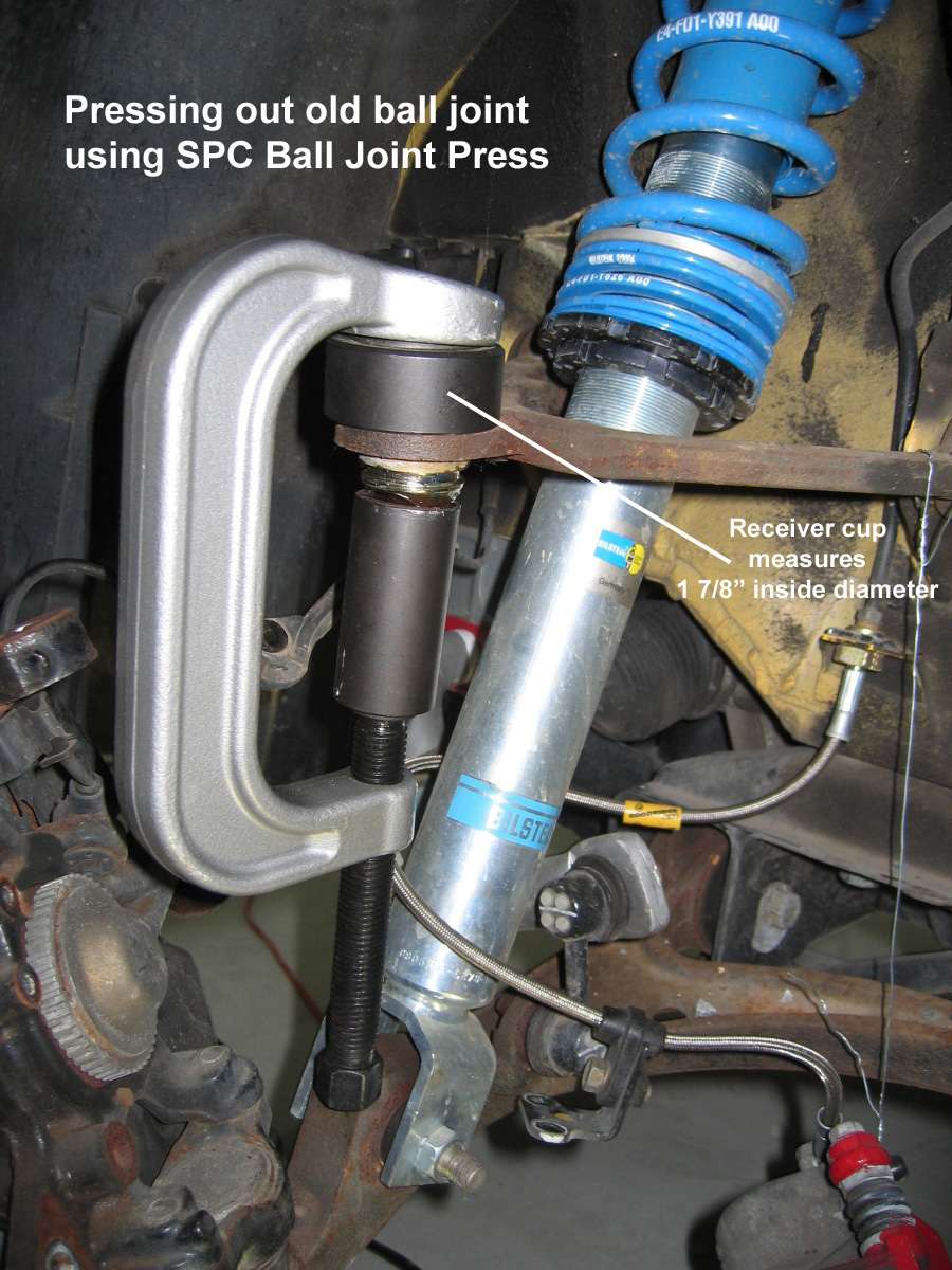
The stock ball joint is press fit into the upper control arm and must be pressed out and the SPC bottom plate must be pressed in. I purchased SPC's #4920 Honda specific ball joint press and used it to press out the old ball joint and press in the bottom plate. The SPC ball joint press's receiver measures at 1 7/8" inside diameter (goes over the top of the stock ball joint for removal). The SPC ball joint press was $114 from Jegs SPC Ball Joint Press.
A generic ball joint press with a 1 7/8" ID reciver cup should work.
To remove the brake disks you may need an impact driver to remove the two Phillips head screws securing them. If the screw is stripped it's very easy to drill out the brake disk screws. They're made of a very soft material so you can remove just the head and not damage the rotor with the right size drill bit.
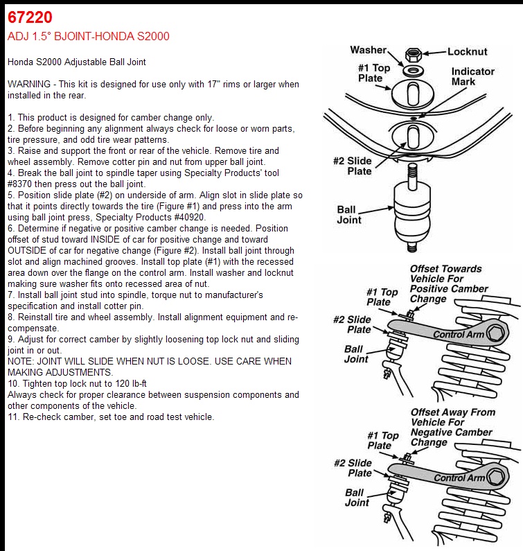
These are the instructions included with the SPC ball joint kit.
Here's SPC's Video of a Honda Civic install. The video shows the use of the SPC Honda Ball Joint Press.
You can install the SPC ball joints without removing the brake caliper or rotor so if that's all you're doing then disregard the info on removing the brake rotor, caliper and dust shields.
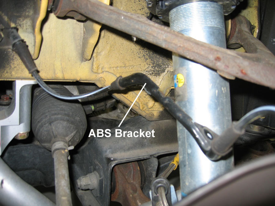
Start by removing the two 10mm bolts holding the ABS Line Bracket in place. This will allow slack in the line so you can move the wheel hub out of the way for the ball joint install.
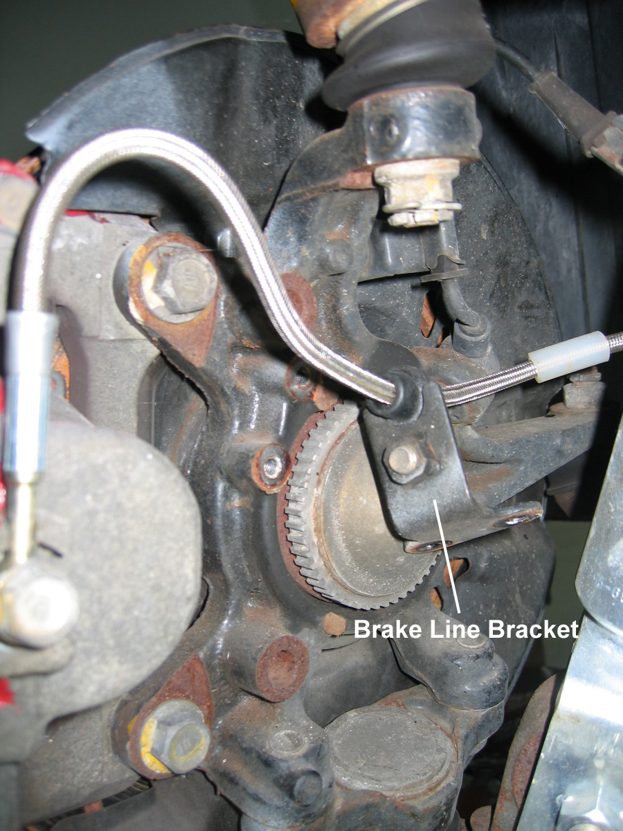
If you're removing the brake caliper, rotor or dust shield then remove the two 10mm bolts securing the brake line bracket so you can move the brake caliper out of the way. You'll also need to use something to support the caliper with once it is unbolted. I used safety wire.
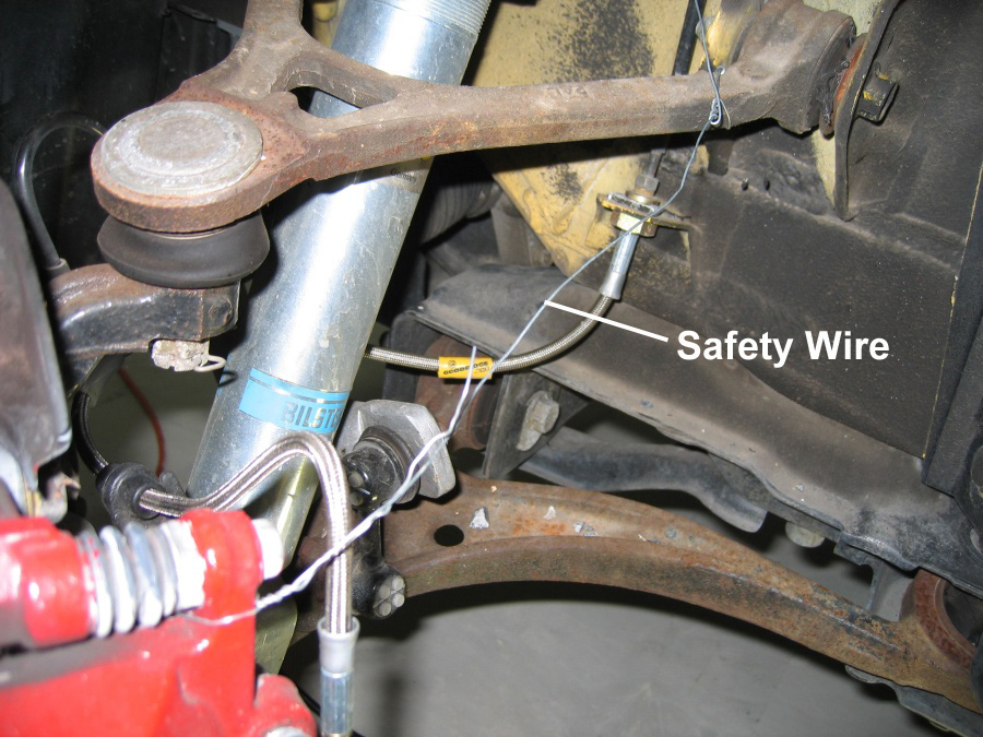
WARNING: DO NOT ALLOW THE CALIPER TO HANG BY THE BRAKE LINE
Here's the safety wire to support the caliper. I attached it to the upper control arm.
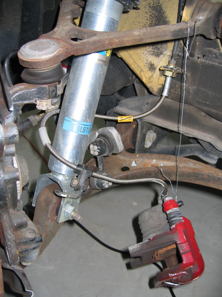
Remove the two 17mm bolts securing the brake caliper, slide the caliper off the rotor, and let it hang by it's support.
Recommended Reading
With the caliper off it's easy to remove the brake rotor and brake dust shield.
Ball Joint Clip
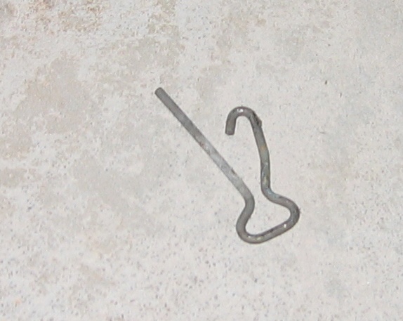
This is the stock Honda clip used to keep the ball joint castle nut in place. Remove it from the castle nut by inserting a thin blade screwdriver into the "hook" to pry it away from the castle nut while pulling it out with needle nose pliers.
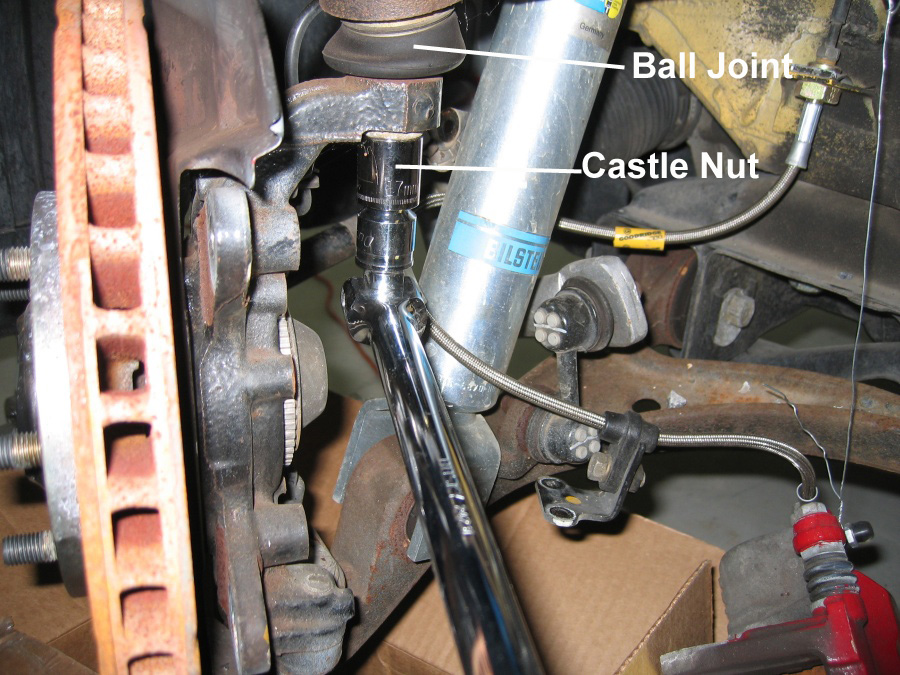
With the castle nut retaining clip out, remove the castle nut. I used a 1/2 inch breaker bar and a 17mm socket.
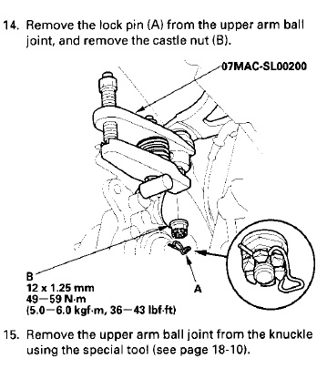
Here's what the S2000 Service Manual shows for ball joint removal.
Be sure and put a nut on the ball joint shaft after you remove the castle nut--it's easy to damage the ball joint to the point of needing replacement if you don't protect the ball joint threads. The primary ball joint threads are 12mm x 1.00 (or possibly 12mm x 1.25, take your castle nut to the hardware store to verify) in size. You can get a hex nut in that size at most hardware stores.
This $80 HarborFreight.com Front End Service Kit works great for separating ball joints from the wheel hub: Front End Service Kit
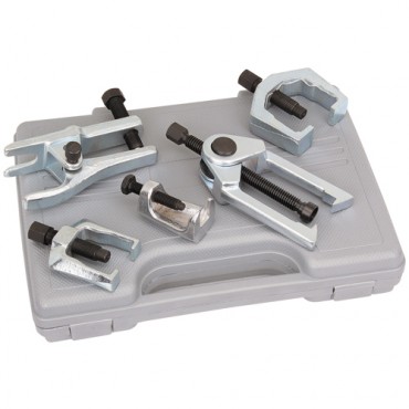
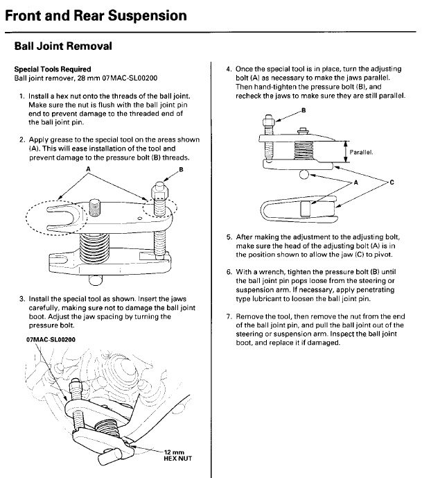
Ball Joint Separator
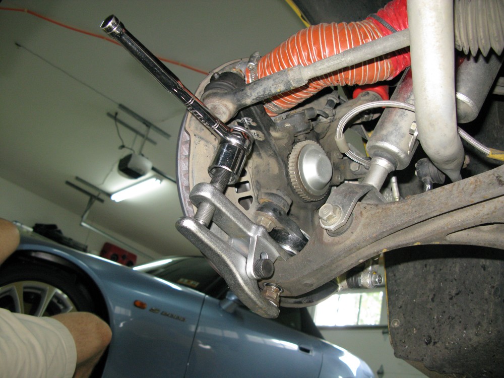
You'll need a ball joint separator to pop the wheel hub loose from the ball joint. Here's the ball joint tool on the front lower ball joint. Notice the castle nut has been reversed and reinstalled to protect the ball joint shaft threads. Jay Balducci wrote and said he damaged his OEM castle nuts when popping the ball joints so he suggest using a std M12x1.25 nut threaded onto each of the ball joints and have the nut fairly flush with the end of the ball joint. The nut will protect the ball joint's threads.
The ball joint is disconnected and the wheel hub is swung out of the way.
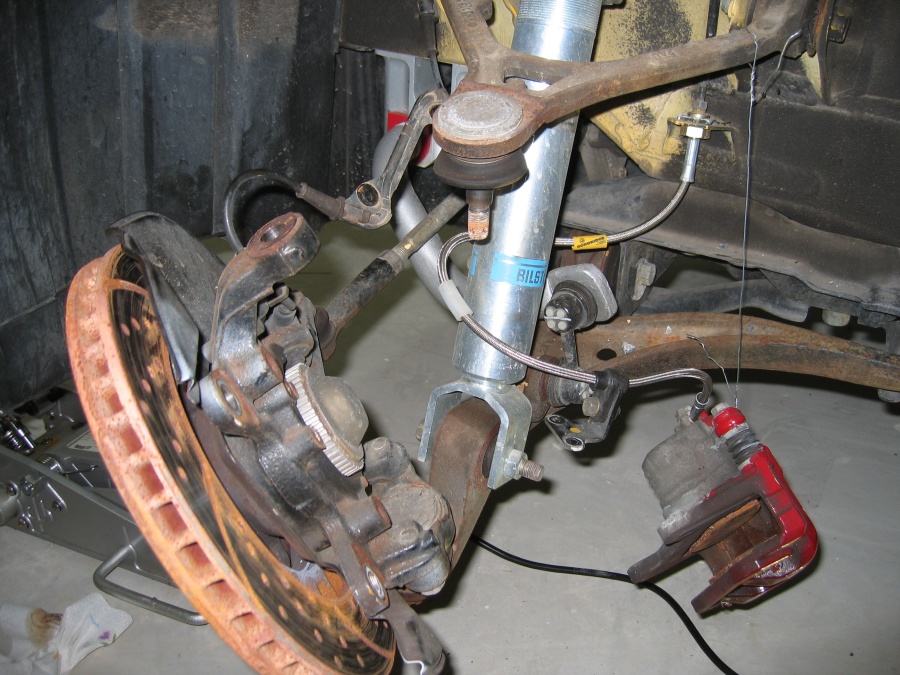
Note there's plenty of slack in the ABS sensor line.
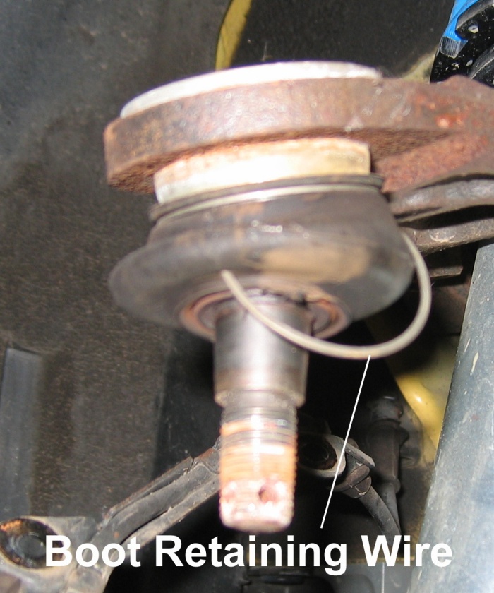
Remove the ball joint boot retaining wire by forcing a thin blade screwdriver under it and pulling it out a little. Use some pliers to pull it completely off. Once it's off it is easy to pull the rubber boot off.
Here's the bootless ball joint ready to be pressed out of the upper control arm.
If you don't want to damage the stock ball joints then put the stock castle nut back on the ball joint spindle upside down (castle lugs pointing up) and flush with the end of the spindle to prevent the spindle thread from being damaged by the ball joint press. I didn't do this because I discarded the stock ball joints after removal.
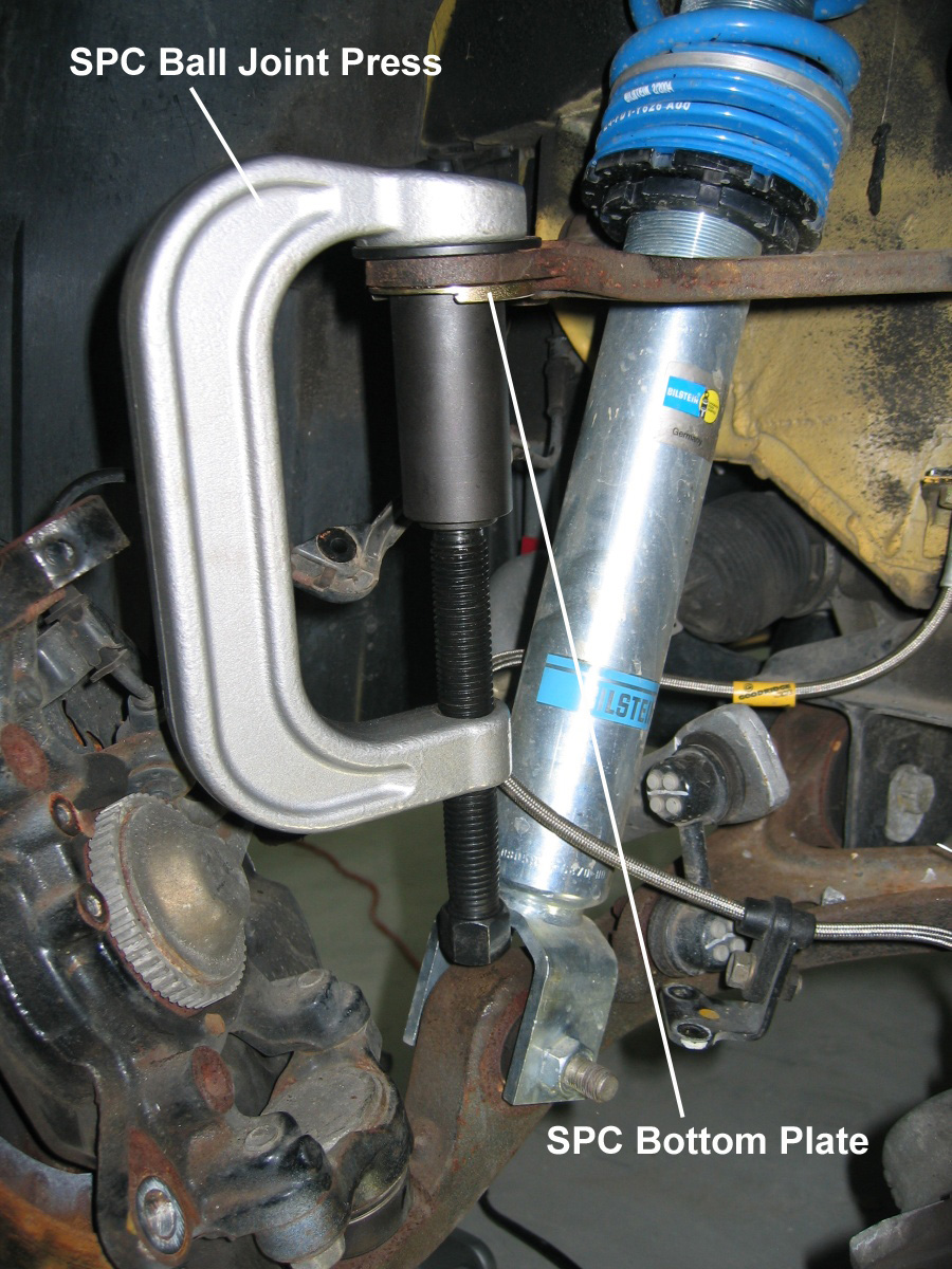
SPC #4920 Honda specific ball joint tool
I purchased the SPC #4920 Honda specific ball joint tool and used it to press out the old ball joint and press in the SPC ball joint bottom plate, but a less expensive generic ball joint press may work too. The SPC tool was $114 from Jegs SPC Ball Joint Press.
Pressing in the SPC bottom plate is the hardest part of this procedure. The slot that allows the camber adjustment needs to be as perpendicular to the car's longitudinal axis as possible, in other words the slot needs to be oriented directly away from the car. The more accurate you are with this the less the caster will change when you adjust the camber. The difficult part is you cannot see the slot when the press is in place and it's difficult to keep the bottom plate from moving around while you work the press into place. I used the trial-and-error method. I pressed the plate in just enough to hold it in the control arm then removed the press to confirm the slot alignment. I had to press it out twice and try again to finally get it right.
If you can't get the slot alignment perfect, it's better to have the slot angling toward the inside rear of the car because if it angles to the inside front your caster will be reduced (not good) when you add negative camber.
By intentionally angling the bottom plate slot toward the inside rear of the car you can add caster along with camber. I angled my slots about 40º to the rear and run 7º of caster and -3.5º of camber. I didn't set the maximum available negative camber, I could have set more than -3.5º.
Once the slot alignment is right, fully press the bottom plate into the upper control arm.
Here's the SPC bottom plate pressed into place.
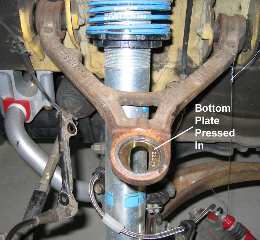
After this photo was taken I angled the slot 40º to the rear to add caster and camber when sliding the ball joint inward.
The SPC ball joint top bolt is offset.
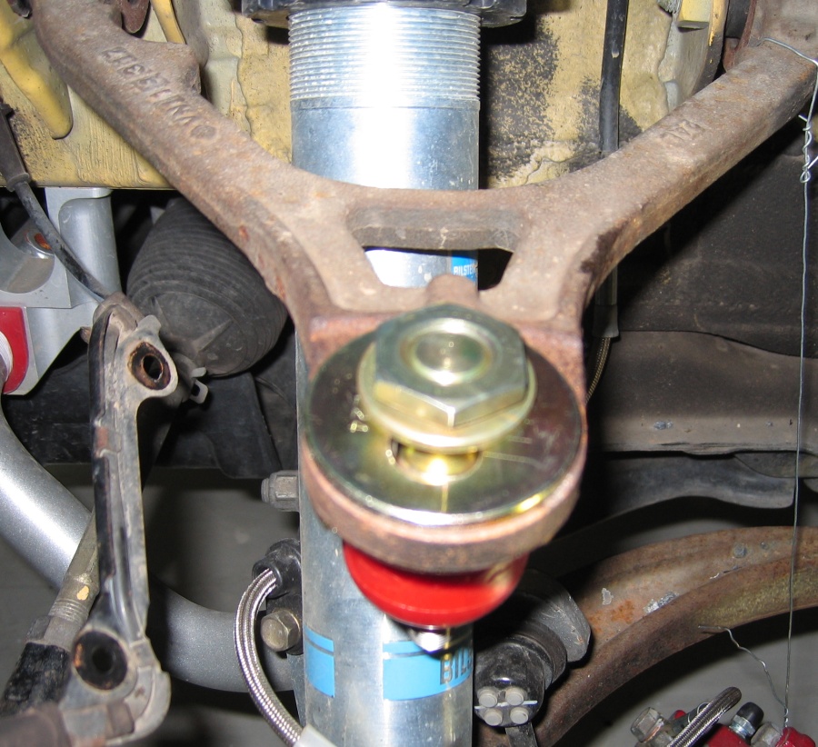
To add negative camber you want the bolt offset toward you coming up through the plates. This big nut needs 120 lb-ft. The ball joint is shown set for maximum negative camber--slid full in.
I had to grind off some material from the ball joint to allow the ball joint to slide fully inward for maximum negative camber. Put the ball joint up through the slot in the newly pressed in bottom plate with the bolt offset toward you. Slide the ball joint fully inward and look to see where the ball joint contacts the upper control arm and you'll see what is keeping the ball joint from moving fully inward. Carefully remove a little material from the ball joint until the ball joint moves fully inward.
Place the top plate (with index marks up), washer and nut (beveled edge down) on and make sure the ball joint slides in and out. Pulling the ball joint fully toward you will give you pretty much the same camber you had with the stock ball joints, push the ball joint toward the car to increase camber.
I recommend you set the ball joints to the full out position (close to stock) and take the car to the alignment shop and have the shop start with setting the ball joints to your initial setting. When you adjust the ball joints for additional camber you will add a huge amount of toe-out. My car's alignment specs went from -1º camber and 0º toe before the install, to -3.2º camber and -1.48 total toe-out! So unless you have a very short drive to the alignment shop (like I did), don't add the negative camber using the SPC ball joints until you get to the shop.
Set the ball joints to your initial setting and snug down the big top nut (don't torque it yet).
Put the ball joint spindle through the hub's upper control arm hole and secure with the new SPC castle nut. Torque it to 36-43 lb-ft and install the supplied cotter pin.
Torque the SPC ball joint top nut to 120 lb-ft, remember this number because your alignment shop will need to know it. The top nut is pretty thin so be careful not to round off the edges when torqueing it down.
Warning: The alignment will be out of spec after installing these ball joints, and grossly so if you change the camber. The more camber you add the more toe-out you'll have. You WILL need an alignment after this install.
My Initial Setup
I set the ball joints for maximum negative camber (fully inward) and drove the car one mile to the alignment shop. I had the shop do the rear alignment first. I had them set the maximum equal rear camber they could get (up to -3.5º) and ended up with -3.0º camber on each side and the stock toe-in of 0.25" total.
In the front I had them set the maximum equal caster first and ended up with 6.7º. I wanted the front camber to be set a half a degree less than what was set in the rear. Since the rear camber was set to -3.0º, the shop set -2.5º each side in the front. The shop didn't try to set maximum camber so I don't know how much I could have gotten, but they could have set at least -3.2º. Finally the shop set 0º for the front toe.
This is a pretty aggressive track oriented setup. Consult your tire manufacturer's recommended camber settings. The Michelin Sport Pilot Cup R compound tires recommend 1.5º to 3º of negative camber with a max of 4º.
Update November 2011: I'm currently running Front: 7º caster, -3.5º camber, 0 toe; Rear: -3.0º camber 0.25 inch total toe-in.
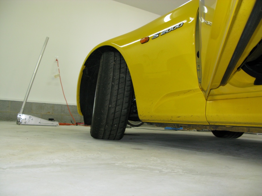
Full lock with 6.7º caster and -2.8º camber
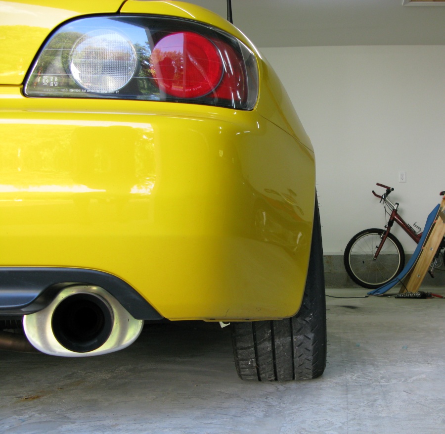
-3.3º camber in the rear from the stock adjusters
If you're not removing the brake rotors or dust shields skip down to Reassembly.
Removing the Brake Rotors
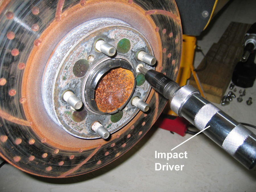
With the caliper out of the way and supported by wire or a bungee, it's usually easy to remove the rotors. You may need to use an impact driver (pictured below) to get the two Phillips head screws out. I had one seized screw that the impact driver couldn't even remove so I used a drill with a 5/16" bit to drill out the head of the screw. The screws are surprisingly soft and drilled out very easily. If you have to do this only drill out as much of the screw head as required to get the rotor lose. You want enough of the screw left so that when you remove the rotor you can grip what's left of the screw with vice grips to remove it. To prevent these screws from seizing up, put some anti-seize on both the threads and the the tapered part of the screw head before re-installing them and only torque them to a gentle 7.2 lb-ft.
Using an impact driver to remove the 2 brake rotor Phillips head screws.
With the 2 Phillips head screws removed you can usually get the rotor lose by simply striking the back side of the rotor with the palm of your gloved hand. If that doesn't work the shop manual shows using 2 8x1.25 bolts inserted into the two empty (non-countersunk) holes in the rotor. Insert them and turn them both to push the rotor away from the hub. A rubber mallet to the back side of the rotor works too.
Removing the Brake Dust Shields
Before you do this make sure you won't want to add brake ducts to vent your brakes in the future. I vented my front brakes after I removed my dust shields and ended up having to buy new ones and install them so I would have a place to secure the vent air hose. You can see the brake duct How-To here.
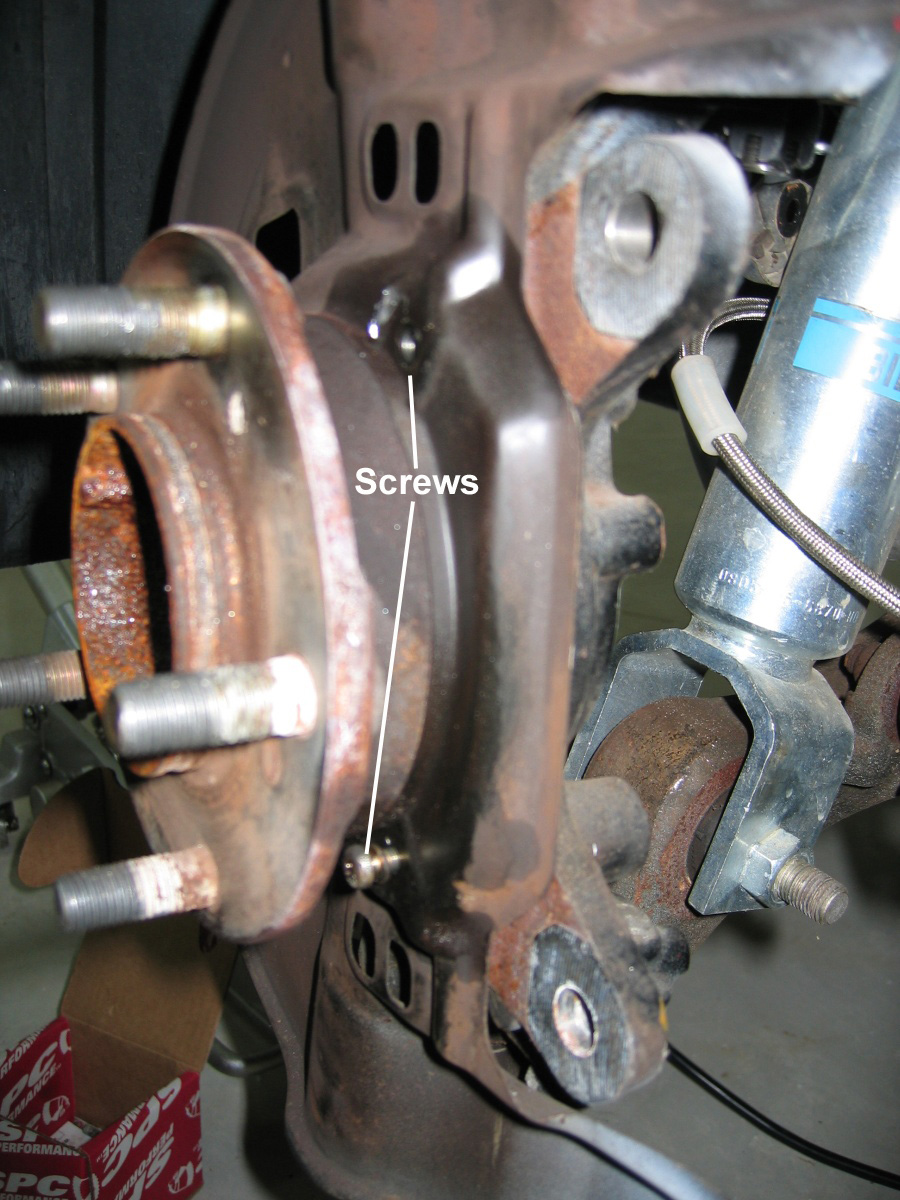
To remove the dust shields you must remove the brake caliper and rotor as shown above. With the rotor off you will see 3 Phillips head screws. As soon as you have access to the screws squirt them down with some Liquid Wrench or other penetrating lube. Let the lube soak in for a while.
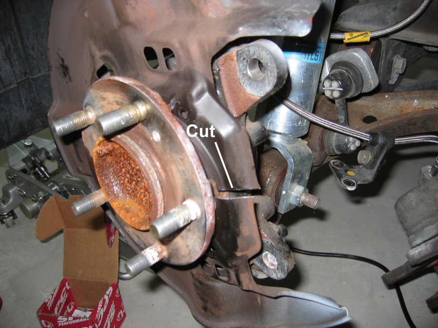
The official way to do this job is to separate the hub from the knuckle, but it can be done much more easily by simply cutting the dust shield off. They are inexpensive if you ever want to re-install them.
Three screws hold the dust shield in place (one is on the back side out of view).
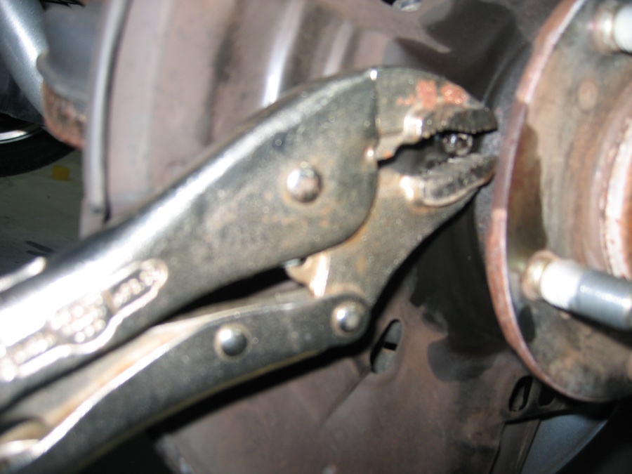
Use vice grips to grab the screw head and loosen them.
Use tin snips to cut the dust shield as shown, then bend them (with gloved hands) to remove.