[ How the 5E3 Deluxe Works ] [ Deluxe Models ] [ DRRI & 68 CDR Mods ] [ My 5E3 Build ] [ Spice Analysis ] [ The Trainwreck Pages ] [ Fender Input Jacks ] [ B9A Prototype Boards ]
VHT Special 6 Ultra Guitar Amp Mods
By Rob Robinette
Add a switched power tube bias, switched variable negative feedback, treble, mid & bass controls, convert the Boost Switch into a Raw Switch, BitMo Reverb kit, internal 8 inch speaker, internal speaker jack, Master Volume, effects loop send & return level controls, choke, 9 volt effects pedal power, reduce Boost Volume change, Distortion/Overdrive switch and the Kleuck "Tweed" mod.

The VHT Special 6 Ultra is an amazingly flexible 6 watt tube guitar amp. It's a single-ended, class A amp using a single power tube (6V6 or 6L6, EL34, 6CA7) and features a hand wired eyelet circuit board with easy to reach components for easy modification. The Ultra has almost all of the mods I would have done to the non-Ultra Special 6 amp. The Ultra even uses a quiet 6.3v DC filament heater circuit for both preamp tubes.
The Ultra amp head costs less than $400. You can get a combo version for about $60 more that has the exact same chassis but comes in a cab with a 10 inch VHT Chromeback speaker which gets very good reviews. The Special 6 Ultra is jam packed with features and is an amazing value. You can find more info about this amp here: VHT Special 6 Ultra
If you can live with less features the VHT Special 6 Head (non-Ultra version) sells for around $200 and comes with just the Clean channel and a volume and tone control. The Special 6 Combo with 10" Chromeback speaker is only $20 more. You could not build one of these yourself for that kind of money so they make a great amp to learn amp modification.
One note about using the Ultra, the amount of control offered with all the sound shaping knobs can be overwhelming. I recommend you take notes when playing with this amp because many of the controls interact and it can be difficult to get back to that "fantastic tone I had the other night." Add in tube rolling and the options are freakin' infinite.
WARNING: A tube amplifier chassis contains lethal high voltage even when unplugged--sometimes over 700 volts AC and 500 volts DC. If you have not been trained to work with high voltage then have an amp technician service your amp. Never touch the amplifier chassis with one hand while probing with the other hand because a lethal shock can run between your arms through your heart. Use just one hand when working on a powered amp. See more tube amplifier safety info here.
The Ultra channel input jack acts like a tube overdrive pedal. It uses one half of tube V1 (V1A) to amplify the guitar signal before it is passed directly to the Clean channel input jack which then uses V1B as it's preamplifier. In other words the Ultra channel is cascaded into the clean channel for an extra gain stage.
I recommend you start with the rotary Depth switch which is a super cool "mod" VHT put on the SP6 Ultra. It can really change the overall flavor of the amp so don't "set it and forget it." The Depth switch is designed to help match your guitar's pickups to the amp. The Depth switch changes the value of the power tube cathode bypass capacitor. Turning the knob clockwise will extend the bass depth. It allows you to dial the power tube bypass capacitor from a really tiny .22uF all the way up to a Fender tweed style 22uF. A really small bypass cap will boost only high freqs so it's a way to dial out some "boom" from bass heavy humbucker pickups. For your single coils and vintage Tele dial the depth control up to it's max to get some meat with your vintage tone (vintage amps had larger bypass caps). If you overdrive the amp hard with the Ultra channel or pedals try dialing down the bypass cap to tighten up the overdrive tone. The harder you overdrive the amp the smaller the bypass cap should be.
You can go from Fender to Vox to Marshall using the Depth switch in combination with the Texture switch. The Texture switch rolls off some high end by filtering the output transformer secondary (speaker output). The mid position lets all the highs through to the speaker. Use the Texture switch to eliminate ice pick highs or tame the high end of a really bright guitar pickup. Another benefit of the Texture switch is it allows you to vary the post clipping EQ of the amp while the tone control allows pre-clipping EQ. You should use both tone controls to fine tune your overdrive tone.
In the Standby switch's 'High Power' setting the power tube is in its normal pentode mode with its plate at B+1 and screen grid at B+2 DC voltage. In 'Low Power' the power tube runs in the triode mode with its plate and screen grid tied together at B+1 voltage. The power tube overdrive tone is very different in the low power triode mode so be sure and sample it.
The 'Watts' control is a variable voltage regulator (VVR) used for power scaling. The Watts control reduces the voltage to the power tube's plate (B+1) and screen grid (B+2). You can push the amp into heavy power tube overdrive and yet turn down the Watts control and reduce volume without effecting the tone and amp playing dynamics too much. All VVR's sound mediocre when you really crank the volume down.
Even though the amp sounds great with the stock Chinese tubes the first thing I did was replace the factory tubes with two Tung-Sol Reissue 12AX7's and a new old stock (NOS) GE 6V6GT. People seem to really like the JJ 6V6 too. You can double the output of this amp by adding an output tube bias resistor (described below), installing an EL34 or 6CA7 power tube and connecting an 8 ohm speaker with 16 ohm impedance selected (or 4 ohm speaker & 8 ohm selected).

This amp sounds fantastic but I bought it to mod it and learn tube amp theory. By opening up this amp and playing with it's insides I have gone from having a mediocre understanding of electronics and no clue how tubes work to being comfortable reading schematics and understanding the function of every component in the amp. This amp also inspired me to build my own Fender 5E3 tweed Deluxe clone and 5F6-A tweed Bassman and design the Bassman Micro, Deluxe Micro and Champ Micro amplifiers. So here's what I've done to this amp:
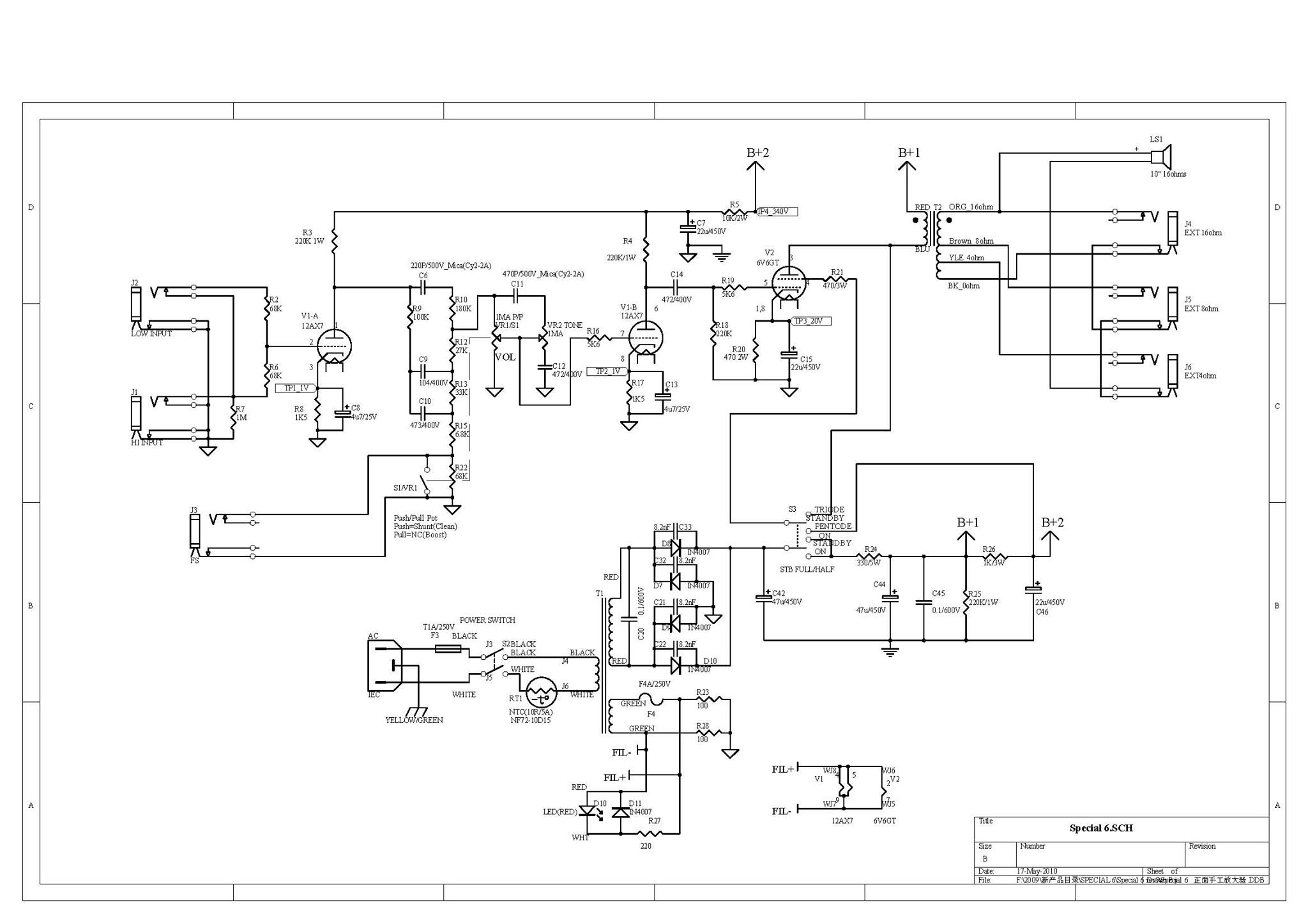
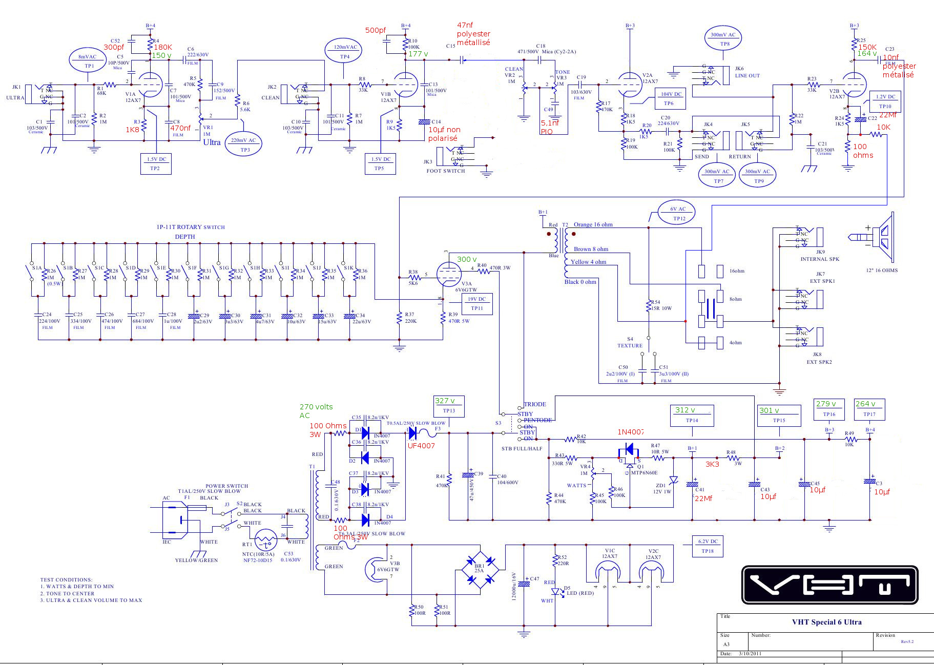
Special 6 Ultra Schematic
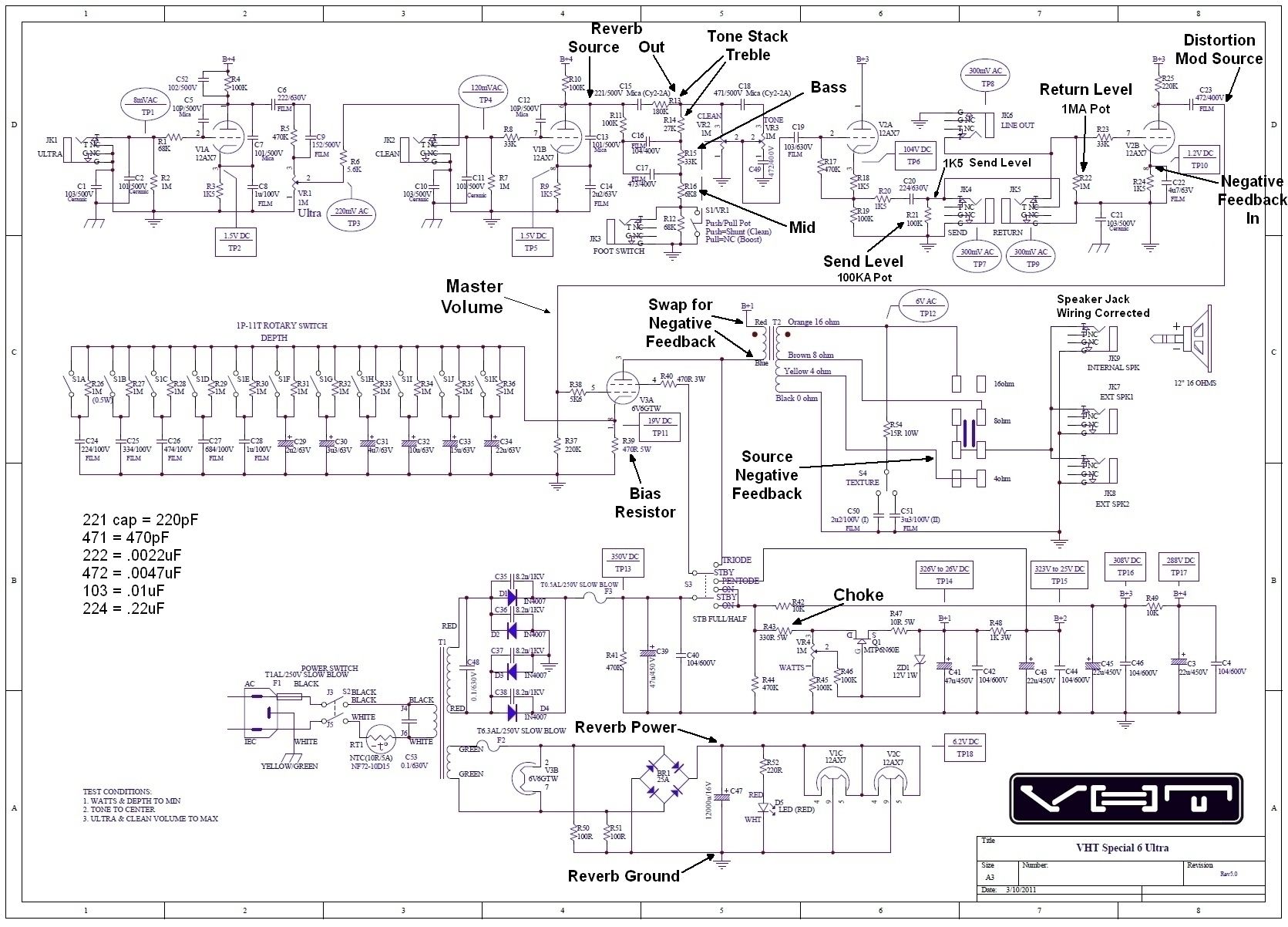
(click schematic for full size image)
Schematic With Block Functions
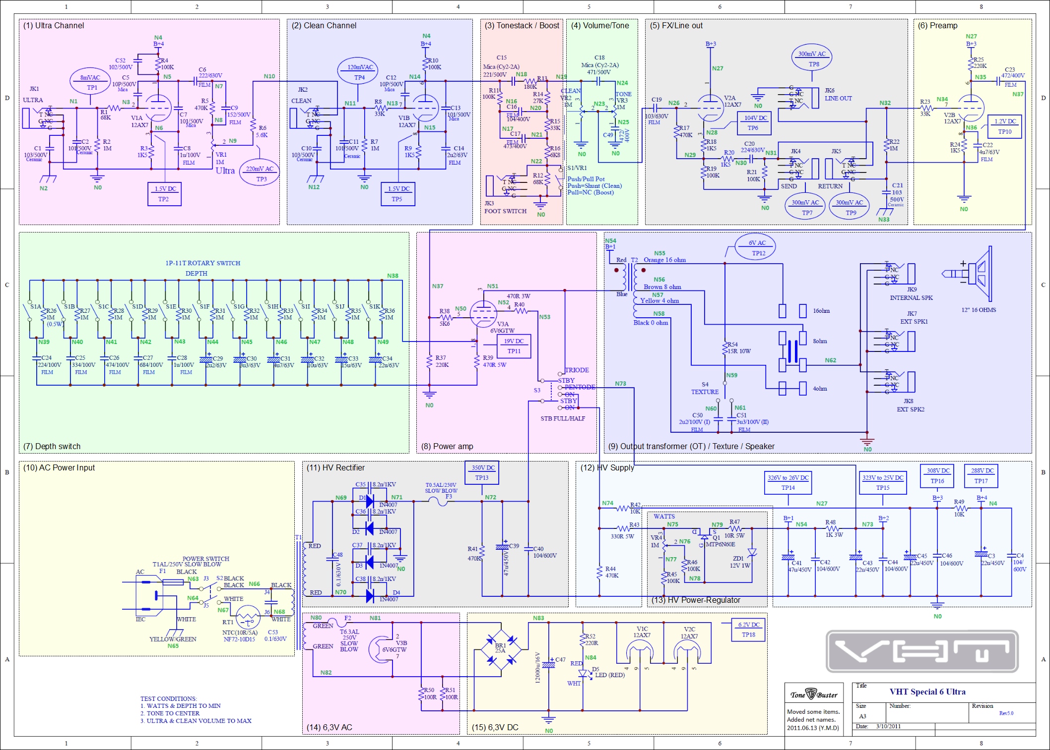
(click schematic for full size image)
When swapping the pre-amp tubes keep in mind both tubes do double duty--one half does one thing the other half of the tube does something else:
Tube V1A is the Ultra pre-amp.
V1B (other half of Tube V1) is the Clean Channel pre-amp
Tube V2A is the effects loop buffer (unity gain pre-amp that helps isolate the amplifier from the effects circuits and offers better impedance matching)
V2B is the output stage driver
Tube V3 is the power tube
WARNING
Amplifiers have large capacitors that store enough electricity to kill (or at least scare the piss out of you). You MUST verify no voltage remains in the big filter capacitors before disassembling the amp. The Special 6 Ultra has "bleeding resistors" so you can drain the caps by turning the amp off with the amp's Standby Switch in any position (very nice design touch VHT). Once the chassis is removed verify there is no voltage present by testing the large caps with a multi-meter in the DC volts mode. Put the meter's two probes on both ends of each cap and verify no voltage is read. Also keep in mind the 3 tubes can be very hot.
Start by removing the back panel. There are 9 Phillips head screws in the panel. Remove the 6 screws shown below to remove the amp chassis--be careful, it's heavy.
6 Screws to Remove Chassis
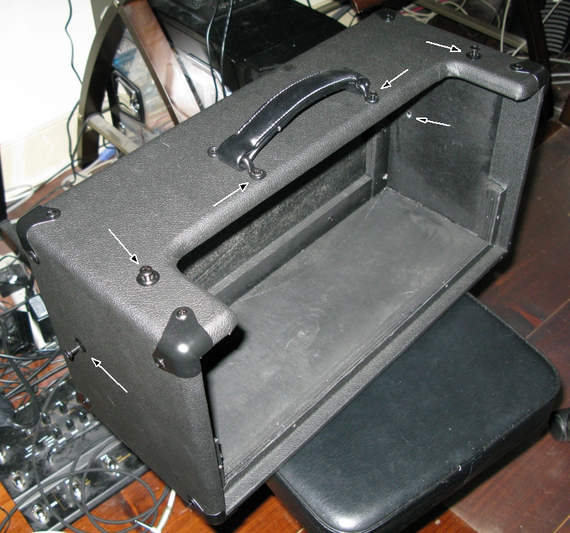
I recommend leaving one of the handle screws as last, then turn the cab on its side and make sure you have a good grip on the chassis as you remove the last handle screw--it's heavy and you don't want to let it drop out of the cab.
Chassis Removed
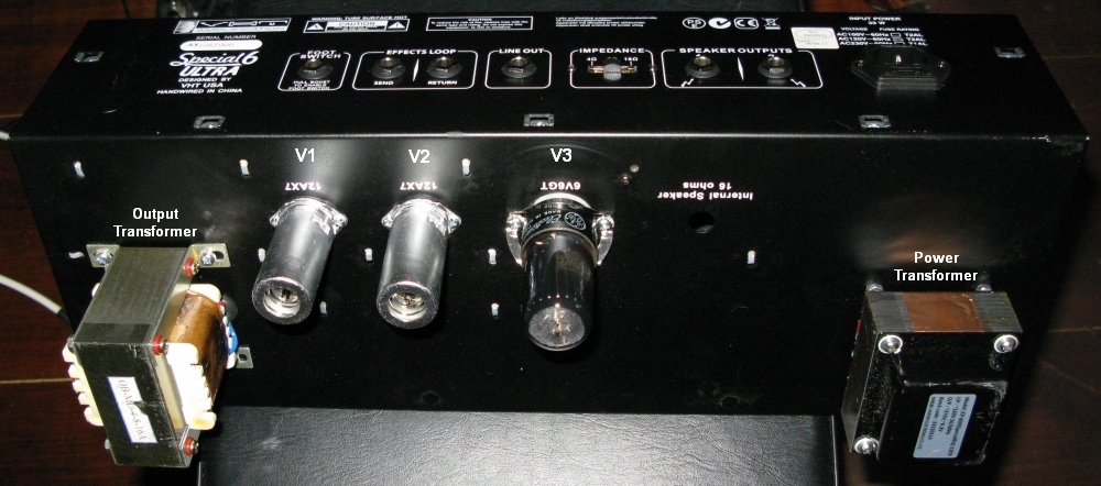
From left to right: Output Transformer, V1, V2, V3, Power Transformer
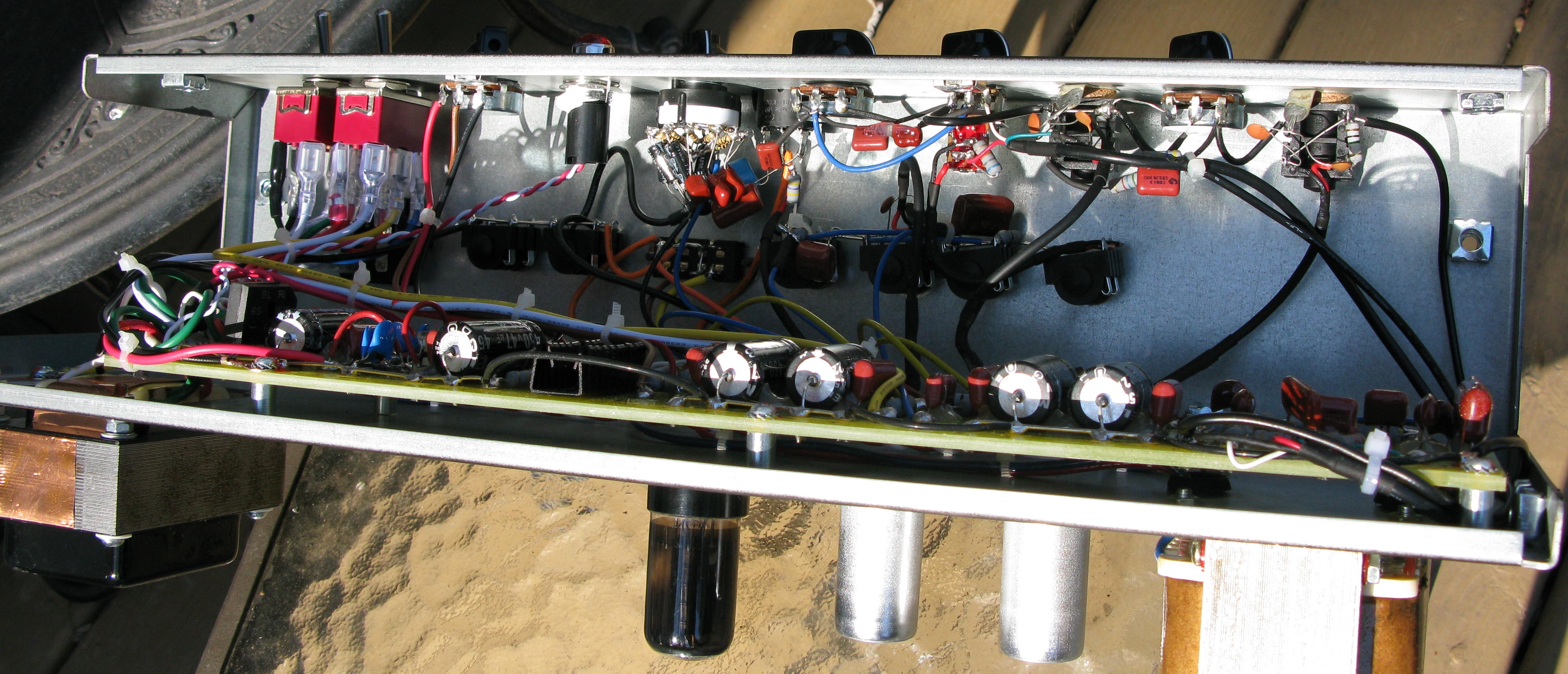
Hand Wired Using Eyelets and Easy Access for Modifications
Click on images for very large detailed versions, circuit board V 1.8 before modification
Circuit Board

VHT Wire Color Code
In General: Red is power--both AC and DC, Yellow is DC, Blue is signal, Black is ground.
Power Transformer: Input wires are 125v AC, Black is hot, White is neutral, Green/Yellow is chassis safety ground. Output wires are high voltage AC through 2 red wires (both hot), 6.2v AC through 2 green wires (both hot).
Output Transformer: Blue is signal in from V3, Red is 326v AC input from B+1, Orange is 16 ohm speaker output, Brown 8 ohm, Yellow 4 ohm.
Tube Filament Heaters: Tightly twisted wire pairs: V1, V2 (pre-amp tubes) and the red "On LED" get 6.3v DC from Red (hot) & White (ground) wires. Using DC for the preamp tube heaters helps cut down on 60Hz heater hum--this is a cool feature. V3 (Power tube) gets 6.3v AC from two White wires (both hot).
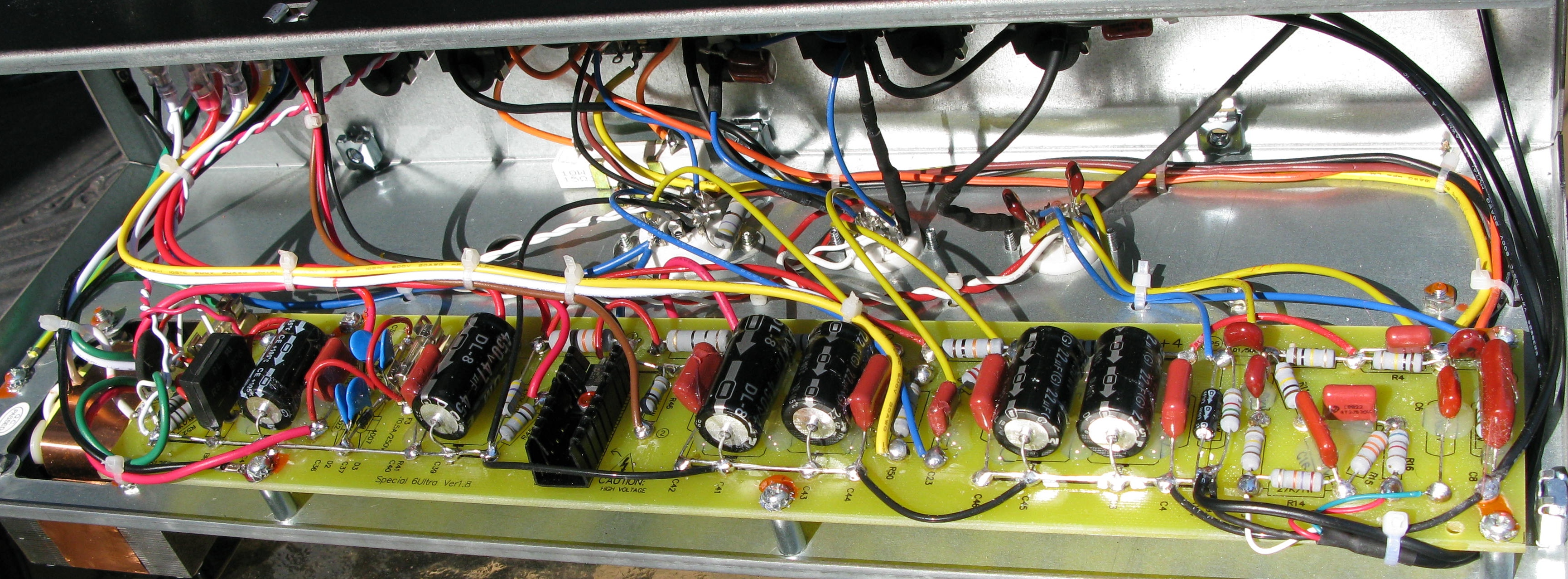
Inside Back Panel
Tube Sockets
Kleuck Switched Power Tube Bias Mod
I learned most of what I know about this amp from the tdpri.com VHT Special 6 (non-Ultra) Mod thread. In that thread kleuck shared a huge amount of knowledge of how to mod the Special 6. He was the first to describe this power tube bias mod.
This is an excellent first mod because it adds the ability to run higher power 6L6, EL34 and 6CA7 power tubes and maximize the amp's power output by adjusting the power tube bias. By putting this extra resistor on a switch you can easily switch between the standard 6V6 tube for practice and high power tubes for gigs. The actual measured output of the (non-Ultra) Special 6 amp was 4 watts clean RMS with a 6V6, and 7 watts with a 6L6. Output for the EL34 and 6CA7 with the bias switch was measured at 8.4 watts.
To add this flexibility you simply add a switched 560 ohm 5 watt resistor (see update below) in parallel with the existing 470 ohm R39 (see pic below). With both resistors connected in parallel bias resistance drops to 255 ohms.
UPDATE Oct 2018: Kleuck contacted me and now recommends a 470 ohm 5 watt resistor to parallel with the existing 470 ohm R39 for a total parallel resistance of 235 ohms. This warms the bias and runs all the big bottle tubes, but especially the 30 watt rated 6L6GC, closer to their operating sweet spot.
Switched Bias Mod
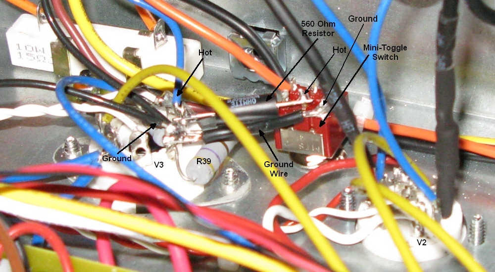
R39 bias resistor is on the V3 (power tube) socket. Near side of R39 is ground, far side is hot. 560 Ohm resistor is soldered to hot side of R39 and toggle switch mid terminal. Ground wire is connected to R39 ground side to toggle switch corner terminal. It would be preferred to bend the new resistors legs to allow some movement between tube socket and switch instead of mounting it straight like the picture shows.
Connect one end of the new bias resistor to the hot side of R39 (blue wire, R39 ground side is black wire) and connect the other end to an on/off toggle switch. The other terminal of the toggle switch is connected to ground. When the toggle switch is in the "On" position the new resistor is in parallel with R39 and the bias is correct for 6L6 and EL34 class tubes, when the switch is Off (disconnected) the new resistor is out of the circuit and bias is controlled by R39 which is correct for 6V6 type tubes. The output transformer will run pretty hot with an EL34 tube but no one has reported a failure.
To verify this mod is wired correctly place your multi-meter probes across R39 and measure the resistance with the switch in the low power 6V6 mode, resistance should be around 470 ohms. Flip the switch for big tubes and the resistance should drop to around 255 ohms.
Bias Mini-Toggle Switch
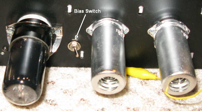
Switch toward small tubes = bias for small 6V6. Switch toward big tube = bias for big 6L6 or EL34.
To get the most out of a 6L6 or EL34 tube you also need to adjust the speaker impedance switch. To connect an 8 ohm speaker set the amp's impedance switch to 16 ohms, or connect a 4 ohm speaker with 8 ohm impedance selected. Doing this optimizes the output transformer load (4.5K ohms) placed on the 6L6 or EL34 and will usually result in higher output and better tone and better low frequency response. The primary impedance of the Special 6 Ultra's output transformer is 9K ohms so it's cut in half by using this technique.
If you're like me and your cab has a 16 ohm speaker you can drop the impedance by plugging a second speaker into the Ultra's second speaker jack. Using two 16 ohm speakers together will drop the impedance to 8 ohms so you would select 16 ohms on the Ultra's speaker impedance selector. Using a 16 ohm speaker with an 8 ohm speaker will drop it to 5.3 ohms so select 8 ohms. Using a 16 ohm speaker with a 4 ohm speaker will drop it to 3.2 ohms.
Dual Speaker Output With Big Power Tube
Speaker 1 Speaker 2 Impedance Ultra's Speaker Impedance Switch Setting
16 ohm 16 ohm 8 ohm 16 ohm
16 ohm 8 ohm 5.3 ohm 8 ohm
16 ohm 4 ohm 3.2 ohm 8 ohm
8 ohm 8 ohm 4 ohm 8 ohm
8 ohm 4 ohm 2.7 ohm 4 ohm
4 ohm 4 ohm 2 ohm 4 ohm
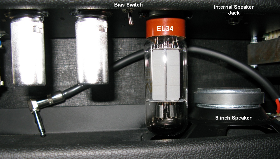
The EL34 and 6CA7 seem to be the most popular high power tubes for the Special 6 line of amps. Many are describing excellent tone, distortion and controllability along with the most volume possible. I went with a Valve Art EL34 sourced from eBay for $30 delivered. Another recommended EL34 is the Svetlana-Winged "C" EL34's but they're expensive.
Big EL34 Tube With Bias Switch Set For Big Tubes
Here's a quote from the Marshall Forum discussing the difference between the EL34 and 6CA7 tubes:
The EL34 is a pentode, while the 6CA7, which delivers a similar range of power output, is a beam tetrode which RCA referred to as a beam power tube. Although power pentodes and beam tetrodes are based on different principles of operation and have different internal constructions they are functionally closely equivalent. That being said, they both sound different. The EL34 for the most part has a creamy sound with a little grit (crunch). The 6CA7 has a tight bottom end and good mids with articulate highs. A lot of people call them a small version of a 6550.
Some good sounding 6L6 type tubes are the standard JJ 6L6 and the Sovtek 5881 (6P3S-E equivalent). The 5881 can be found for around $16. The Russian 6P3S is also a good, inexpensive choice at about $4 each.
Negative Feedback Mod
Many amps have a negative feedback loop to increase headroom (reduce overdrive), flatten frequency response and maintain better control of bass frequencies. This a Fender F52A style negative feedback mod. A more complicated AA964 style NFB is another option with this amp. I wanted a switched and variable negative feedback loop as an additional tone shaping option.
The Negative Feedback Mod on this page describes removing the driver tube's cathode bypass capacitor (C22) which will reduce the amp's overall output and reduce power tube overdrive distortion. A better mod would be to use a 3-way ON/OFF/ON SPDT switch like this 5E3 Fender Deluxe feedback switch which gives you: Normal (no feedback with bypass capacitor for highest gain) / No Bypass Capacitor (moderate gain) / Feedback (lowest gain and highest headroom and civility).
5E3 3-Way Feedback Switch
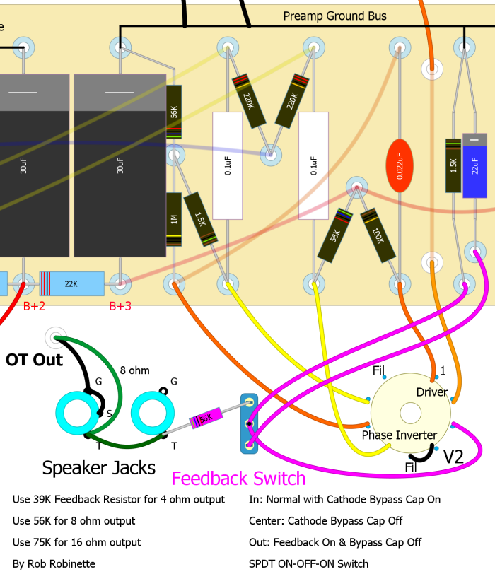
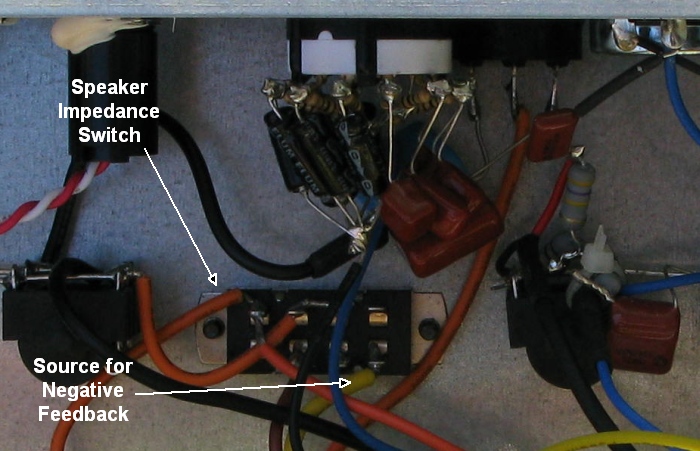
Inject Negative Feedback into blue wire.

Run a wire from the output transformer's 4 ohm (yellow wire attached to speaker impedance switch) output to a 100k ohm linear pot, then to an on/off toggle switch then to the blue wire connecting C22 and the output tube (V3, see pic below). You can try the feedback loop leaving capacitor C22 in place but I found it soaked up most of the feedback signal. C22 is the driver stage cathode resistor bypass cap and it helps boost the gain of the driver stage. Clipping the near capacitor leg will remove it from the circuit and it will have an effect on the amp but the feedback loop will be much more effective. You can use an alligator clip to temporarily reconnect C22's clipped leg for testing. You may prefer the amp's original tone or you may like the amp's tone with or without feedback and no C22.
Typical values for negative feedback resistors run from 22k ohms to 56k ohms so somewhere between 2 and 6 on the knob should sound good. The switch completely removes negative feedback. You can temporarily use the adjustable pot to find your NFB 'sweet spot' then measure the pot's resistance and install a resistor of that value in place of the pot. tdpri user Lazer used a 3-way switch for: OFF / a little feedback / a lot of feedback.
Yellow Wire is Source for Negative Feedback Signal
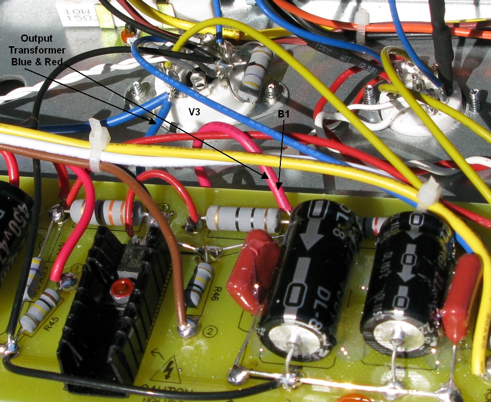
You also have to reverse the blue and red wires from the output transformer (labeled "Swap for Negative Feedback" in schematic above and highlighted in pic below) to make the negative feedback mod work. If you don't swap the two wires you'll hear squealing when you activate the feedback because the feedback signal is out of phase (becomes positive feedback). The red and blue wires run from the output transformer under the circuit board and come out to connect the blue wire to the output tube (V3) and the red wire to "B1" on the circuit board. Simply unsolder and swap the two wires.
Tone Stack Tone Pot Mod
The Special 6 Ultra comes with a fixed value Fender Blackface style tone stack and a classic Fender Princeton type tone knob for controlling tone. The tone stack is a passive circuit so it can't boost any part of the signal but simply acts as a three part filter to block treble, mid and bass to change the signal's tone.
It's very easy to add one to three more tone knobs to the tone stack (shown as Treble, Bass and Mid in schematics above and below). I chose to add all three to the back of the chassis to allow fine tuning the tone. Keep in mind the added tone controls will interact with one another and also affect the original tone control. For example when you turn up the mid control the treble and bass levels change too. Also the tone stack and original tone knob are affected differently by the amp's "boost" circuit (pulling the volume knob up). The mid control is the least effective so adding just the treble and bass controls will reduce complexity and give you more space to work with.
If you're going to add all three controls I recommend using mini-pots to make the tight fit in the chassis easier. I couldn't find a 10k or 50k audio mini-pot so I used a 100k audio mini-pot for the mid control. Each of the tone pots will have three connections. The two outside pot terminals are connected to each end of where the removed resistor was. All of the pots' middle terminals are connected to a capacitor.
I wanted to make this mod as easy as possible to reverse so I just clipped one leg of the 4 resistors instead of actually removing them (see pic below).
If you are installing 3 tone pots then simply wire them as shown in the "How to Wire 3 Tone Pots" diagram below.
For a bass tone pot you replace R15 with a 250k ohm audio (same as logarithmic) pot. Connect C16 to the bass pot's pins 2 & 3. Connect the wires from R14 and R16 to the outer two pot terminals (see diagram below).
For a treble tone pot you replace R13 and R14 with a 250k ohm audio pot. Connect where the two resistors were to the two outside terminals of the treble tone pot. The center terminal of the tone pot is connected to the white wire that runs to C18 (C18 is not visible in pic below). The white wire is connected to the volume pot so you can tap in there for a shorter wire run.
For a mid tone pot you replace R16 with a 25KA or 50KA ohm audio (log) pot. I couldn't find either in an audio mini-pot so I went with a 100k audio mini-pot but 25KA would be my recommendation. Connect where R16 was to the two outside terminals of the mid tone pot. The output side of R16 is connected to a red wire which runs to the volume pot--you can connect to the red wire at the volume pot to shorten the wire run. Connect C17 to the mid pot's pins 2 & 3.
Another option for the mid tone pot is to use a higher value 250KA pot which turns it into a "Raw" control. As the pot's resistance increases (turning the pot "up") then entire tone stack is bypassed more and more because all the filtering done by all three tone controls flow through the mid pot's ground connection. A raw control lets you control how much tone stack you get. A you turn the raw control up you get more unfiltered "raw" guitar tone. I placed an ON/OFF SPST mini switch between the mid pot and ground on my 5F6A Bassman to completely remove the tone stack. I get a significant signal boost when the raw control is on, even when all three tone controls are maxed. You can also fine tune the amount of volume increase given by the "Boost" control with a 250KA mid pot. There will be less volume boost with the mid pot turned up high.
To see how the tone controls function and their interaction check out the very cool and free Duncan Tone Stack Calculator. It graphically shows what turning the three pots do to the tone. Select the "Fender" tone stack and play with the pot controls. Be sure and change the value of the mid pot to 250KA to see how a "Raw" control works.
How to Wire 3 Tone Pots
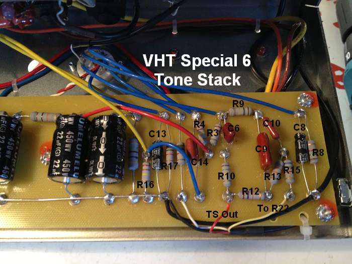
"To R12" connects to the red wire running from R16 to the volume pot. "To C18" connects to the white wire running from R13 to the volume pot (see photo below). C15 is the signal input to the tone pots, R12 is the signal output. View of diagram is of tone pot bottom.
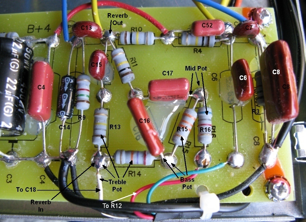
Special 6 Ultra Tone Stack Before Modification
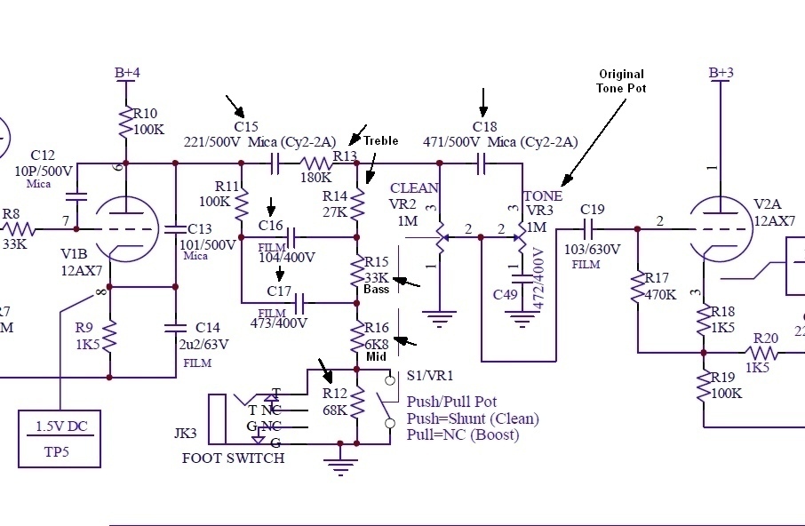
Treble pot replaces both R13 and R14. Bass pot replaces R15. Mid pot replaces R16.
Typical Fender Tone Stack
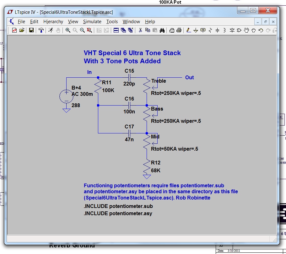
Modified Ultra Tone Stack
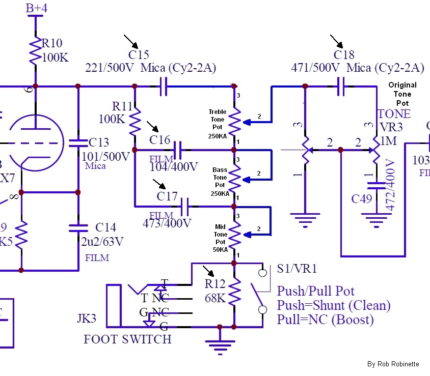
1, 2 & 3 refer to the tone pot pin numbers. The Bass and Mid pots are wired as variable resistors with a jumper between pot pins 2 and 3.

Pot pin numbers run 3 2 1 when viewing them from this side.
If you use 250k Audio pots for bass and treble, and 100k Audio for the mid pot, the factory fixed resistors are roughly equivalent to 45% of treble pot turn clockwise (up), 30% of mid pot turn and 42% of bass pot turn. These numbers take into account the logarithmic scale of the audio tone pots. Using a 25k or 50k audio pot for the mid control would move the factory setting closer to 50%.
Delete (or just clip one leg) R13, R14 for Treble Pot, R15 for Bass Pot, R16 for Mid Pot
4 Clipped Resistors & Wiring
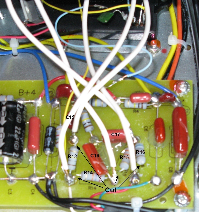
White wires run to new tone pots
New Tone & Reverb Controls
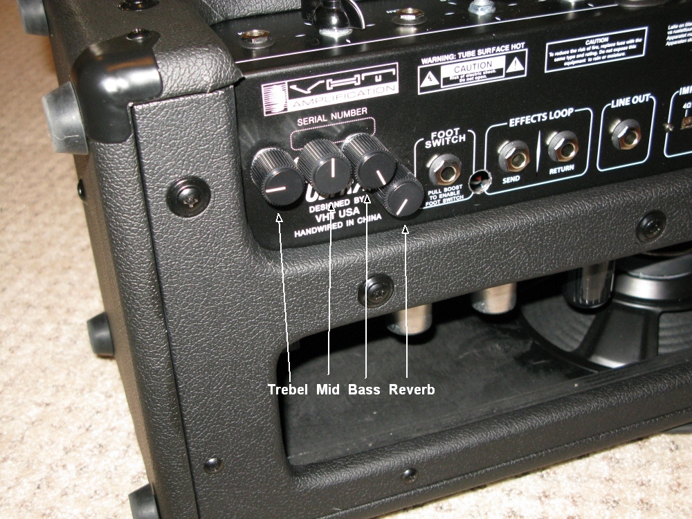
I had to pack my controls in tight because I had already installed the reverb pot. Using a wider spacing will allow you to use a wide variety of control knobs. I had to use small diameter knobs because of the tight spacing.
I created an LTspice file with the Ultra modified tone stack available here.
Special 6 (non-ultra) Tone Stack
VHT has stopped printing component labels on their circuit boards. Component numbers in the pic match the schematic below.
To install tone pots in the Special 6 (non Ultra) you would: Treble, replace R10 and R12 with a 250KA pot and wire it like the Ultra 6 mod above. Bass, replace R13 with a 250KA pot. Mid, replace R15 with a 25KA pot. Click the image to see the whole Special 6 schematic.
Convert the Boost Switch Into a Raw Switch
By simply clipping resistor R12 (bottom center in schematic below) you can convert the Boost Switch and Foot Switch to a Raw Switch. A Raw Switch removes the TMB (treble mid bass) tone stack's connection to ground which completely eliminates it from the amp circuit. The result is a very boosted raw (unfiltered) signal. This works well with equalization pedals because the pedal can be used to shape the entire, raw signal from the guitar. You get the full tone stack when the boost switch is off (switch closed) and no tone stack when it is on (switch open).
Clip resistor R12 and the Boost Switch and Foot Switch become a Raw Switch.
BitMo V-Verb Digital Reverb Kit
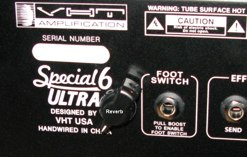
Reverb Knob on Back
The $60 BitMo reverb kit is fairly easy to assemble and install by following the included instructions. This reverb system samples the signal just before the tone stack and creates a digital reverb which is injected back into the signal path between the treble resistors in the tone stack. With the reverb turned fully down the amp's analog signal is unchanged.
The kit comes with a Belton Medium digital reverb module, 2931 or 1951 voltage regulator (converts 6.2v DC to 5v DC), 10k reverb pot with matching "chicken head" knob, two 100 ohm resistors (1 resistor is on the pot's middle terminal), two .012µF capacitors and 4 colors of 22 gauge wire. The reverb pot has a 1/4" smooth shaft. The "Reverb In" and "Reverb Out" connection points are shown above in the "Tone Stack" section circuit board picture. The "Reverb In" signal source is the junction of resistors R10 & R11. The "Reverb Out" goes to the junction of R13 & R14.
Reverb Kit Installed
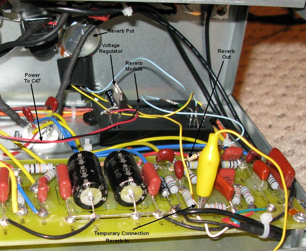
The yellow alligator clip is temporarily holding the "Reverb In" yellow wire to the R13 & R14 junction for testing.
Note: If you have added a treble tone pot to the tone stack you can connect "Reverb In" to the treble tone pot's center terminal for a shorter wire run.
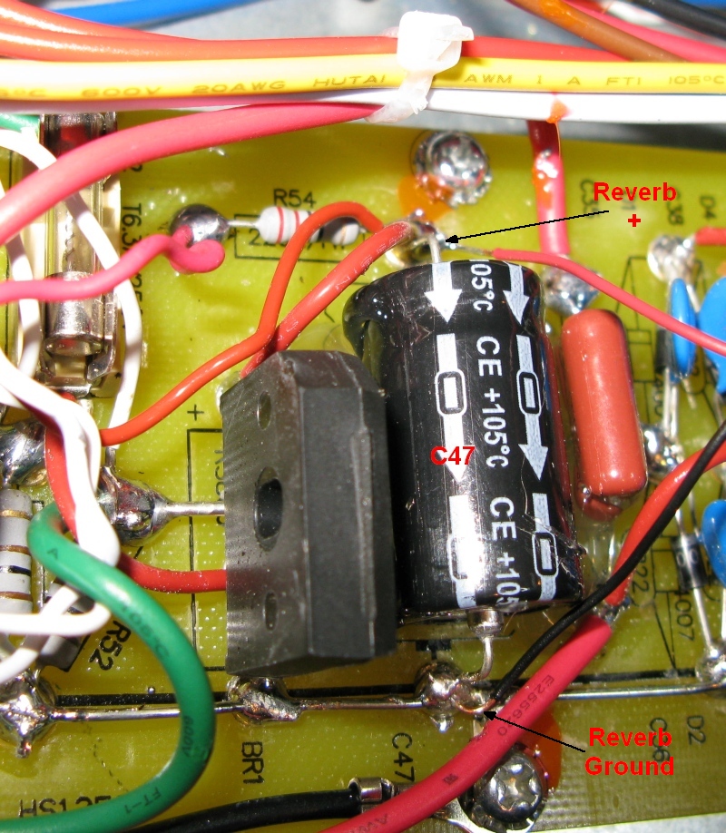
Reverb Power & Ground Connections
Add an Internal 8 Inch Speaker to the Amp Head
I wanted to add a small speaker to the amp head to allow easy low volume practice without having to carry a separate speaker cab around. I initially tried to add a 5 inch speaker to the back grill area but the Jensen Mod5-30 was slightly too large to fit. A 4 inch speaker will fit though. I decided to try a downward firing 8 inch Celestion Super 8, 15 watt 8 ohm guitar speaker. The speaker was $27 from MCM Electronics. It's a "vintage" style speaker with a pretty thin magnet so it's only 3 inches deep and weighs less than 2lbs. It's a tight fit but it doesn't add too much weight. I put the speaker as far right (looking from the rear of the cabinet) as I could to prevent interference with large 6L6 output tubes. If you don't want to work hard to stuff an 8" speaker in there I recommend you use the great sounding Eminence 620H 6 inch hemp cone speaker.
I had to work hard to stuff the 8 inch speaker in the cabinet so a 7 inch or smaller will fit easier. For the 8 inch I shortened a jigsaw blade so it was just long enough to cut through the bottom panel which is about 6/10 of an inch thick. I did that because at the sides of the hole you'll hit the side panels. The Super 8 will fit without cutting the side panels and you don't want to cut them because that would seriously weaken the cab. I shortened the jigsaw blade by putting it in a vise and bending the blade back and forth until it broke cleanly. I did have to file a little of the side panel to let the speaker drop in completely flush with the bottom of the cabinet. After test fitting the speaker I removed it and spray painted the cut wood with flat black paint. I put painters tape around the hole on the bottom to keep from getting any paint on the bottom of the cab. I also test fit a Weber 6"x9" guitar speaker but the big speaker magnet would interfere with big 6L6 tubes.
Celestion Super 8 Installed
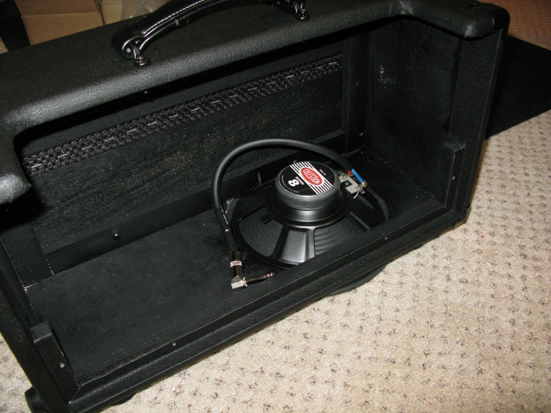
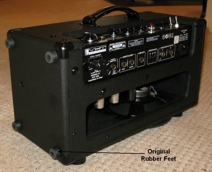
The speaker sounds fine with the cab in the normal upright position with most of the sound coming from the cab vent. For more volume place the cab on its side and it sounds better and louder. I picked up some 1 inch tall rubber feet on eBay to replace the amp's short feet to raise the amp off the floor to give room for the speaker grill. I put the original rubber feet on the side of the cab. I used the screw holes for the corner protectors but had to use slightly longer screws to secure the original rubber feet to the cab side.
Bottom Mounted Celestion Super 8 Speaker
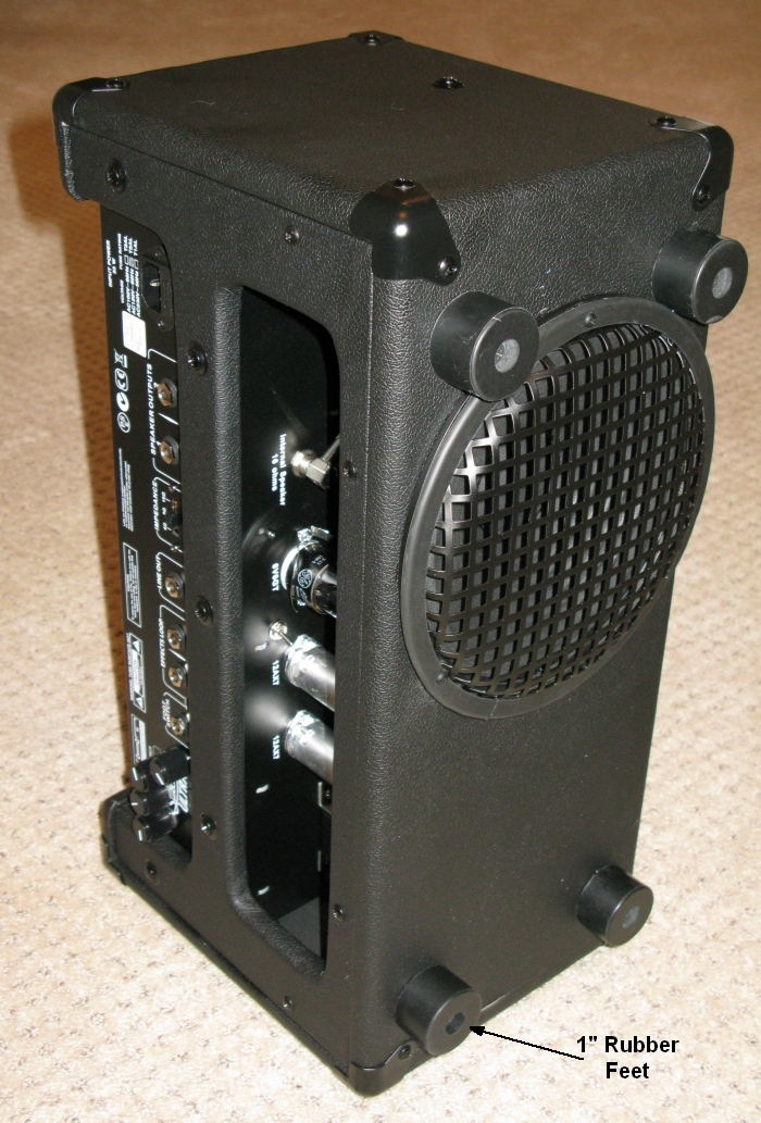
I sourced the generic 8 inch speaker grill from MCM electronics for $4. When I placed my amp head on top of my speaker cab the amp's speaker grill made contact with the cab's handle. I was able to gently bend the speaker grill inward enough so it didn't contact the cab handle. The bends in the grill are smooth and the grill still looks good.
I cut a 3 foot amp speaker cord to connect to the speaker terminals. I put a 90 degree cable plug on the cable and soldered the cable plug and the speaker connections. I plugged the cable into the internal speaker jack I added (see below). You can also just use one of the amp's rear speaker jacks.
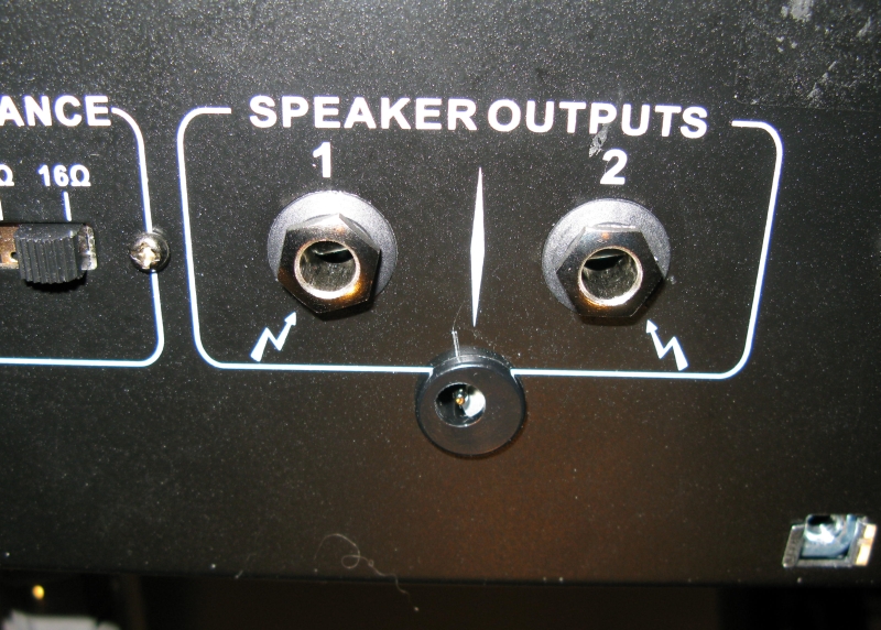
Add Internal Speaker Jack to the Special 6 Ultra Amp Head
The Special 6 Ultra amp head has an empty hole in the chassis where the combo unit has a speaker jack. I added this jack so I could plug in the 8" internal speaker I added to my Ultra amp head. To add a jack simply install a non-switched 1/4 inch TS jack in the empty hole and connect it to the external speaker jacks' connections. The new jack's sleeve connects to the ground wire (external speaker jacks' bare wire closest to the chassis wall). The new jack's tip connects to the external speaker jacks' bare wire that connects to the orange wire coming from the impedance switch (see pic below)
The two external speaker jacks non-switched and are wired in parallel meaning if you plug in two speakers both will get an output signal but keep in mind the speaker impedance will drop when running two or three speakers in parallel. The new jack's impedance is controlled with the impedance switch just like the two external jacks.
If you want to automatically disconnect the two external speaker jacks when the internal speaker jack is in use then you would need to use a 1/4 inch switched TS jack like this Neutrik Rean NYS2122. Reroute the orange speaker output wire (runs from impedance switch to output jacks) to the new switched jack's tip then wire the new jack's switched tip out terminal to the external speaker jacks' tip. You will also have to connect the new jack's ground to the output jacks' ground--no switching of the ground is needed.
You should also consider adding a non-connected "dummy jack" so you can plug the internal speaker cable into it to keep the cable from flopping around when not in use. Just drill a hole near the internal speaker jack to accept a TS jack. Since the real jack is labeled you'll know the unlabeled jack is the dummy.
Internal Speaker Jack Added
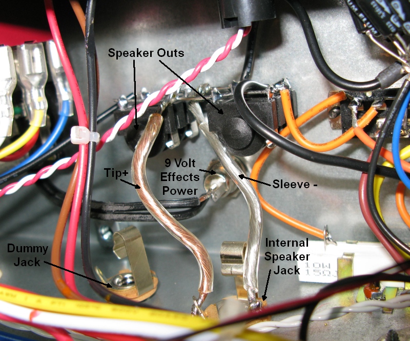
This internal speaker jack is non-switching. It is simply connected in parallel with the two speaker output jacks.
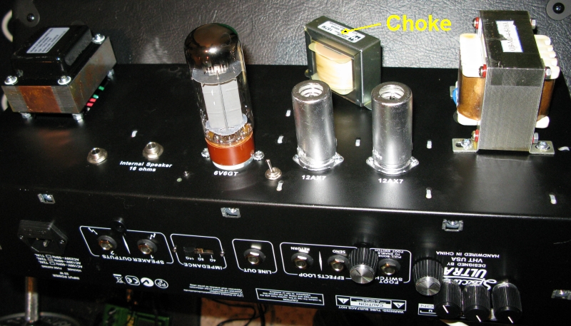
Add a Choke
Adding a choke to filter the power supply can help quiet the amplifier by removing buzz and hum. A choke can also alter the tone of the amp due to the "lag" induced by its wirewound core. If you plan to stick with the stock size 6L6 tubes you can get away with a smaller 75 milliamp rated choke but if you plan to run the bigger 6V6, EL34 or 6CA7 tubes you should get a 100 milliamp rated choke. A 5 to 10 Henry rating should work well and the choke must be rated for a maximum of 400 volts DC. I went with the Hammond 157M rated at 8 Henry 100 milliamps 259 ohms 400 volts.
Hammond 157M Choke

To install the choke you must replace Resistor R43 with the choke lead wires. Just clip one resistor leg and bend it slightly out of position so you can re-solder it if you want to reverse this mod, then solder the choke wires to where R43 was soldered. The choke wires are not polarized so it doesn't matter which wire goes to which end of R43.
The Hammond 157M is a medium size choke so it will fit on the power transformer end of the chassis. I had to place mine on the Output Transformer end of the chassis to clear the speaker I added to the amp head cabinet. You have to be careful how you mount the choke. You don't want its magnetic field interacting with the tubes, power transformer or output transformer. I actually powered up the amp and moved the choke around on the chassis to find the location to minimize hum. It turns out the location isn't that critical. Be careful drilling the mounting holes to keep from damaging the circuit board or wires. You can use drill stops to keep from penetrating too deep into the chassis. I used small self tapping sheet metal screws with a little Loc-Tite Red to keep them secure. Also be sure and twist the choke lead wires to minimize noise.
Replace Resistor R43 with Choke Leads
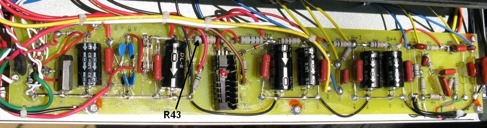
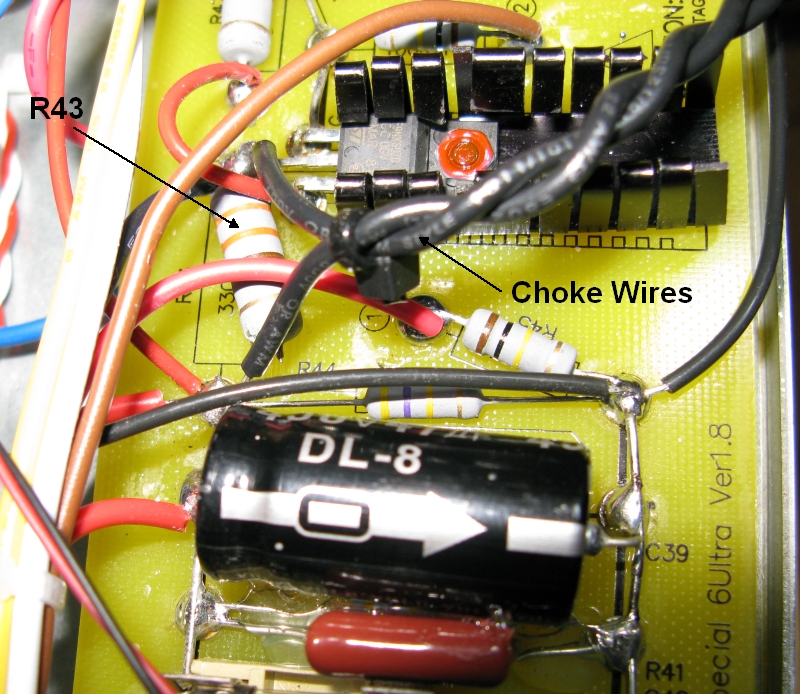
Note R43's clipped leg and its slight displacement. Choke wires connect to R43's solder pads. I put a small zip tie on the choke wires after twisting them to keep them from unraveling while I soldered them into place.
Add 9 Volt Pedal Power Jack
The Special 6 Ultra's big brother, the Special 12/20RT, comes with a 9 volt power jack to power your effects pedals. I thought that was a good idea so I installed a 9 volt power supply internally and routed it to an external jack. I went with a high quality purpose built Godlyke Power-All 9 volt Basic Kit. You need a 9 volt adapter rated for at least 2 amps (2000 milliamps). The biggest gotcha with this mod for me was figuring out that I needed an insulated 9 volt panel jack. Effects pedals use a nonstandard power connecter with + power on the outside (barrel) and - on the inside center pin. If the power jack isn't insulated from the chassis the plug will short its power to the chassis. I found these plastic 2.1mm x 5.5mm DC power plugs on ebay using the search, "9 volt panel mount." They are also available at Mouser.com.
Insulated Plastic 9 Volt Panel Mount Connector

Center pin is 2.1mm and hole is 5.5mm. Connect - to center pin, + to barrel (this is the reverse of the norm). This is Mouser.com's part number 163-4302-E $1.51 each.
Godlyke Power-All 9 Volt Wall Wart

Godlyke Power-All heavy duty 9 volt power adapter opened. There is one small screw under the round "Inspected" decal. Black and white wires sticking up are 115 volt in hot (black) and neutral (white). 9 volt DC jack will be attached to DC output wires on left. Power plug prongs were removed (lower right) with pliers.
9 Volt Power Adapter Installed
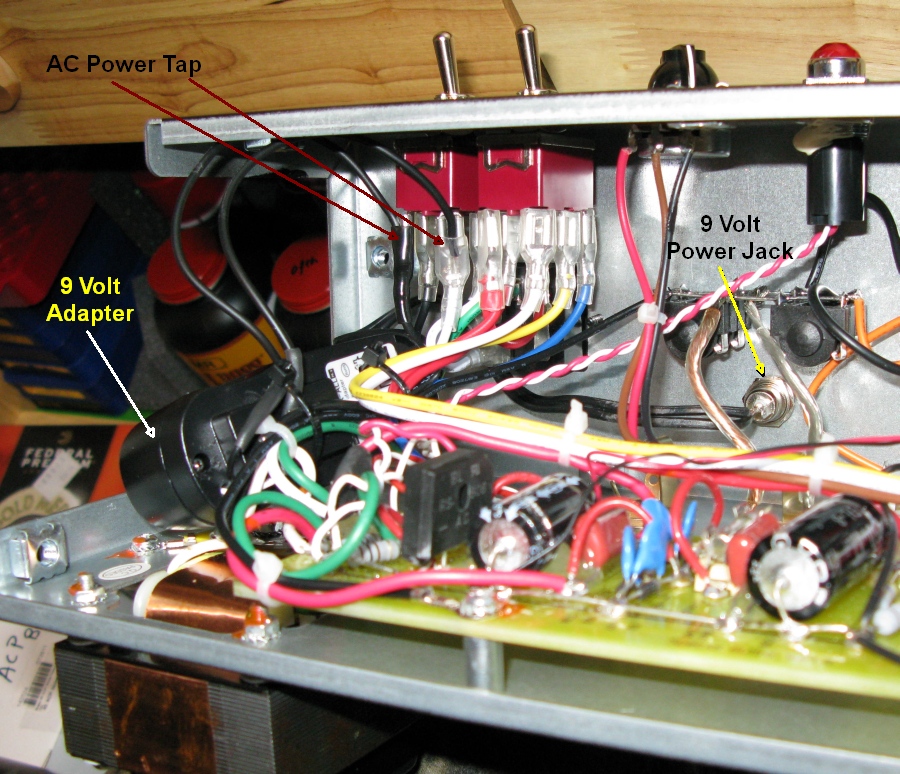
Switched 115 Volts tapped at On/Off Switch output. 9 Volt Power Jack (mid right) must be insulated from the amp chassis. Later I went back and twisted the AC power wires running from the On/Off Switch to the power pack to minimize 60Hz hum and noise.
I soldered the 115 volt power wires directly to the slide-on connectors on the "On/Off" switch's output. I zip-tied the power supply to the AC power wires as shown above. The Power-All Kit comes with a "chain" cable that will plug into your new 9 volt power jack but you can also get a power extension chord on eBay. Look for 2.1mm x 5.5mm plugs, that's the standard size for effects pedal power plugs. I found a 6 foot male-to-male extension chord for the Sanyo Pedal Juice for $8 delivered.
9 volt effects pedal power outlet.
Be sure and verify your effects pedals take the standard 9 volts with the + on the outside barrel. One of my pedals wanted + on the center pin. The Power-All Kit comes with a short chord that reverses the power to work with pedals like this.
Reduce Volume Boost Volume Change
Some people complain that pushing the Foot Switch for Volume Boost results in too much volume change to be useful during a live performance (pulling up the Volume Knob also engages Volume Boost). Volume boost is engaged by adding resistor R12 (68k ohm located on the volume pot) to the tone circuit. Adding R12 reduces the amount of signal that bleeds to ground through the tone circuit which boosts the volume. Because of this the Volume Boost does affect the signal's tone. With the boost control you either have 68k ohms with boost or 0 ohms with no boost (clean). Decreasing the value of R12 will reduce the volume change when Volume Boost is engaged.
Volume Boost R12 at Bottom Center
Bottom center: Foot Switch, Resistor R12, Volume Knob push/pull.
You can simply remove and replace R12 with a lower ohm resistor or you can add a resistor in parallel to R12 to reduce the boost volume change. You can even use alligator clips to temporarily add a parallel resistor so you can try different value resistors until you get the volume change you want. Just put an alligator clip wire on each leg of R12 and clip the other end of the wires to the new resistor's legs. To calculate what the parallel resistance of the two resistors use this formula: Total Resistance = 1/(1/68000 + 1/new resistor). If you add another 68k ohm resistor in parallel the total resistance drops by half to 34k ohms. Another option is to replace R12 with a 100k full size pot or small trim pot for variable boost.
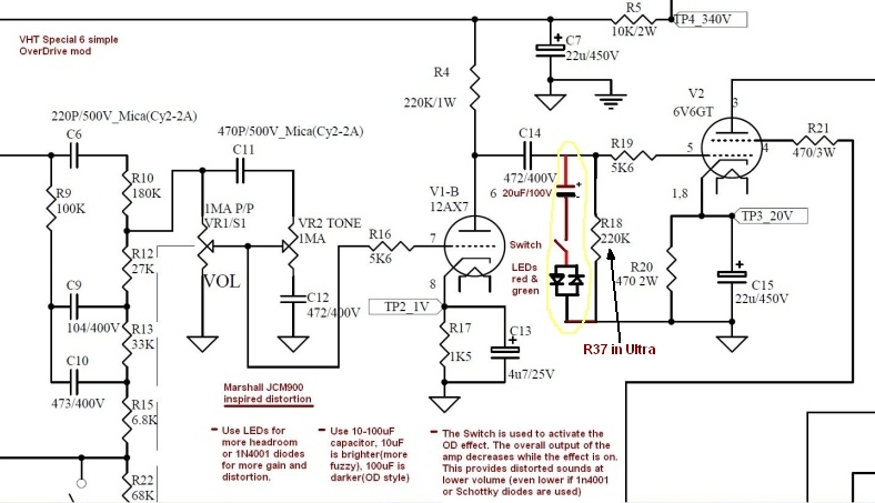
Guitar Dreamer Distortion/Overdrive Mod
This is a cool and simple mod to add overdrive and/or distortion to the Special 6 or Special 6 Ultra. This mod really isn't needed on the Ultra because you can get real tube overdrive and distortion from the Ultra preamp stage at low volume but it's such a simple mod it might be fun/instructional to do it anyway.
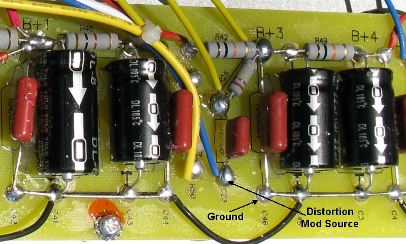
To install this in the Ultra you simply place the circuit on the output solder pad of capacitor C23 on the circuit board as the signal input and use the C46 ground pad (see circuit board pic below) for ground. The easy access to these points makes it easy to use alligator clips to temporarily insert the distortion circuit for testing. This makes it easy to experiment with different types of diodes & caps to get the distortion just the way you like it.
You could replace this mod's on/off switch with an on/off/on 3-way mini-toggle switch to install both, a smooth overdrive using red & green LEDs on one set of switch terminals and install 1N4001 or Schottky diodes for a heavy distortion on the other. The 3-way switch would allow you to select off, overdrive or distortion.
The circuit is simply a 20uF 100v capacitor and two diodes (or three diodes for asymmetrical clipping). Be sure and read the notes Thanos placed on the schematic below. Here's a quote from Thanos' blog:
"The diodes used could be almost anything but the most common diodes are 1N4001 (silicone) type and LEDs. Different diodes produce different distortion sounds. All diodes decrease the overall output volume of the amp when the distortion effect in "On". LEDs (red & green) sound smoother (overdrive style) and have more clean headroom. 1N4001 diodes sound brighter (distortion style) and have more clipping distortion with less clean headroom. Schottky type diodes sound more distorted ("metal") and have the lowest headroom."
The details of the mod are here: Guitar Dreamer Distortion Mod. See Tube Guitar Amplifier Overdrive for specific information on how overdrive distortion is created in a tube amplifier.
Thanos' Distortion Mod Schematic
Special 6 (non-Ultra) Schematic
Add Distortion Circuit to Ultra's C23 Output & C46 Ground
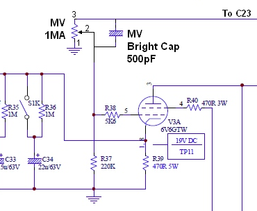
Master Volume
A 'Master Volume' control allows you to turn down the output from the preamp so you can use the Ultra channel to get preamp overdrive distortion but then turn down this distorted signal and feed it to the power tube for low volume practice. You can also use this control to change the balance between preamp overdrive distortion and power amp distortion to finesse your OD tone.
The Master Volume mod involves inserting a 1 mega ohm audio (or logarithmic) pot between the driver tube (V2B) and the power tube (V3), or more precisely stated between capacitor C23 (coupling capacitor) and resistor R38 (power tube grid stopper resistor). You can locate R38 by following the wire connected to the power tube socket (V3) pin 5.
I recommend you install an optional 'bright cap' to keep the tone from getting too dark when you turn the Master Volume down low. Solder a 250pF or 100pF (25 volt or greater) capacitor between the pot's pins 2 and 3. This allows high frequencies to bypass the tone control at lower volume. If you don't like the cap it is easy to clip it out later. Connect the wire from C23 to pin 3. Connect the wire from R38 to pin 2. Connect pot pin 1 to ground.
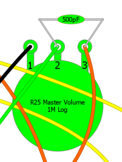
Master Volume pot and Bright Cap inserted between the driver and power tubes (C23 and R38). Numbers 1, 2 and 3 refer to the pot pin numbers. Bright cap and cap value are optional. 500pF is really too large and makes low volume too bright.
Effects Loop Send & Return Level Controls
The Special 6s' big brother, the Special 12/20RT has adjustable send and receive level controls. The effects loop send level is affected by the amp's volume and gain controls and can overwhelm some effects units. This mod allows you to adjust the send level to prevent the external effects processor from distorting or clipping. Reducing this send level control will reduce the amp's output volume so you normally want to run this control at max volume when no effects are plugged in. You may have to readjust this control when you change the Ultra or Clean volume when using external effects.
The mod to add a Send Level control to the Special 6 Ultra is pretty easy, you simply replace R21 with a 100K audio (or logarithmic) mini- pot and add a 1.5k ohm resistor as shown below.
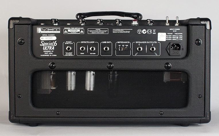
Special 12/20RT Back Panel
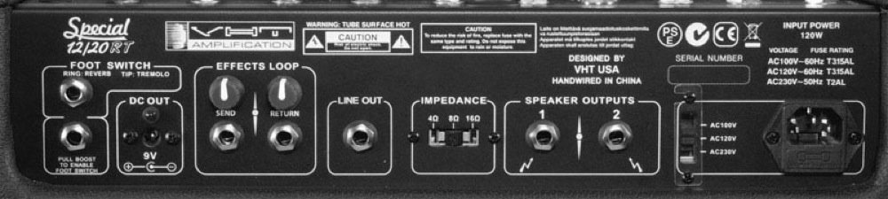
Note the Effects Loop level controls, 9v DC Out for effects pedal power, Reverb/Tremolo Foot Switch and international switchable power supply
Special 12/20RT Send & Receive Level Controls
Special 6 Ultra Send Level & Return Level Controls

Send Level control at lower left, Return Level at lower right. Numbers 1, 2 and 3 refer to the pot pin numbers.
Send Level Pot
Send Level Control Install
Drill a hole to mount the 100KA Send Level Pot. I placed mine below and between the foot switch and send jacks. Try to keep the metal shavings away from the two transformers and be sure and blow them out using compressed air. I attached the two wires and resistor to the mini-pot before I installed it. It's much easier to solder outside the chassis. Once the pot is installed it's pretty easy to bend the wires and resistor to make contact with their solder points.
1. Remove R21 (or just clip one leg). It is physically located on the send jack and runs between the tip and ground wires.
2. Snip C20's right leg where it connects to the blue wire on the return jack. Leave the leg as long as possible to ease soldering. C20 is just to the left of the return jack.
3. Wire the Send Level Pot's Pin 1 to ground (send jack's bare wire closest to chassis) with a short piece of black wire.
4. Wire the pot's Pin 2 to a new 1.5k ohm resistor then connect the resistor's other end to the send jack tip (a blue wire connecting the send & return jacks). I completely covered this resistor with a piece of shrink-tubing.
5. Wire the pot's Pin 3 to C20's right leg using a short piece of wire, preferably blue.
See Ultra schematic and pic below. I recommend using a mini-pot to save space.
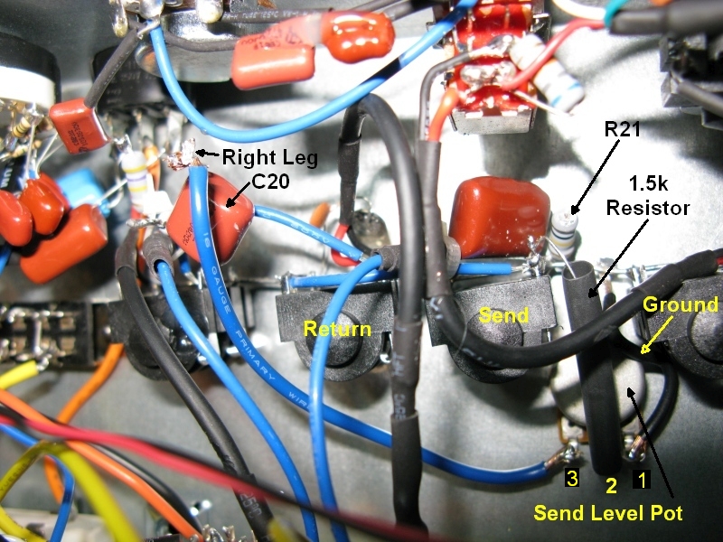
Send Level Pot
Pin 3 to C20's right leg. Pin 2's Blue Wire is located on the Send Jack. The Ground is also on the Send Jack.
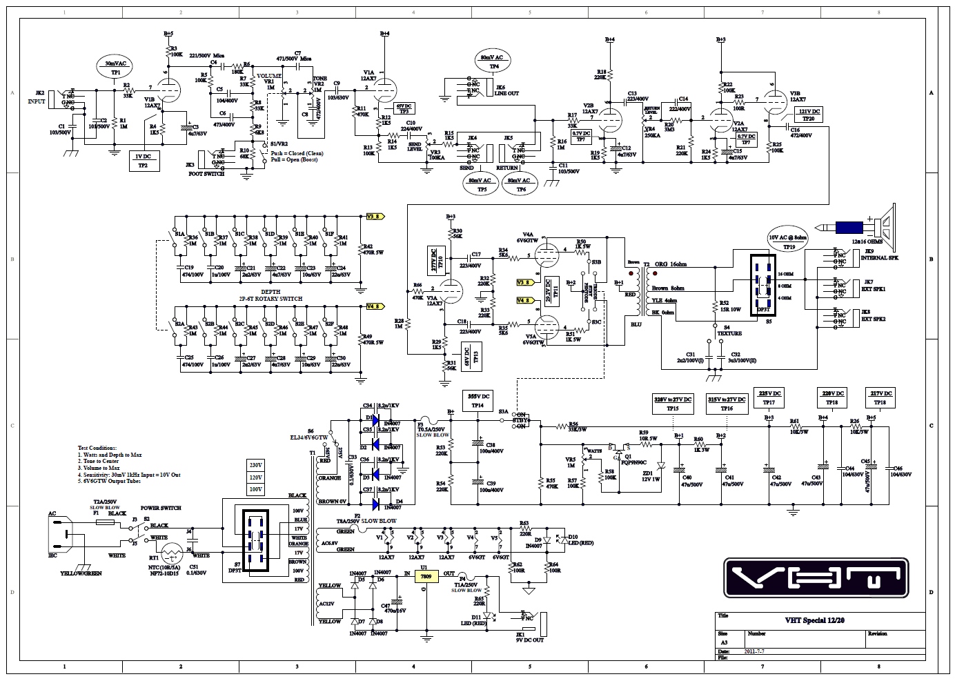
The return level control was a little more difficult to figure out because the Special 12/20 has a third 12AX7 tube between the return line and the return level control. I haven't done this mod but you would replace R22 (1 mega ohm resistor with brown/black/green stripes) with a 1 mega ohm audio pot with pin 1 to ground, 2 to R23, and 3 to the return jack tip. R23 is physically located to the left of the return jack--at the end of the blue wire coming from tube V2 (middle tube) pin 7. The full Special 12/20RT schematic can be seen here: full 12/20RT schematic.
VHT Customer Support on Adding Bass
Colin asked VHT Amplification regarding increasing the bass, they responded with these tips:
Here are some other ways to increase the bass:
1) Turn the Depth control fully clockwise. (DOH! LOL)
2) Increase C14, try 3.3 uF or 4.7 uF (this effects both Clean and Ultra channels). These capacitors only need to handle a few volts, so capacitors rated at 10 volts or more will be fine.
3) Increase C8, try 2.2 uF or 3.3 uF (this effects only the Ultra channel). These capacitors only need to handle a few volts, so capacitors rated at 10 volts or more will be fine.
4) Increase C23, try .01 uF or .022 uF. These capacitors should be rated for 400 volts (on the schematic, the stock capacitor is labeled as 472/400 volts, which is the same as .0047).
Hope this help, thanks for contacting VHT Customer Support
Special 6 Ultra Kleuck Tweed Mod
Kleuck explains the mod:
Well, the goal was to nail the spirit of the "Tweed era" (1950's Fender) with an amp between the 5F1/5F2/5E3. "Tweed "(last and more common ones at least) means: fast but soft break up, compression, loose lows.
This is due to the lack of negative feedback most of the time, not so large power (PT) & output (OT) transformers, small filtering caps, and huge filtering resistors in the power supply path. The PT of the SP6 is good (too good for the tweed tone), so I added dropping resistors before the rectifier bridge, to simulate a tiny power transformer and tube rectifier, this alone softens a lot the attack. I made R48 bigger for the same reason: a big screen resistor adds compression, not exactly the same as in a true tweed as the preamp supply is separated from the power amp supply, but sound-wise it works. I replaced the filtering caps with lower value ones for the same reason.
I removed the blackface tone stack because it was useless, and because it eats gain, as does the effects loop, so I modified the gain of the effects loop triode and added a light negative feedback to have just a hair more control on the lows.
That's all for the main mods actually, after that I replaced some caps for a more period-correct and juicy sound (yes, I hear differences between caps sometimes) and added a fast diode after the bridge to tame the "SS rectifier harshness," though I did not hear any in the SP6 or the SP6-Ultra (but it made a huge one in my EL84 Push-Pull, and the cost is very low, so...) Added a reverse protection diode on the MOS, not absolutely necessary, but... The mods on the Ultra channel have nothing to do with the tweed sound, on the contrary, I tried to make it sound more like a classic Marshall, I think it's more useful to have two different sound.
Click on kleuck's schematic below to see the full size schematic.
The (non-Ultra) Special 6 Schematic
The Special 6 has only two tubes, V1 for preamp and driver and V2 for power. The two inputs are an exact Fender 'tweed' era copy of dual Hi and Lo inputs. The Lo input is -6dB lower due to a voltage divider formed by the two 68k V1A grid stopper resistors that cut the input voltage in half. This guy has some very good Special 6 info and mods.
By Rob Robinette
References
RCA Corporation, RCA Receiving Tube Manual, RC30.
Merlin Blencowe, Designing Tube Preamps for Guitar and Bass, 2nd Edition.
Merlin Blencowe, Designing High-Fidelity Tube Preamps
Morgan Jones, Valve Amplifiers, 4th Edition.
Richard Kuehnel, Circuit Analysis of a Legendary Tube Amplifier: The Fender Bassman 5F6-A, 3rd Edition.
Richard Kuehnel, Vacuum Tube Circuit Design: Guitar Amplifier Preamps, 2nd Edition.
Richard Kuehnel, Vacuum Tube Circuit Design: Guitar Amplifier Power Amps
Robert C. Megantz, Design and Construction of Tube Guitar Amplifiers
Neumann & Irving, Guitar Amplifier Overdrive, A Visual Tour It's fairly technical but it's the only book written specifically about guitar amplifier overdrive. It includes many graphs to help make the material easier to understand.
T.E. Rutt, Vacuum Tube Triode Nonlinearity as Part of The Electric Guitar Sound
[ How the 5E3 Deluxe Works ] [ Deluxe Models ] [ DRRI & 68 CDR Mods ] [ Amp Troubleshooting ] [ My 5E3 Build ] [ Spice Analysis ] [ The Trainwreck Pages ] [ Fender Input Jacks ] [ B9A Prototype Boards ]