[ How the 5E3 Deluxe Works ] [ Deluxe Models ] [ DRRI & 68 CDR Mods ] [ Amp Troubleshooting ] [ My 5E3 Build ] [ Spice Analysis ] [ The Trainwreck Pages ] [ Fender Input Jacks ] [ B9A Prototype Boards ]

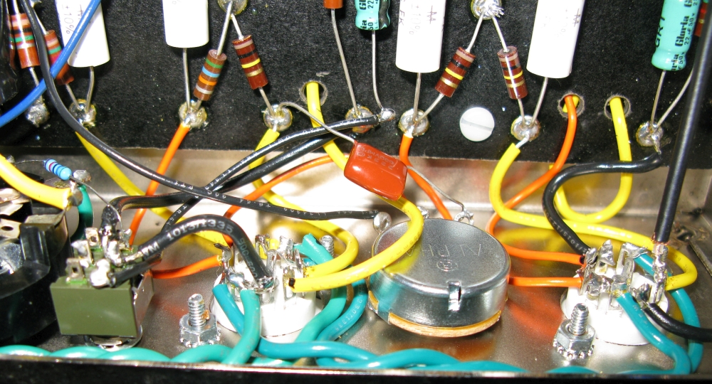
Photo by Rob Robinette
Generic Tube Amplifier Modifications
By Rob Robinette
Have comments or corrections? Email rob at: robinette at comcast dot net
WARNING: A tube amplifier chassis contains lethal high voltage even when unplugged--sometimes over 700 volts AC and 500 volts DC. If you have not been trained to work with high voltage then have an amp technician service your amp. Never touch the amplifier chassis with one hand while probing with the other hand because a lethal shock can run between your arms through your heart. Use just one hand when working on a powered amp. See more tube amplifier safety info here.
The following mods are not specific to any particular amp model and apply to many tube guitar amplifiers.
See these links for modifications specific to the 5E3 Deluxe, 5F6A Bassman, blackface and silverface amps.
List of Amp Mods
3-Way Negative Feedback Switch My favorite tube amp mod. Normal / None / Heavy selectable feedback.
Adjustable Bias Adjust your power tube bias for max output and sweetest tone.
Adjustable Balanced Bias Using a Balance Pot Adjustable bias with a balance pot to evenly bias unmatched power tubes.
Adjustable Balanced Bias Using Two Bias Pots Adds a second bias pot to evenly bias unmatched power tubes.
High Voltage Tap Adjustable Bias Tap your center tapped power transformer to create a 50v bias tap.
High Voltage Tap Adjustable Bias for Bridge Rectifiers Tap your bridge rectifier to create a 50v bias tap.
Tube / Solid State Rectifier Switch Saggy or firm rectification at the flip of a switch.
Add a Mid Tone Pot If you amp doesn't have one then add one
Raw (Tone Stack Bypass) Switch Remove all traces of the TMB tone stack at the flip of a switch for pure (raw) guitar tone.
Raw Control Raw pot allows variable tone stack bypass.
Framus Mid Tone Control Easy to make mid control.
Add a Bass Tone Control Keep bass for fat cleans, cut bass for tight overdrive.
Add a Bass Cut Control Keep bass for fat cleans, cut bass for tight overdrive.
Volume/Sizzle Control Wide range tone control.
Resistor Bright Cap Brighten your amp with a treble peaker.
Reduce 'ice pick' Highs If your speakers are too shrill this simple, subtle cap can help.
Voice a "Lead" Channel Tighten up and modernize one channel's clean and overdrive tone.
Lar-Mar/Trainwreck Type-2 Master Volume Old School master volume.
Master Volume + Vox Cut Control Master volume AND late-in-the-circuit tone control. I love this thing.
Standby/Mute Switch Simple mute switch.
Mute Switch Another simple mute switch.
Pre Phase Inverter Master Volume The preferred master volume for cathodyne phase inverter amps.
Switched Cascaded Channels for High Gain
One Wire Cascade This old JTM45 mod will cascade the Normal channel into the Bright channel for a high gain preamp.
Preamp Local Negative Feedback Tune the overdrive tone of a high gain preamp.
Gain Boost Switch Add more preamp gain for more dirt.
Switchable Plate Load Voltage Divider Reduce gain at the flip of a switch.
3-Way Preamp Bias Switch Hot - Cool - Normal preamp tube bias with and without bypass caps.
1/4 Power Switch Attenuation at the flip of a switch.
10% Power Switch For real bedroom level overdrive.
10% Power Jack Use your Aux jack as a 10% output jack
10% Power In External Box External box goes between your amp and speaker to dump 90% of amp power
1/2 Power Switch Pentode / Triode switch to cut power almost in half.
100 Watt Half Power Switch Switch out a pair of power tubes.
Paul C Mod - Cathodyne Phase Inverter Fixed Bias More balanced cathodyne output reduces nasty "double frequency" distortion.
FX Loop Simple passive FX loop.
FX Loop With True Bypass Passive FX loop with bypass switch.
Line Out Jack Simple way to feed the PA and recording rig.
Use Two Input Jacks Instead of Four Eliminate the "Low" jacks.
Bias Measuring Jacks Safely and conveniently measure power tube bias.
Channel Jumper Switch Leave your patch cord at home.
Fixed / Cathode Bias Switch Standard fixed or 5E5 Pro style round tubey warmth and compression.
Dumble Tweedle Dee Mods Howard Dumble modified 5E3 Deluxe Mods.
Add a VU Meter Give your audience something to watch as you play.
EL34 Compatibility Go Brit with EL34 power tubes.
Run 6V6 Power Tubes Less output power, small bottle tone with more power tube distortion.
Run 6L6 Power Tubes in a 6V6 Amp A tone change with little power gain.
Run 2 Power Tubes in a 4 Power Tube Amp Cut your output power in half.
Run 2 6V6 Power Tubes in a 4x6L6 Amp Cut your big amp's power by 65%.
Phase Inverter Grid Stopper Resistor Prevent nasty sounding cathodyne double-frequency distortion.
Power Tube Grid Stopper Resistors Add power amp stability and decrease blocking distortion.
Simulate Tube Rectifier Voltage Drop and Sag Using a Solid State Rectifier and Sag Resistor
Lower the B+1 Voltage Higher wall voltage can lead to high amp voltages.
Lower the Heater Voltage Keep your tubes in their sweet spot.
Humdinger Heater Hum Pot Adjust this pot for minimum 60Hz heater hum.
Heater Elevation Using a Voltage Divider Help your highly stressed cathode followers live longer and reduce heater hum.
DC Heater Power From 6.3VAC Fairly Easy DC Preamp Tube Heat
Standby Switch 'Pop Reduction' and Current Inrush Surge Protection Every standby switch needs this resistor.
Power Switch Pop Elimination Silence that switch.
LED Pilot Light Simple LED circuit using 6.3v heater power.
Add a Soft Start Inrush Current Limiter
Amp Protection Mods Protect your amp from expensive damage.
Using the Ground Switch Hole for Mods Be careful, it's noisy over there.
Add a 6" Practice Speaker to your amp head.
Tremolo Cut Switch Add gain by disconnecting the tremolo circuit.
Slow the Tremolo Slow is good.
Eliminate Tremolo Ticking Add one cap and it's gone.
Tremolo Always On RCA Plug Leave your tremolo foot switch at home.
Add a Reverb Dwell Control For Fender style reverb circuits.
Darken the Reverb Tone Is your reverb tone too bright? This easy mod can tune the tone.
RobRob Reactive Power Brake Speaker simulator to feed your mixing board.
Use an Arduino to Display Bias & Voltage How to interface an Arduino with your tube amp.
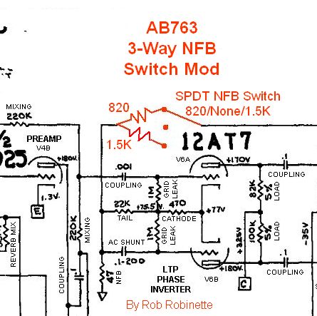
3-Way Negative Feedback Switch
This is my favorite and most useful amp mod, a three-way SPDT ON/OFF/ON mini-switch gives you: Normal feedback / No Feedback / Heavy feedback. The 'No Feedback' position makes the amp break up early kind of like a 5E3 Deluxe. The Marshall JTM45 was a direct copy of the 5F6A Bassman but the feedback signal was tapped from the 16 ohm output transformer secondary instead of the 5F6A's 2 ohm secondary resulting in the JTM45 getting 2.8 times more feedback. The extra feedback of the Heavy position makes the cleans cleaner and tightens up the boundary between clean and overdrive which can make it easier to control breakup with finger technique. It also makes the amp's overdrive tone cleaner, tighter and more Marshallesque.
When changing the feedback source from one output transformer secondary to another you change the feedback resistance by a factor of 1.41 for one step change (for example going from a 2 ohm speaker tap to 4 ohm), a factor of 2 for 2 steps (example 2 ohm to 8 ohm), or a factor of 2.83 for 3 steps (example 2 ohm to 16 ohm).

3-Way NFB switch in a 5F6A Bassman installed next to the speaker jacks for short wire runs.
In blackface and silverface amps I recommend removing the original resistor and connecting the switch to the two now empty resistor eyelets.
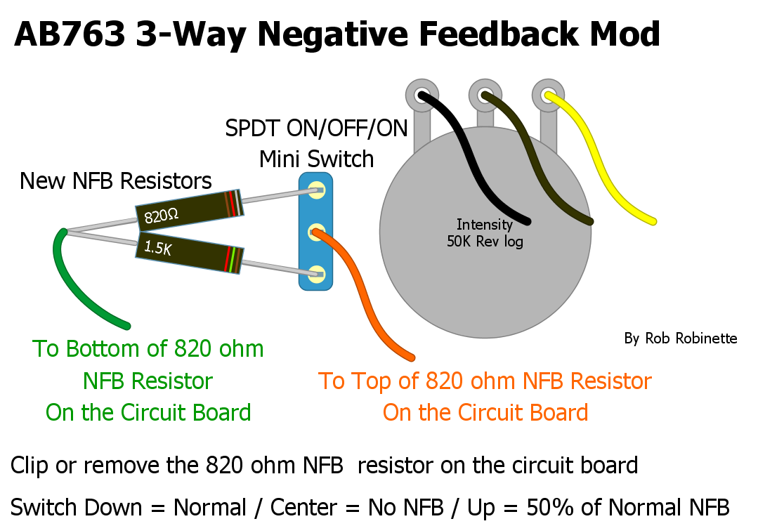
I suggest installing the SPDT ON/OFF/ON mini switch next to the tremolo intensity pot or on the back panel. Switch Down = Heavy NFB, Center = No NFB, Up = Light NFB.
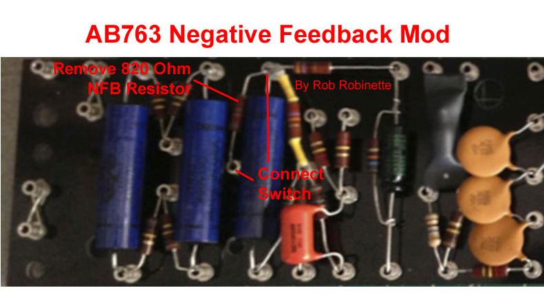
NFB mod for the Fender blackface/silverface amps. You must remove (or just clip a leg of) the original 820 ohm negative feedback resistor then connect the 3-way switch to the top and bottom resistor eyelets/turrets.
Speaker Tap and Feedback Levels for the 5F6A, JTM45 and Similar Amps
|
Speaker Tap |
5F6A Light Feedback |
Moderate |
JTM45 Heavy |
|
2 ohm |
27k 5F6A |
20k |
10k |
|
4 ohm |
39k |
27k |
13k |
|
8 ohm |
56k |
39k |
20k |
|
16 ohm |
75k |
56k |
27k JTM45 |
Moderate is 41% more feedback than Light. Heavy is 2.8 times more feedback than Light.
Adjustable Bias
To add adjustable bias to fixed bias amps with no bias pot you simply replace the bias circuit's second, larger resistor (connected to ground) with a mini-50k linear pot (or trim pot) and a resistor of about half the value of the original resistor. This mod allows wide range of adjustment to bias 6V6, 6L6, EL34, KT66, KT77 and KT88 power tubes.
The two bias resistors in a typical bias circuit form a voltage divider to reduce the voltage coming out of the bias rectifier diode. One or two electrolytic caps are filter caps to smooth out the pulsing DC from the bias diode.
If you find you run out of room and need to get a hotter bias then decrease the value of the second resistor. If you need more room on the cool bias end then increase the value of the resistor.
As you turn the pot clockwise the bias will get hotter (higher dissipation) as the negative bias voltage on the control grid will decrease toward 0v. For a new amp startup I recommend presetting the bias pot full down (counter clockwise, coolest bias). It's also a good idea to turn the bias down some before installing a new set of tubes and then bias them immediately upon power up. Always watch new power tubes for red plating upon first power up.
My Tung-Sol 5881 power tubes in my 5F6A biased at -45.1v on the grid, 443v plate, 40.7 milliamps (measured by OT shunt) for 69.3% of their rated 26 watts of plate dissipation. A set of JJ KT88's biased at -45.5v on the grid, 430v on the plates and 55ma of plate current for 68.7% of their rated 35 watts. That's with a JJ GZ34S rectifier tube. The Fender 5F6A schematic shows -48v as the bias voltage for 5881 tubes which would yield a significantly cooler bias.
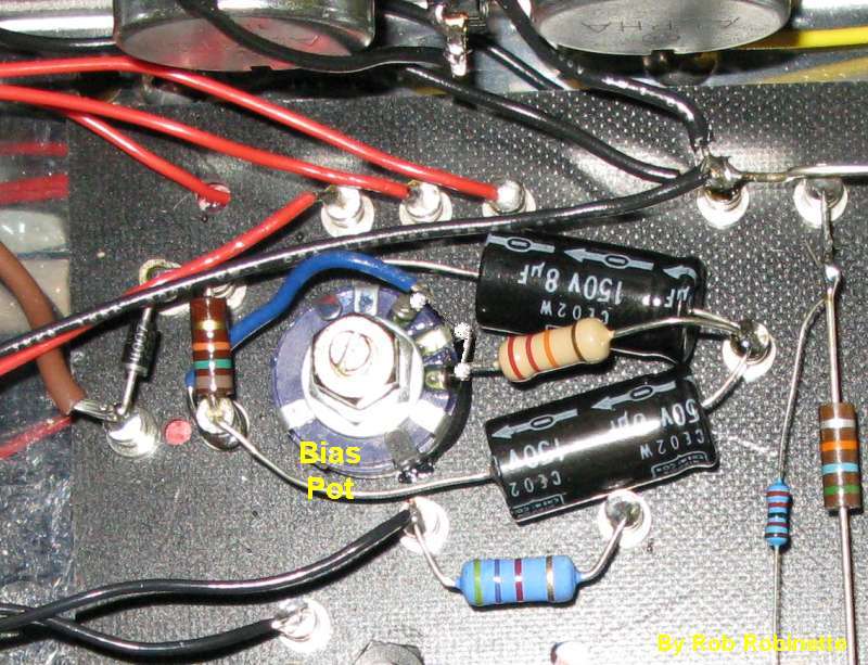
I glued my bias pot to the circuit board as shown in the layout below but you can mount it anywhere. Just run the blue bias wire to the bias pot's #3 terminal, connect the 27k resistor to the center (wiper) #2 terminal and use the resistor's lead to form the jumper to terminal #1. Then ground the other end of the 27k resistor at any convenient ground. Many people put the bias pot in one of the unused speaker jack holes. If you make the bias pot accessible from the amp's exterior I recommend you use a screwdriver slotted pot or this one to make it more difficult to accidentally alter the bias.
Standard 5F6A Bassman Non-Adjustable Bias
Adjustable Bias
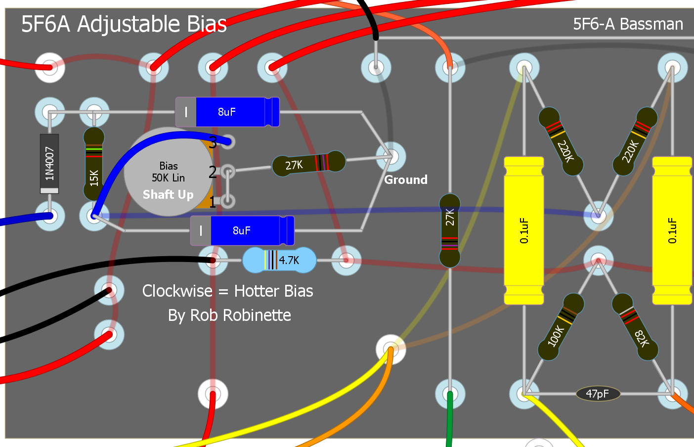
The bias pot wired as a variable resistor and 27k resistor replace the 56k resistor above.
How I Did It In My 5F6A
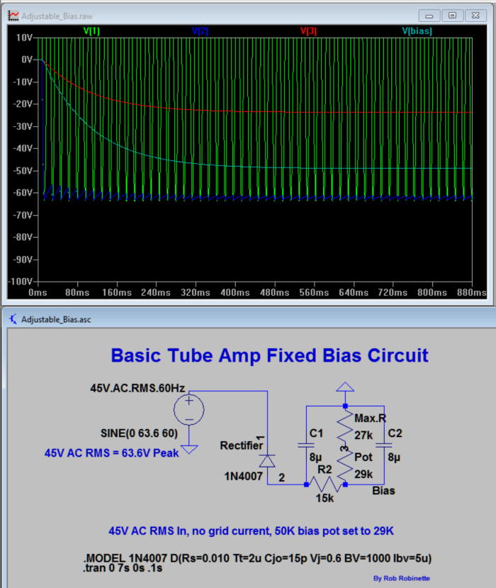
LTSpice model of the standard 5F6A bias circuit. Bias voltage is plotted in light blue, transformer voltage is green, diode output is dark blue and red is the junction of the pot (set a 29k) and 27k resistor (56k total resistance). The bias voltage stabilized at -49v.
Adjustable Balanced Bias With Balance Pot
This mod uses a bias adjust trim pot and a balance pot so you can adjust the bias and balance the bias between the power tubes. This allows you to use unmatched tubes but bias them evenly. You can even run a 6V6 and a 6L6 power tube together and bias each tube properly. You can also fatten up the clean and overdrive tone by intentionally mismatching the two tubes' bias which increases harmonic distortion. An increased bias mismatch can cause an increase in hum so keep an ear out for that if you dial up an intentional mismatch.
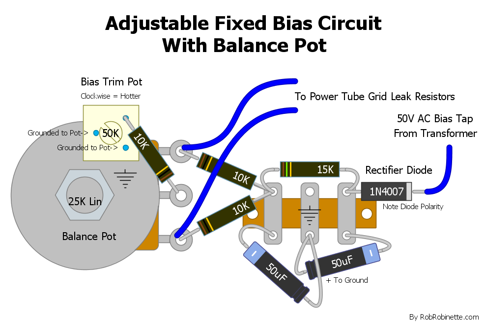
This is a complete bias power supply. The 50k Bias Trim Pot sets the bias and the Balance Pot balances the current between the two power tubes. Two of the 50k Balance Trim Pot's legs are soldered to the Balance Pot for ground (wiper & lower terminal). The Balance Pot case and the terminal strip's center terminal are grounded. Note the polarity of the rectifier diode and the 50uF filter caps. The two 50uF filter caps are connected + to ground and rated at 100 volts or higher. The trim pot's wiper connected to ground provides a failsafe in case the wiper fails. Reducing trim pot resistance moves the negative bias voltage closer to zero so bias current increases for a hotter bias. You must bias the amp after this mod.
Note you have to separate the two power tube grid leak resistors to give each one their own bias supply. One way to separate two power tube grid stopper resistors that share a turret is to de-solder them from the turret then use 20 to 24 gauge solid core wire (solid core so it will stay in place) to run from the bias pot's output terminal to the now empty turret. Put two wraps each around the turret for support (leave the wire insulation on for the wraps) and solder each resistor to a wire end.
Note: If your rectifier tube socket has "backup" diodes on the socket you must tap the high voltage for the bias circuit on the transformer side of the backup diodes.
I highly recommend this Bourns 50k multi-turn trim pot part # 3299Y-1-503LF. At 50k it will offer a wide range of adjustment and since it's a multi turn trim pot it is very precise too. Less pot resistance to ground = bias voltage closer to zero = hotter bias.

Adjustable Balanced Bias With Dual Bias Pots
This mod uses dual bias pots so you can set the bias of each power tube.
5F6A Adjustable Balanced Bias
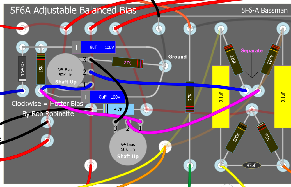
Note you have to separate the two 220k power tube grid leak resistors to give each one their own bias supply.
One way to separate two power tube grid stopper resistors that share a turret is to de-solder them from the turret then use 20 to 24 gauge solid core wire (solid core so it will stay in place) to run from the bias pots' center wipers to the now empty turret. Put two wraps each around the turret for support (leave the wire insulation on for the wraps) and solder each resistor to a wire end.
The 27k bias resistor sets the maximum hot bias. If at full clockwise pot movement (max hot bias) you still need to bias hotter then reduce the value of the 27k resistor--try 24k or 20k. If at full counter-clockwise pot movement (min cool bias) you need to bias cooler then increase the value of the 27k resistor to 30k or 36k. You must bias the amp after this mod.
High Voltage Tap Adjustable Bias for Center Tap PT
You can use this circuit that's loosely based on the Marshall JCM800 to create an adjustable bias tap without using a power transformer with a dedicated 50v bias tap.
This circuit is designed for use only with power transformers using a center tap and a conventional rectifier. See the next section below if your amp has a bridge rectifier.
You tap high voltage AC from the rectifier tube and create an adjustable bias circuit. This is a universal circuit that can be used on pretty much any amp. Turning the bias pot clockwise will make the bias hotter (more plate current). A 50k linear pot or trim pot offers lots of adjustment range so this circuit can bias everything from the 6V6GT to KT88's and it isn't picky about the AC input voltage level.
If you end up needing a cooler bias than the circuit provides you can reduce the 220k resistor (try 180k or 150k) for more room on the cool side of the adjustment range. If you need more room on the hot side then increase the 220k resistor to 240k or 270k.
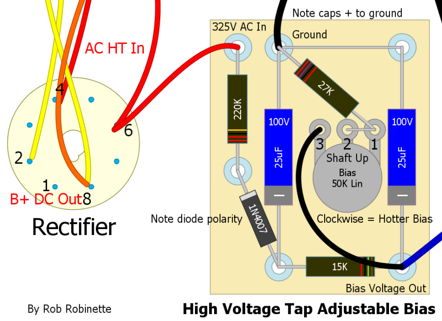
Note the two 25uF 100 volt filter caps have their + terminals connected to ground because the circuit is dealing with negative voltage. Be sure and get the 1N4007 diode's polarity right with its stripe facing the power transformer. The bias pot is shown shaft up. All resistors are 1/2 watt rated. The black wire at the top goes to ground. The blue wire at bottom right carries bias voltage out to the power tube grid leak resistors.
The two filter caps can be anything from 10uF to 50uF, and 100 volts and up. For the bias pot you can use a normal type pot, a screwdriver slotted pot or a trim pot.
Note: If your tube rectifier socket has "backup" diodes on the socket you must tap the high voltage for the bias circuit on the transformer side of the backup diodes.
How It Works
High voltage AC from the power transformer enters the circuit at the 220k voltage dropping resistor. The diode acts as a half-wave inverter creating 60Hz pulsed negative voltage DC (simply turning the diode around would give you positive voltage). The pulsing negative DC is filtered by the two 25uF filter caps and 15k resistor. The caps and resistor form an RC (resistance capacitance) low pass filter to smooth the DC and remove the 60Hz ripple current. The bias pot and 27k resistor form a variable resistor that when combined with the 15k resistor create a variable voltage divider. Lowering the bias pot resistance sends more voltage to ground which moves the output DC bias voltage closer to 0 volts which allows more power tube bias current to flow making the bias hotter.
JCM800 Bias Circuit
My circuit increases the value of the two filter caps to reduce hum and reverses the value of the pot and resistor to increase the bias range to work with more amps and tube types.
High Voltage Tap Adjustable Bias for Bridge Rectifiers
You can use this circuit that's based on the Marshall JCM900 to create an adjustable bias tap without using a power transformer with a dedicated 50v bias tap. This circuit is designed for use with bridge rectifiers with no center tap. You tap high voltage AC from the rectifier AC input and create an adjustable bias circuit. This is a universal circuit that can be used on pretty much any amp with a bridge rectifier. Turning the bias pot clockwise will make the bias hotter (more plate current). A 50k linear pot or trim pot offers lots of adjustment range so this circuit can bias everything from the 6V6GT to KT88's and it isn't picky about the AC input voltage level.
If you end up needing a cooler bias than the circuit provides you can increase the 47k resistor (try 51k or 56k) for more room on the cool side of the adjustment range. If you need more room on the hot side then decrease the 47k resistor to 43k or 39k.
This circuit is designed for use only with bridge rectifiers (no power transformer center tap). See the section above if your amp has a center tapped power supply.
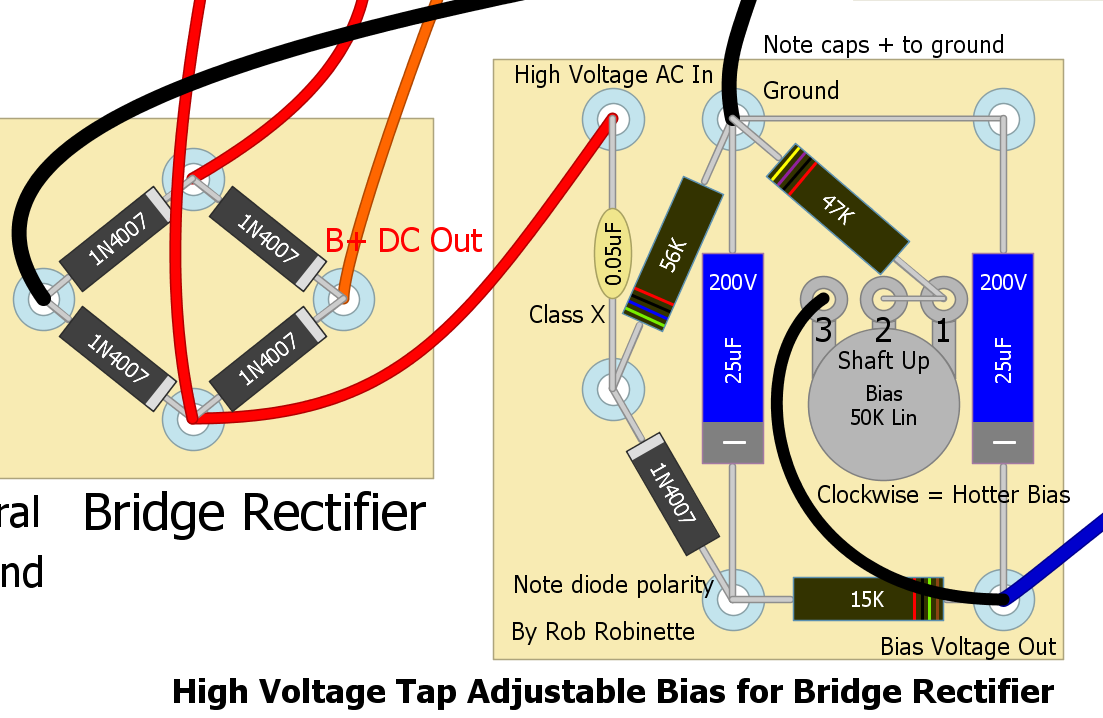
Note the .05uF capacitor must be rated as Class X. The two 25uF 200+ volt filter caps have their + terminals connected to ground because the circuit is dealing with negative voltage. Be sure and get the 1N4007 diode's polarity right with its stripe facing the rectifier. The bias pot is shown shaft up. All resistors are 1/2 watt rated. The black wire at the top goes to ground. The blue wire at bottom right carries bias voltage out to the power tube grid leak resistors.
This Vishay .05uF capacitor has a Class X safety rating meaning it is rated to be connected from 400V AC to ground and if it fails it will not short out. The two filter caps can be anything from 10uF to 50uF, and 100 volts and up. For the bias pot you can use a normal type pot, a screwdriver slotted pot or a trim pot.
How It Works
High voltage AC from the power transformer enters the circuit at the .05uF Class X capacitor (X rated for use across mains voltage). This cap forms a voltage divider with the 56k resistor to reduce the input AC voltage. The 56k resistor also supplies the capacitor recharge electrons from its ground connection.
The diode acts as a half-wave inverter creating 60Hz pulsed negative DC voltage (simply turning the diode around would give you positive voltage). The .05 cap, 56k resistor and diode form an electron one-way valve. Negative AC voltage passing through the cap pushes electrons against the 56k resistor and through the diode creating a negative DC voltage at the diode's output. Positive AC voltage from the cap tries to pull electrons through both the diode and resistor but the diode won't allow it so electrons are pulled through the 56k resistor to charge the cap. This is repeated every AC cycle.
The pulsing negative DC put out by the diode is filtered by the two 25uF filter caps and 15k resistor. The caps and resistor form an RC (resistance capacitance) low pass filter to smooth the DC and remove the 60Hz ripple current. The bias pot and 47k resistor form a variable resistor that when combined with the 15k resistor create a variable voltage divider. Lowering the bias pot resistance sends more voltage to ground which moves the output DC bias voltage closer to 0 volts which allows more power tube bias current to flow making the bias hotter.
See the Marshall JCM900 schematic for a schematic view of this circuit. My circuit increases the value of the two filter caps to reduce hum and increases the value of the pot to increase the bias range to work with more amps and tube types.
See This to Measure and Adjust Your Amplifier's Bias.
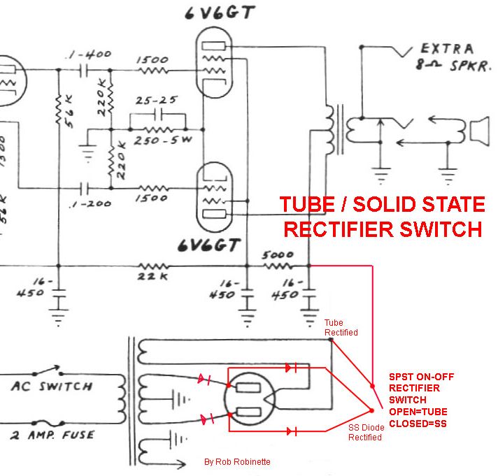
Tube / Solid State Rectifier Switch
This simple mod will give you the choice of normal tube rectification with it's inherent voltage sag or give you solid state rectification with its higher, stiffer voltage. Solid state rectification and its higher B+ voltage will make the amp a little punchier and modernize the tone slightly. The GZ34 tube rectifier only drops the voltage about 18 volts compared to solid state but you can use a tube rectifier with more voltage drop like the 5U4G with a 44 volt drop to emphasize the difference, but make sure your power transformer can supply 3 amps of 5 volt heater current (the GZ34 uses only 2 amps). The extra voltage drop of the 5U4G will lower all the amp's voltages, soften the tone and make the amp a little 'browner.' The extra rectifier voltage sag will affect the amp's dynamics and may enhance note 'bloom.' The solid state rectifier position works great with the 'JTM45' negative feedback mod and will help the tone sound more "modern Marshall".
If your amp is fixed bias and taps its bias voltage from the power transformer's high voltage secondary you must keep the bias tap BEFORE any diodes because the high voltage bias circuit must be fed AC voltage. If your amp is cathode biased or fixed biased with a separate power transformer bias supply wire then this mod will work without any modifications.
Rectifier Switch In a 5E3 Deluxe
Open switch = tube rectification, closed switch = solid state rectification. When the switch is closed the diodes' low voltage drop bypasses current around the tube rectifier.
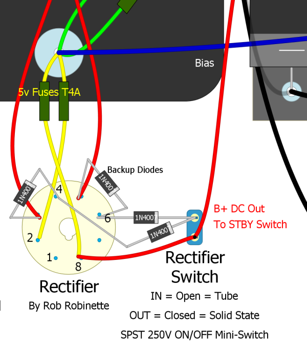
The 'Backup Diodes' mounted on the rectifier tube socket pull double duty. When using tube rectification they share the load with the tube rectifier and extend its life. They also protect the amp from a rectifier tube short. When solid state is selected with the Rectifier Switch both sets of diodes work together to directly supply the rectified B+ . The second pair shares the load and add redundancy by protecting from a failed, shorted diode.
You can also use an ON-ON SPDT 250V mini switch. Connect the B+ output wire to the center switch terminal. Connect the diode rectifiers to one of the other terminals and connect the wire from tube pin 8 to the third terminal.
Here's a chart from 300guitars.com showing the different rectifier voltage drops:
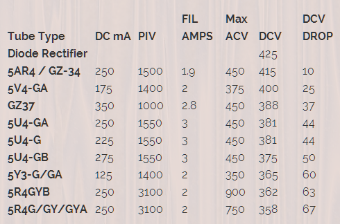
The 5Y3's current rating of only 125 milliamps would strangle a 5F6A but the 5R4 will work nicely. Note the 5 volt 3 amp heater current requirements for some of the tubes.
Add a Mid Tone Pot
In the standard Fender tone stack a 6.8k Mid resistor is used in amps without a Mid pot (usually a 10KA pot). You can simply replace that 6.8k resistor with a pot wired as a variable resistor. A 10KA Mid pot is Fender standard but a 25KA, 50KA or 100KA can be used to give the Mid tone control more authority. Turning a 100KA Mid pot up adds resistance to the tone stack ground which "removes" the entire tone stack for a flatter tone curve and less signal load so you also get more gain. Turning the 100KA Mid pot up high gives us a "tweed" type tone due to a flatter tone curve and more gain. Also, as you turn up the Mid control the bass and treble pots will have less effect.
My personal favorite Mid tone control is a 6.8k resistor in series with a 100KA Mid pot. This allows me to set the Mid control to minimum and get Fender "normal" 6.8k mid resistance. Turn it up and I transition from blackface to tweed tone.
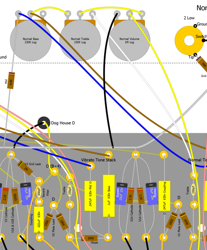
Typical Fender/Marshall/Vox Tone Stack

The 6.8k Mid resistor is at the bottom of the schematic. It serves as the entire tone stack's ground connection. Adding Mid resistance adds mid frequencies and reduces the tone stack load which adds gain. Disconnecting the Mid resistor will completely remove the tone stack from the amp circuit.
Amp With a 6.8k Mid Resistor and No Mid Pot
The 6.8k Mid resistor supplies the tone stack connection to ground. The bottom of the resistor is connected to the preamp ground bus bar.
Amp With a Mid Pot
The Mid pot simply replaces the 6.8k Mid resistor.
My Favorite Mid Control Setup

100KA Mid/Raw pot with a 6.8k Mid Minimum resistor allows rolling the pot down to minimum to get "normal" Fender 6.8k mid tone. Turn up the pot a little to add mids, turn it up a lot and you approach tweed tone with flat tone curve and more preamp gain. You can also use a 25KA or 50KA Mid pot for less max tweed. Note that if a Presence pot ground is connected to the Mid pot you will need to run the presence pot directly to ground--do not run its ground through the 6.8k Mid Minimum resistor.
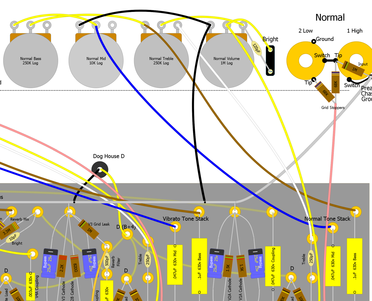
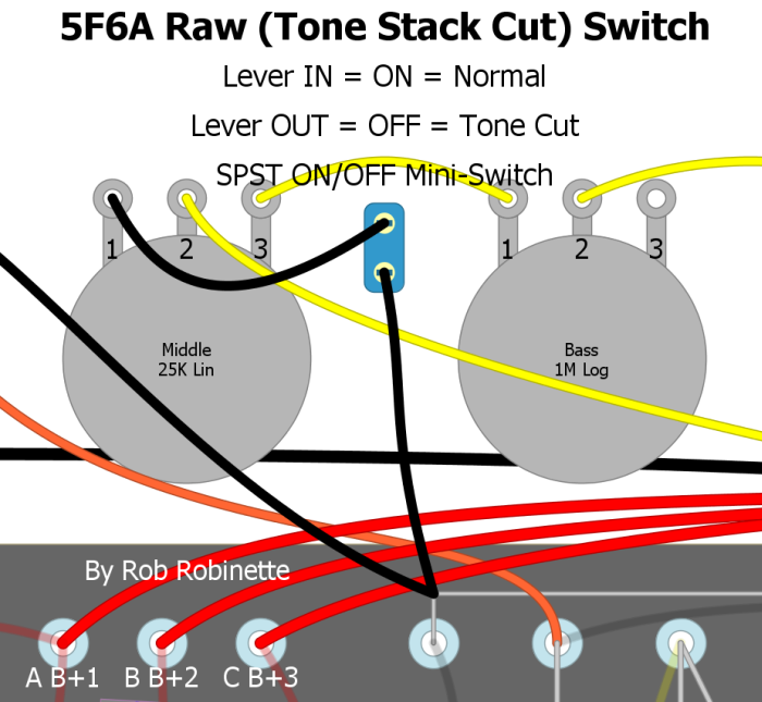
Raw (Tone Stack Bypass) Switch
This is a great mod for pretty much any amp with a TMB (treble mid bass) tone stack. Add an SPST ON/OFF mini-switch to the Middle tone pot's ground. No ground = no tone stack which gives you a very significant signal boost and pure "raw" unaltered tone. I find myself using this switch to instantly find a known, standard tone. It also works great with EQ pedals because it lets the pedal do all the tone shaping. I was surprised by how much of a signal boost I got with this switch engaged, even with all three tone controls at max. This is a simple and very worthwhile mod for any amp with a standard tone stack.
If you feel the jump in gain is too much or the raw tone is too wooly you can reduce the raw boost effect by putting a resistor between the two raw switch terminals so when the switch opens for "raw tone" some tone stack current can still flow. Opening the raw switch will add the resistor value to the tone stack mid cap value. When the raw switch is in the normal, closed position the raw switch resistor is bypassed.
You can also combine the Raw Switch with the Raw Control pot (next mod below) so you can fine tune the tone you get with this switch. I placed my Raw mini-switch between the Middle and Bass pots.
Raw Switch On and Off
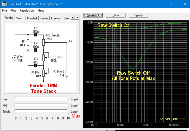
You can see how the mid scoop is flattened and what a huge boost in signal you get with the Raw Switch On (tone stack ground disconnected) even with all three tone pots at max. Chart is from the Duncan Tone Stack Calculator.
Be sure and take a close look at the presence pot ground wire. If it is connected to the mid pot you will need to give the presence pot its own connection to ground.
Remove the tone stack's ground and you completely bypass the tone stack.

5F6A tone stack and Raw Control location.
I had one modder get an oscillation when he bypassed his tone stack with a raw switch. The extra gain from removing the lossy tone stack was enough to cause a downstream gain stage to freak out. He solved the problem by placing a 100k resistor across the switch terminals. The resistor reduces the gain jump when the switch is opened.
Raw Control
The "Raw Control" is a pot that controls the amount of tone stack bypass. You can go from standard max tone stack to no tone stack or "raw" unshaped signal. A 100KA (audio or log) pot is wired as a variable resistor in the tone stack ground wire coming out of the Mid tone pot terminal 1. As you turn up the Raw Control more tone stack is bypassed and volume increases. More Raw pot resistance will give you more "raw" and less tone stack.

Tone stack's ground wire from Middle Tone pot terminal 1 is run to 100KA pot then to ground. The layout shows a 250KA pot but I recommend a 100KA pot.
You can easily combine the Raw Switch and Raw Control by placing the Raw Switch between the Raw Control pot and the ground or between the Raw Control and Middle tone pot.
You can also get the same effect by simply replacing the Mid tone pot with a 100KA audio (log) pot. The pot's extra resistance will allow you to dial out most of the tone stack. With the new Mid control set to 1 you get lots of headroom, Twin-Reverb like clean. At about 3-4 you get the normal mid voicing. And at 10 you get full tweed - meaning the tone stack is almost completely eliminated from the amp circuit so you get a nice signal boost. This is a very simple remove-and-replace mod that is very worthwhile.
Be sure and take a close look at the presence pot ground wire. If it is connected to the mid pot you will need to give the presence pot its own connection to ground as shown in the 5F6-A layout above.
Bass Tone Control
This is a simple Bass Tone Control. As you turn the pot down it removes bass frequencies. It uses a very small mica cap in line with the audio signal which strips out low frequencies. A 1MRA (1 megaohm reverse audio or anti-log) pot wired as a variable resistor gives you a variable cap bypass. As you turn the Bass pot up (clockwise) less signal goes through the cap and less bass is cut. At full up (clockwise pot rotation) the cap is fully bypassed so all frequencies pass around the cap and normal, full frequency amp tone is passed. Run the control at full up (full clockwise) for normal, full frequency tone because at full bypass the Bass Tone Control circuit disappears.
The corner frequency of the Bass Tone Control changes with signal impedance but the 500pF cap will work at most places in the amp circuit. A high impedance signal will pass lower frequencies through the cut cap so if you need more control authority then reduce the cap size to 250 or even 100pF.
The Bass Tone Control circuit cannot be used as a coupling cap (blocking cap) because the pot will allow DC to pass. The Bass Tone Control must be placed downstream of a coupling cap to keep DC out of the pot.
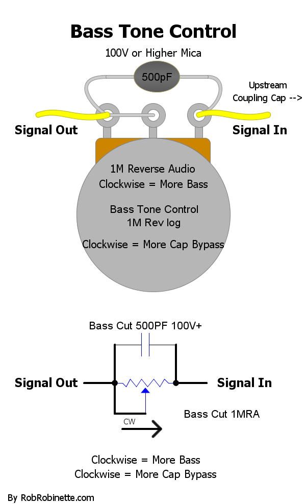
The Bass Tone Control circuit is a small value cap with a variable bypass. More bypass gives you more bass, fully bypassed (full clockwise rotation) gives you a normal, full frequency signal. The mica cap should be rated for 100v or higher. Download the pdf here and the DIYLC file here.
Bass Cut Control
This control is the opposite of the above Bass Tone Control. As you turn the pot up it reduces bass. It uses the same very small mica cap in line with the signal which strips out low frequencies. A 1MA pot wired as a variable resistor gives you a variable cap bypass. As you turn the Bass Cut pot up (clockwise) more signal goes through the cap and more bass is cut. At full down (counter-clockwise pot rotation) the cap is fully bypassed so all frequencies pass around the cap and normal, full frequency amp tone is passed. Run the control at full down (full counter-clockwise) for normal, full frequency tone because at full bypass the Bass Cut circuit disappears.
The corner frequency of the Bass Cut Control changes with signal impedance but the 500pF cap will work at most places in the amp circuit. A high impedance signal will pass lower frequencies through the cut cap so if you need more control authority then reduce the cap size to 250 or even 100pF.
The Bass Cut Control circuit cannot be used as a coupling cap (blocking cap) because the pot will allow DC to pass. The Bass Cut Control must be placed downstream of a coupling cap to keep DC out of the pot.
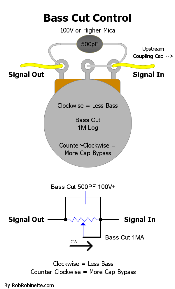
The Bass Cut Control circuit is a small value cap with a variable bypass. Less bypass gives you less bass, fully bypassed (full counter-clockwise rotation) gives you a normal, full frequency signal. The mica cap should be rated for 100v or higher. Download the pdf here and the DIYLC file here.
Lar-Mar/Trainwreck Type-2 & Type-3 Master Volume
If you are building a new amp then I recommend installing the Lar-Mar/Trainwreck Type-2 master volume. It is much more difficult to add this type of master volume to an existing amp so for modding an amp I recommend the Type-3 master volume below.
Lar-Mar/Type-2 Master Volume
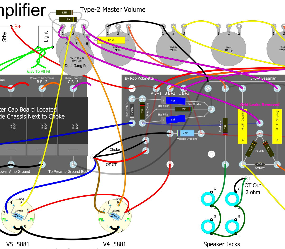
A dual gang 250KA pot (one shaft turns both pots, audio or log taper) replaces the two 220k power tube grid leak resistors. This is the most transparent of all the master volume types. The 1.8M resistors on the Master Volume pot reduce the max pot resistance to 220k and add a failsafe path for bias voltage. For fixed bias amps without a bias filter cap on the bias output side of the bias circuit you will need to add a Master Volume AC Ground cap so the amp will be silent at the minimum master volume setting. The cap is not required if you don't care if the amp is completely silent when the master volume is set to minimum nor in amps with cathode biased power tubes. The 5F6A Bassman circuit shown above has fixed bias and does have a bias filter cap at its output (lower 8uF Bias Filter cap) so the MV AC Ground cap is not needed. If you install an MV AC Ground cap it must be connected + to ground because it deals with negative bias voltage. The MV AC Ground cap will also add additional bias hum cancelation.
Trainwreck Type-3 Master Volume
There are many master volume options but the Trainwreck Type-3 is very easy to install and works as well as any other master volume I've tried in any of my amps. This master volume controls the signal level feeding the power tubes so you can use it for lower volume distortion and to control the balance between preamp and power tube distortion. It works by mixing the two phase inverter output streams together and they cancel each other out. Less resistance = more signal mix and less output volume.
For the Type-3 master volume you simply add a 1 mega ohm audio (log) pot and two wires. It's easy to temporarily alligator clip the pot into the circuit to give it a try. When the Master Volume pot is set to max the master volume circuit virtually disappears and will not color the amp's tone.
You can place your master volume pot anywhere but you may have to use shielded wire to prevent noise or oscillation. I use RG-174 when I need shielded coax in an amp. Only ground one end of any coax cable in an amp, preferably the signal input end, to keep from forming a ground loop. If you keep the wire runs relatively short and away from the power transformer end of the amp you should be OK without using shielded coax.
Simple But Effective Trainwreck Type 3 Post Phase Inverter Master Volume (PPIMV)
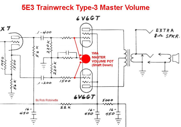
Add a 1 megaohm audio (log) pot and two wires and you've got an effective post phase inverter Master Volume. As you turn the Master Volume pot down (counterclockwise, pot is shown shaft down) more of the opposite phase signals from the phase inverter are mixed together which cancels the signal out. I did this mod to my 5F6A Bassman and it works great.
If you are anal you can completely eliminate the Type-3 from the amp circuit by adding a switch to disconnect the circuit. Use a 250KA pot with a push-pull DPDT switch and wire one leg of the master volume through the switch so when the master volume knob is down the circuit is completely disconnected. Pull the knob up to activate the master volume. A 250KA pot will give you a better volume sweep than a 1MA and since we can disconnect the MV we don't have to worry about the 250KA pot affecting the amp tone.
To do this you would run the wire from the #2 (center) pot terminal to the upper left DPDT switch terminal, then run a wire from the middle left DPDT switch terminal to the circuit board's right 220k power tube grid leak resistor. The wire from the #1 (left) pot terminal would be wired as normal to the left 220k resistor (see layout below).
Type-3 With MV ON/OFF Push-Pull Pot
Master Volume knob Down = no master volume at all, Up = master volume on. This diagram shows a 5E3 Deluxe but the push-pull switch wiring is the same.
Another option is to use a switch and resistor for your master volume instead of a pot. You simply replace the master volume pot with a resistor on a switch. One guy used a 5k 1/2 watt resistor which gave him his preferred "bedroom practice" output level. Switch OFF = no master volume at all, ON = bedroom volume.
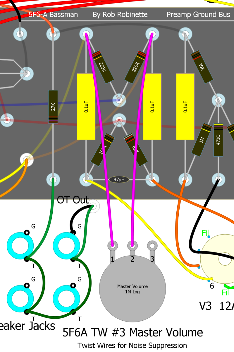
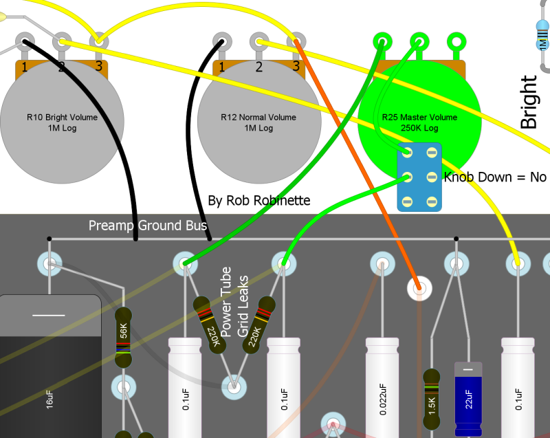
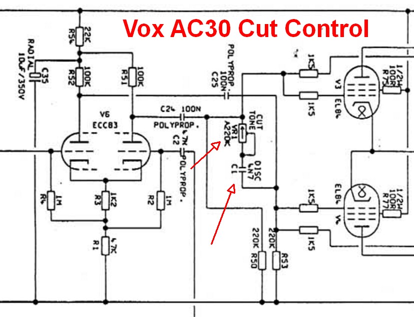
RobRob Master Volume + VOX Cut Control
I'm a big fan of the VOX style Cut Control because it's a great way to "trim the ice pick". Early in-the-circuit tone controls affect the substance of the overdrive tone. High freqs generate overdrive harmonics that fill in the top end. If you turn down a normal tone control to reduce ice-pick highs you'll kill all the harmonics too. A cut control allows you to trim off very high ice pick highs without removing all the high frequency overdrive harmonics. All high gain amps should have a late-in-the-circuit tone control for this reason. You can just leave the cut control on full high and you have a normal amp circuit.
The VOX Cut Control connects the two power tube grids with a 220k audio pot and 4.7nF (.0047uF) capacitor to allow variable high end cut. In a push-pull amp the guitar audio signals on the two power tube grids are 180 degrees out of phase with one another so mixing them together nullifies the signal, kind of like mixing matter and antimatter. The capacitor limits the effect to high frequencies but if you jumper around the cap the pot becomes a Trainwreck Type-3 master volume.
I like this very late tone tweak because it pairs well with an early tone control or tone stack. Use the early tone control (or guitar tone control) to get the overdrive tone and substance you want then use the Cut Control to fine tune the tone and trim ice pick. The Cut Control affects only the power tubes.
Wire the cut pot as a variable resistor so that as you turn the knob up (clockwise) resistance increases. Up = more resistance = brighter tone. Connect the Cut Control to the two phase inverter outputs between the coupling caps and power tube grid stopper resistors (see schematic below).
220KA or 250KA pot (audio pot wired as variable resistor) and .0047uF 200v cap connect the two phase inverter outputs between the coupling caps and grid stopper resistors.
Cut Control on 5F6A Bassman
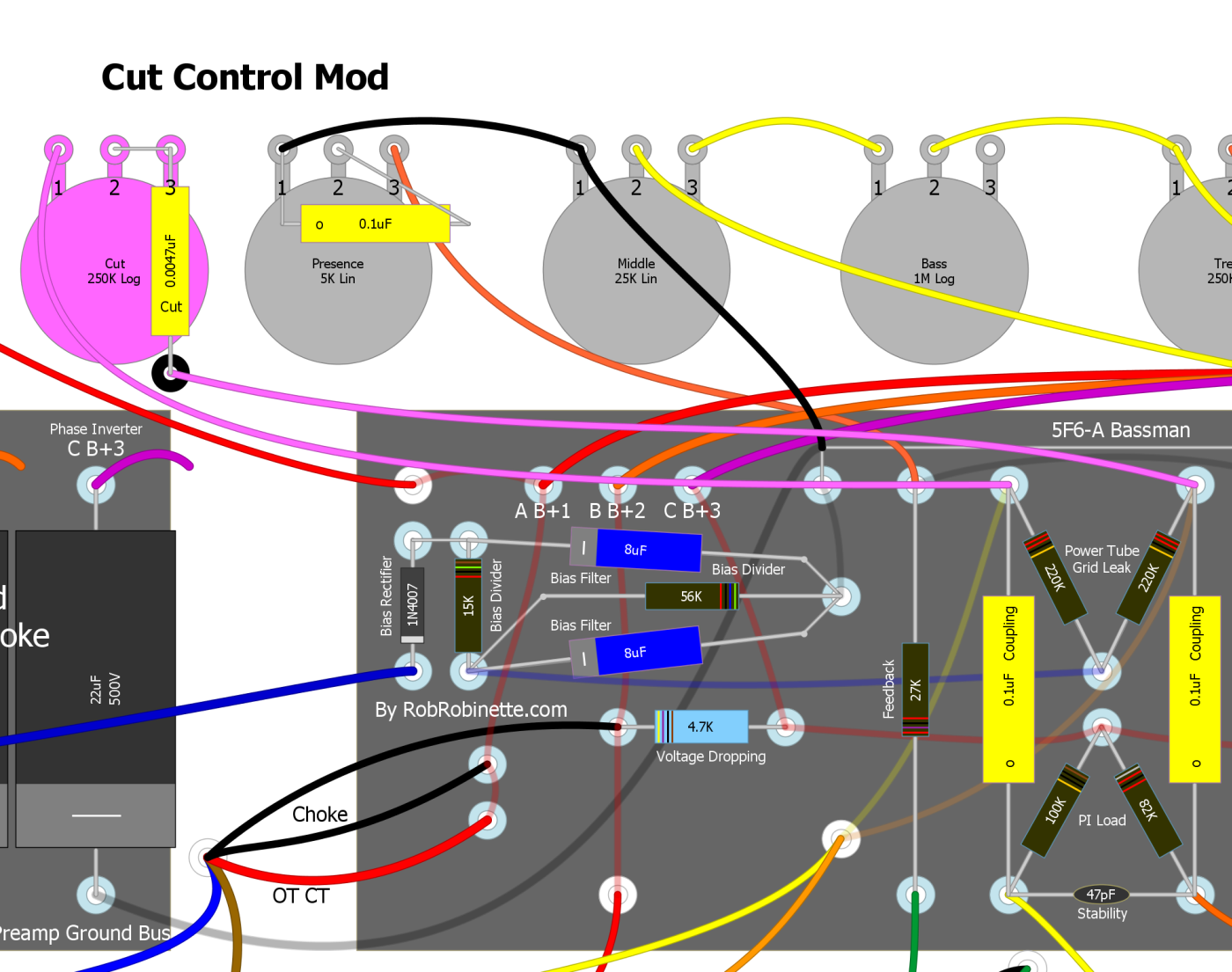
The .0047uF Cut Cap can be supported by a non-grounded terminal strip.
RobRob Master Volume + Cut Control Push-Pull Pot Mod
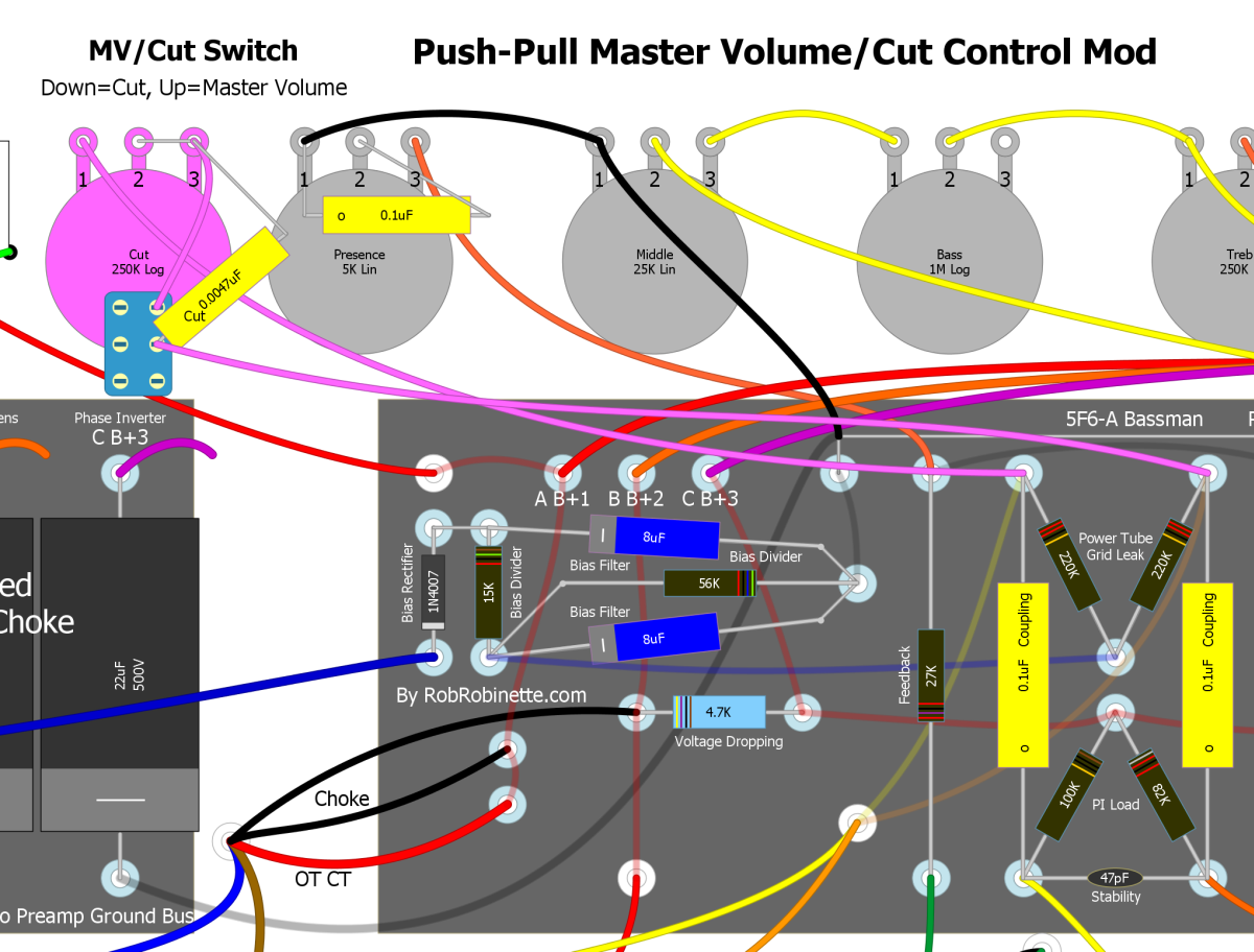
Use a 250KA push-pull pot and you can push the pot down for Cut Control or pull it up for Master Volume. Connect the cut capacitor from pot terminal #3 to the middle switch terminal.
Standby/Mute Switch
This is a simple mute switch. When the SPST switch is closed the two power tube grids are connected together which kills all signal before it enters the power tubes. I prefer this Mute circuit over the preamp mute in the following section because it kills signal late in the circuit in the power amp.
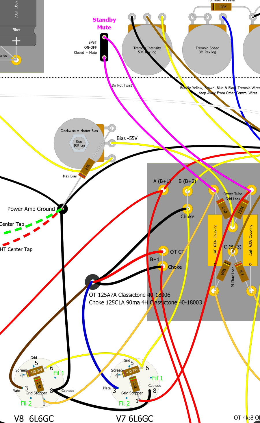
The Mute switch connects the power tube grids which kills all signal entering the power tubes.
Mute Switch
This is another simple way to add a Mute switch. An On-Off (SPST) switch grounds a preamp stage grid to silence the amp. There is no switch pop because the tube's grid leak resistor or volume pot act as switch "no pop" bypass resistors. Connect the switch to a preamp stage grid that all channels use so it will silence all channels. You cannot connect a ground switch like this to a phase inverter or cathode follower because their grids usually have DC voltage on them. If you are not sure about grid voltage you can carefully measure for DC voltage on the grid pin. In 12A*7 tubes pins 2 and 7 are the grids.
Mute Switch
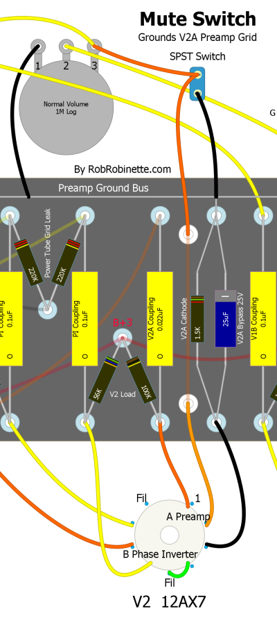
Switch down = normal, up = mute by closing the switch and grounding the preamp tube grid with all guitar audio going to ground. Simply insert the switch into a wire that connects to a preamp tube grid. Connect the other switch terminal to a ground (shown using a 5E3 Deluxe preamp ground bus above).
Power Tube Plate-to-Plate High Cut Control
This is an alternative to the VOX style Cut Control but I prefer the Vox Cut shown above. This High Cut Control is another way to "trim the ice pick". Early in-the-circuit tone controls affect the substance of the overdrive tone. High freqs generate overdrive harmonics that fill in the top end. If you turn down a normal (early-in-the-circuit) tone control to reduce ice-pick highs you'll kill all the harmonics too. A cut control allows you to trim off very high ice pick highs without removing all the high frequency overdrive harmonics. All high gain amps should have early and late tone controls for this reason. You can just leave the cut control on full high and you have a normal amp circuit.
The early Fender Model 26 Deluxe used a power tube plate-to-plate High Cut Control. Wire the cut pot as a variable resistor so that as you turn the knob up (clockwise) resistance increases. Up = more resistance = brighter tone.
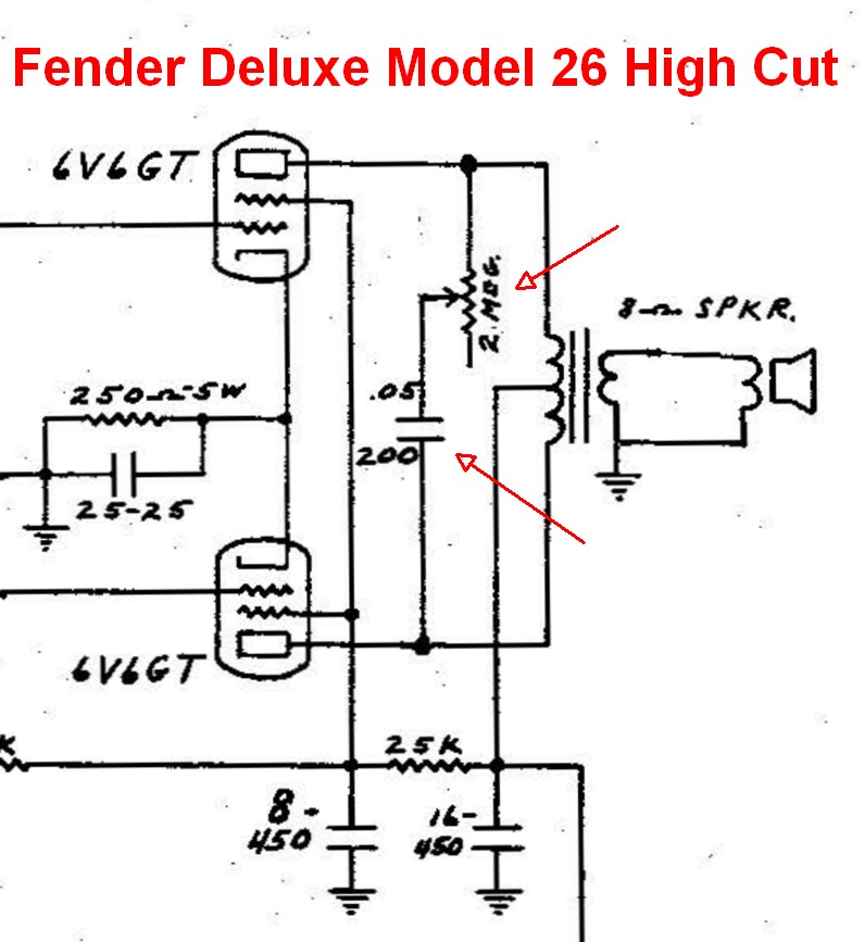
A 2 Meg audio pot and .047uF 400v cap (or higher voltage rating, 200v is too small for many amps) connect the power tube plates to remove high frequencies very late in the amplifier circuit.
Pre Phase Inverter Master Volume
For an amp with a cathodyne phase inverter like the 5E3 Deluxe or Princeton Reverb you can put a Master Volume before or after the phase inverter with good effect because the cathodyne phase inverter puts out approximately unity gain (no actual gain) which means it doesn't amplify the signal so the Master Volume can go before or after it. Placing the Master Volume before a cathodyne phase inverter (PRE Phase Inverter Master Volume) will allow you to control the amount of the cathodyne inverter's infamous overdrive 'double frequency' distortion at high volume levels or when using pedals that boost the input signal. Preventing the phase inverter from going into frequency doubling distortion can result in a much sweeter, tastier overdrive tone. Phase inverter double frequency blocking distortion is the reason why high gain modifications to cathodyne phase inverter amps are not popular. With a PRE Phase Inverter Master Volume you can easily dial in how much phase inverter distortion gets through to the power tubes. If you want to drive your amp hard with hot pickups or effects then the Pre Phase Inverter Master Volume will serve you well. It will make an amp with a cathodyne phase inverter much more pedal friendly because the phase inverter distortion can make a mess of reverb, delay and boost effects.
PRE PI Master Volume Schematic
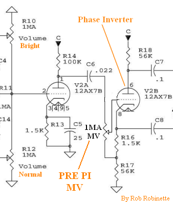
You simply replace the phase inverter's 1M grid leak resistor with a 1MA pot. Although there's DC voltage on the pot there's only 1.5 volts across the pot so normally the pot isn't scratchy.
Depending upon where you put your master volume pot you may have to use shielded cable to prevent noise or oscillation. You definitely need to use shielded wire if you put the master volume in place of the standby switch due to the noisy AC in that end of the chassis. The longer the wire run the more benefit from using shielded cable. I usually use RG-174 when I need shielded coax wire in an amp but multi-conductor shielded microphone style wire allows you to use one cable to carry the signal to and from the pot. Only ground one end of any coax cable in an amp, preferably the signal input end, to keep from forming a ground loop. If you keep your wire runs short and away from the power transformer end of the chassis you'll probably be fine with non-shielded wire.
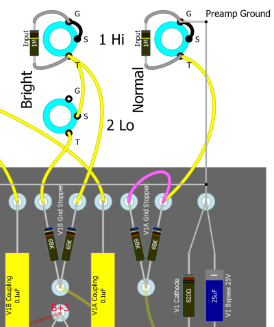
Removing one of the 'Lo' input jacks can make room for a master volume pot and you won't have to drill a new hole in the chassis. The 'Lo' jacks simply dump half the guitar signal to ground and you can do the same thing using your guitar volume control. I recommend you remove the Normal Lo jack (see layout below). Just clip the wire that runs from the Lo jack to the 68k resistor on the circuit board. Clip it at the jack end and solder it to the top of the Normal HI jack's 68k resistor. Connecting it this way will keep the Hi jack's grid stopper resistance at 34k (68K parallel).
Remove Normal Lo Jack
You could also use the second speaker jack hole for a master volume pot. Another option is placing the pot between the preamp tubes.
PRE Phase Inverter Master Volume
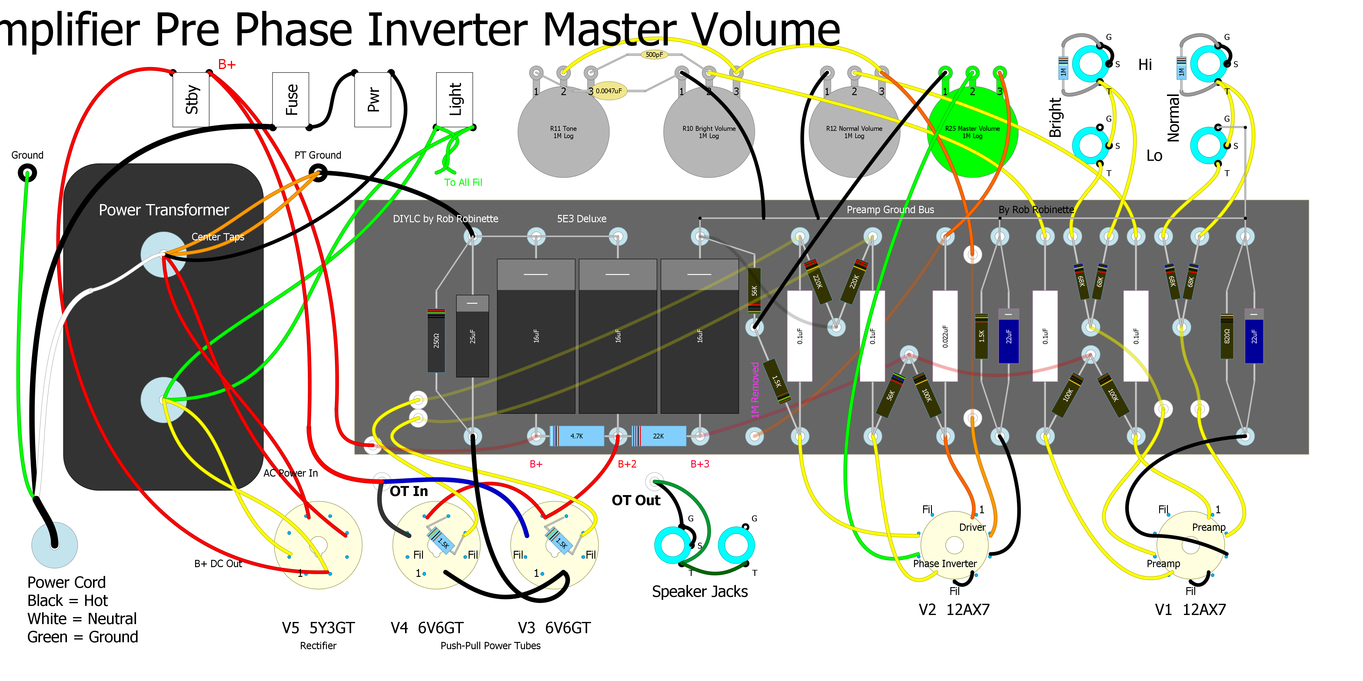
The PRE Phase Inverter Master Volume requires only a standard 1 megaohm audio (log) pot. Running the long wire from the Master Volume pin 2 to the tube socket under the circuit board can minimize noise by keeping the wire close to the metal chassis. Don't forget to clip or remove the 1M grid leak resistor (in pink at far left in layout above)
The PRE Phase Inverter Master Volume is my recommended master volume modification for amps with cathodyne phase inverters. The mod simply replaces the phase inverter's 1M grid leak resistor with a 1M log or audio pot. With the Master Volume full up the circuit is completely normal--it's as if the MV isn't there so it won't change your amp until you dial down the volume. It also allows you to dial out nasty 'double frequency' phase inverter blocking distortion, control the balance between preamp and power tube distortion and of course practice with dirt at lower volume--especially when paired with a boost pedal.
Doing the Mod
Start by checking the voltage at the first filter capacitor to ensure it's below 30V. If it's higher than that drain the caps.
Next determine the location of your master volume pot. Solder the lead wires to the pot before installation. Install the pot.
Remove the wire that runs from the original grid leak resistor to phase inverter's grid. You can just clip it at the resistor but you should de-solder it from the tube socket.
Connect the pot's three wires as shown in the above layout.
Be sure and try the Master Volume dialed down about 1/8 of a turn so you can hear your overdrive tone with excess phase inverter distortion dialed out. Same goes for reverb and delay effects.
PRE PI Master Volume With Volume Between Preamp Tubes
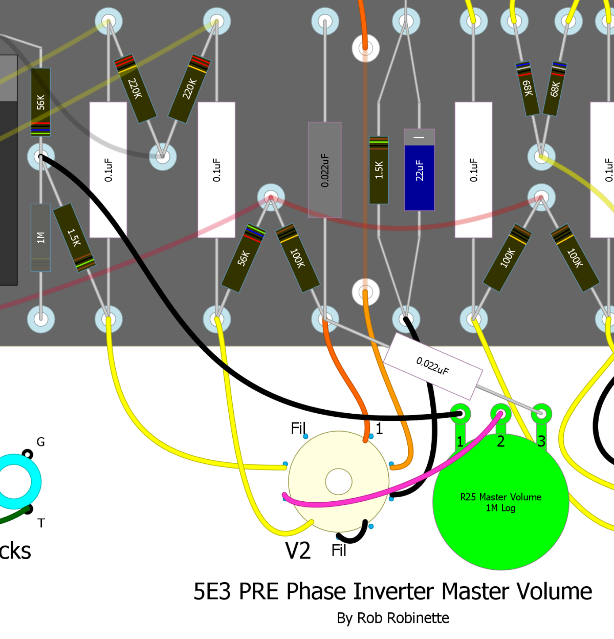
This is what I ended up doing on my 5E3 because I have a 'High Gain Cascade Channel' mini switch between the input jacks and the volume knob. This layout makes for very short wire runs. The 0.022uF capacitor was clipped at the top and bent down to connect to the Master Volume pot pin 3.
Master Volume pot placed between V1 and V2.
I like to leave the Master Volume turned down a little even when I want full volume because it adds some phase inverter grid stopper resistance which eliminates nasty sounding phase inverter blocking 'double frequency' distortion.
One Wire Cascade Mod
This is how the Old School converted their JTM45 (Marshall Bassman copy) into a high gain rock machine. It's a simple and easily reversible mod that sends the Normal channel output into the Bright channel's input for an extra gain stage. I also suggest changing the Bright channel's 270k mixing resistor to a 470k to help the V2A gain stage handle overdrive from the previous two gain stages. Another option to consider is changing the Normal channel's .02uF coupling cap to a .0047uF (400v or higher) to reduce some bass to tighten up the overdrive tone. The Normal channel coupling cap is the rightmost .02uF cap on the layout below. The Normal Volume control will function as a first stage "gain" control and the Bright Volume will function as the second stage volume.
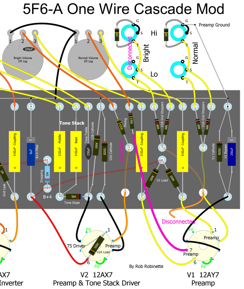
1. Disconnect the wire on V1 pin 7. 2. Disconnect the bottom of the Normal channel 270k mixing resistor. 3. Run a jumper wire from the output of the Normal Channel's 270k mixing resistor to V1 pin 7. 4. Optionally replace the Bright channel's 270k mixing resistor with a 470k 1/2 watt resistor. The new resistor will function as the V2A preamp's grid stopper and help control the heavy overdrive caused by the cascade mod. Another option to consider is to replace the Normal channel .02uF coupling cap with a smaller .0047uF (400v or higher) cap to reduce some bass frequencies to tighten up the overdrive tone.
Preamp Local Negative Feedback
This mod is an extremely easy to add local negative feedback loop that can be used to tune the overdrive tone of any high gain preamp. If you do a cascade mod like the previous "One Wire" mod this little mod is worth a try. The feedback is negative because the plate is 180 degrees out of phase with the grid. The mod connects a preamp's second
, third or fourth gain stage plate back to its grid through a 22M to 44M resistor and .047uF (400v or higher) cap.
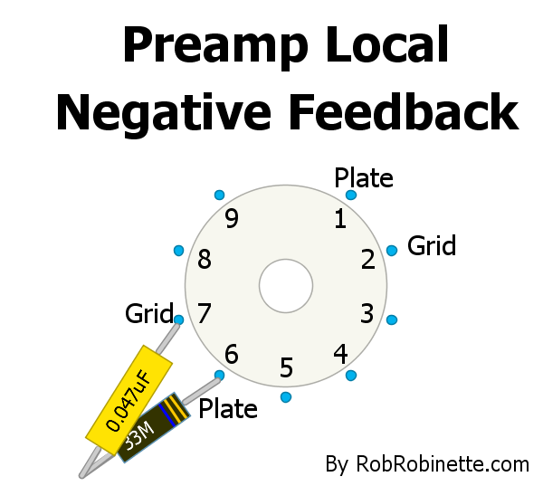
A 22M to 44M resistor and .047uF 400v+ cap connect the preamp grid and plate together to form a local negative feedback loop.
The mod can also be used on the "A" triode pins 1 and 2.Like most amplifier negative feedback loops this mod will reduce distortion, tighten the transition from clean to dirt and slightly reduce gain. At first blush I was going to recommend not using this mod on the first stage of amplification because if the cap fails as a short it could inject high voltage into the guitar circuitry but even if this does happen the large value feedback resistor will limit the current to 18 micro amps (.018 milliamp) or less so it's not a concern. This mod would be of relatively little use in the first gain stage anyway since it is rarely overdriven.
If this NFB loop tightens up the tone too much try a larger value resistor like a 44M. The larger the resistor the less negative feedback gets through to the grid. This is a pretty cool yet extremely simple circuit that should be experimented with in all high gain preamps.
The .047uF cap will give full spectrum NFB but the cap size can be decreased all the way
down to .0022uF (2.2nF) to restrict NFB to higher frequencies. Howard Dumble used a 33M resistor and .0022uF (2.2nF) cap on his "Tweedle Dee" modded 5E3 Deluxe phase inverter.3-Way Preamp Bias Switch
The normal value for a preamp cathode resistor is 1.5k which will typically give you symmetric clipping when it is overdriven. The Bassman's V2A second preamp stage uses a hot 820 ohm non-bypassed resistor which will gives hot asymmetric clipping. Many Marshall preamps use a cool 2.7k cathode resistor which leads to cool asymmetric clipping. This 3-Way Preamp Bias Switch will let you select Hot - Cool - Normal bias. In the diagrams below the switch is connected to the V2A cathode (pin 3) but this switch could also be used on V1A (pin 3) or V1B (pin 8) if you remove the jumper between V1's cathode pins (3 and 8) to separate the two cathodes. There is an overdrive tonal difference between all three switch positions.
The switch is a SPDT (single post dual throw) ON-OFF-ON mini switch with the cathode connected to the center switch terminal and the far end of the resistors grounded.
3-Way Preamp Bias Switch Without Bypass Caps
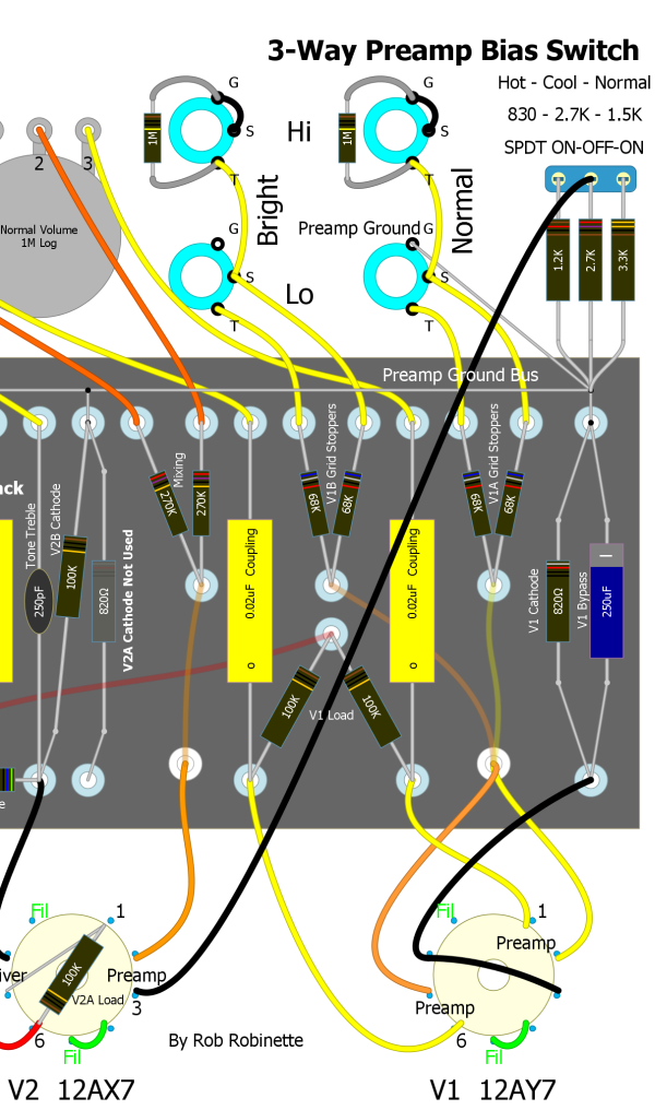
The V2A cathode resistor is switchable for Hot (830 ohms) - Cool (2.7k) - Normal (1.5k). Note the original 820 ohm resistor on the circuit board is no longer used (shown grayed out). When the switch is in the left position the 2.7k and 1.2k resistors are paralleled for 830 ohms. In the middle position only the 2.7k resistor is used. In the right position the 2.7k and 3.3k are paralleled for 1.5k.
3-Way Preamp Bias Switch With Always On 25uF Bypass Cap
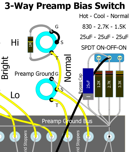
With a 25uF 25v bypass cap across the center 2.7k resistor the cathode is bypassed in all 3 positions. The bypass cap value is your choice and can range from 250uF (5F6A V1) to .68uF (Marshall high gain). Many Fender tweed and blackface amps used a 25uF bypass cap on the first preamp stage.
3-Way Preamp Bias Switch With Switchable Bypass Cap
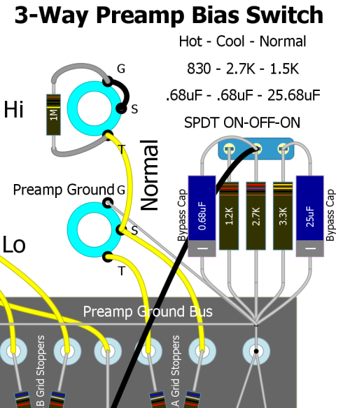
With a .68uF 25v bypass cap across the center 2.7k resistor and a 25uF 25v cap across the 3.3k resistor the cathode is bypassed at .68uF in the Hot and Cool positions and 25.68uF in the Normal position. High gain amps often use a hot or cool biased triode bypassed at .68uF. Fender tweed amps typically use a 1.5k bypass resistor and 25uF bypass cap.
Use 2 Input Jacks Instead of 4
This is how to drop the two "Low" jacks from any amp with the standard Bright/Normal/High/Low four input circuit:
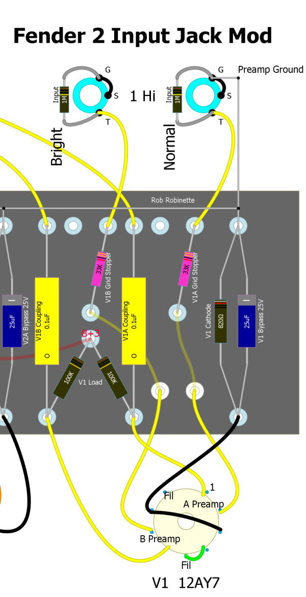
Note the grid stopper resistors (pink) were reduced from 64k to 33k because the Hi input jacks use both 64k grid stoppers in parallel for 32k of grid stop resistance.
Another option is instead of removing one 64k grid stopper resistor and changing out the other for a 33k as shown above, you simply run a jumper between the two 64k resistors so the signal goes through both for 32k of grid stop resistance.
Channel Jumper Switch
Since channel jumpering is so common among players this mod will let you leave your jumper cable at home and jumper the Bright and Normal channels with the pull of the Normal volume knob. You can plug your guitar into any jack and you will get a Hi jack-to-Hi jack jumper.
Just swap out the Normal Channel volume pot for a 1MA Push-Pull pot with DPDT switch (Bourns Model PDB183-GTR). If you prefer you can use a separate ON-ON DPDT switch to do the same thing. This switch will work on any amp that has Fender style four inputs (Bright/Normal/Hi/Lo).
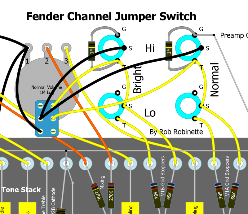
Note the wires between both Hi Jacks' ground and switch terminals have been cut.
With the Normal volume knob down the input jacks function normally with the jacks grounded when nothing is plugged in. Pull the Normal volume knob up and the two Hi jacks are jumpered together for a fatter tone. Your guitar signal will flow through both V1A and V1B preamp tubes in parallel which adds some texture and complexity to the tone. For more info on channel jumpering see this.
To install the switch first remove or cut both Hi jacks' wire that runs between their tip and switch terminals. Then remove the Normal volume pot and wire the three volume pot terminals normally. Wire the DPDT switch part of the pot as in the layout above and you're done.
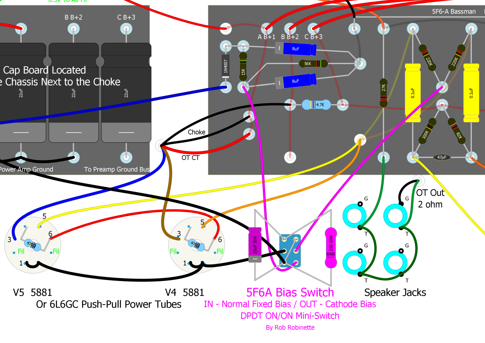
Fixed / Cathode Bias Switch
For amps that use a fixed bias circuit to bias the power tubes you can install a 2-way toggle switch to flip between normal fixed or cathode bias.
With this bias switch it's like having two different amps. You can run the amp in standard fixed bias mode or flip the switch to a more 'tubey', round, warm and compressed tone due to it's fluctuating cathode bias. Fixed bias tends to sound cleaner and punchier, especially the lows and it develops more power than cathode bias. There is a 'pop' when switching modes but it's not too loud and won't hurt anything.
The Fender 5E5 Pro used 6L6 tubes and a 250 ohm 10 watt cathode resistor so I recommend the same. The Pro came with a 25µF 25 volt cathode bypass capacitor which simply parallels the 250 ohm cathode resistor to boost gain. I recommend a 25µF 50 volt cap (rather than the Pro's 25 volt) because the voltage drop across the cathode resistor can easily exceed 25 volts.
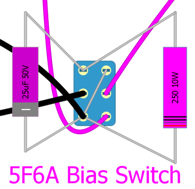
5F6A Bias Switch
Bias Switch Detail
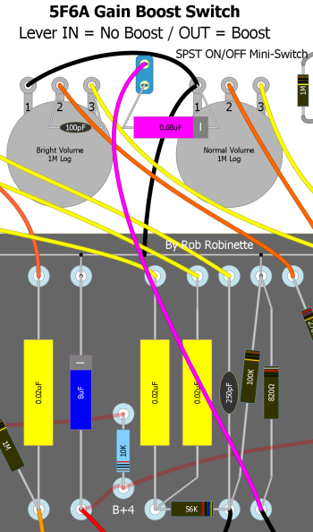
Gain Boost Switch
Add a switched 0.68uF (25v or higher) bypass cap to an unbypassed preamp cathode resistor to boost preamp gain. The added preamp gain allows for earlier breakup and more overdrive. The bypass cap will also modify the overdrive behavior of this triode and all the downstream tubes so this mod does more than add gain, it fundamentally alters the nature of the amp's overdrive tone.
I like to use this gain boost in conjunction with the Negative Feedback Switch in the Heavy Feedback position. The higher gain from the boost switch compliments the extra feedback.
I placed the SPST ON/OFF mini-switch on the front panel between the two volume pots. I mounted the bypass capacitor between the switch and the Normal Volume pot's ground.
Another option is to add a 50KL pot between the bypass cap and ground so you can vary the amount of bypass boost with the pot.
Switchable Plate Load Voltage Divider
This mod does the opposite of the above Gain Boost Switch in that it can cut a significant amount gain at the flip of a switch. This mod can make a high gain amplifier play better cleans.
The mod adds a switch bypassable 22k resistor that forms a voltage divider with the plate load resistor. With the switch closed and 22k resistor bypassed you get a normal 100k plate load resistor. Open the switch and the 22k 1 watt resistor is inserted and the resulting 100k & 22k voltage divider cuts the signal flowing downstream by 18%. Using a 50k instead of a 22k resistor would cut the signal by 33%. A 100k would drop 50%.

With the switch open the 100k plate load resistor and 22k resistor form a voltage divider to cut 18% of the signal coming off the V1B plate. Close the switch and the 22k resistor is bypassed so the divider goes away and you are left with a normal 100k plate load resistor.
Dumble Tweedle Dee Mods
Howard Dumble modified a Fender tweed amp which was nicknamed "Tweedle Dee". His Tweedle Dee mods reduce voltage sag, tighten up the 5E3's bottom end and sweeten the overdrive tone.
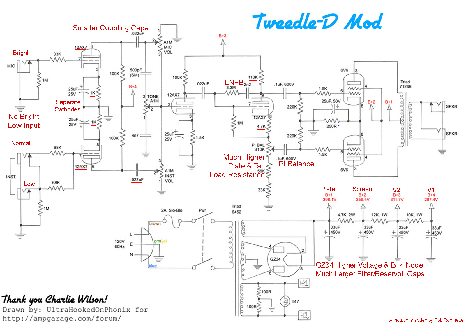
I have highlighted the differences between the Tweedle Dee and a standard 5E3 Deluxe. The phase inverter is the most important of the Tweedle Dee mods. Howard added local negative feedback between the plate & grid, increased the plate and tail load resistance from 56k to 110k, increased the cathode resistor from 1.5k to 4.7k and added the phase inverter balance pot.
Tweedle D Mods:
V1 12AX7 instead of 5E3's 12AY7 for more preamp gain
V1 cathodes separated
V1 cathode resistors 1k compared to 5E3 equivalent 1640 ohm for a slightly warmer V1 bias
V1 coupling caps reduced from .1uF to .022uF to trim excessive bass frequencies
Local negative feedback from phase inverter plate to grid
Helps the phase inverter deal with the added gain from the 12AX7 V1 by reducing nasty cathodyne phase inverter distortion, tightening the transition from clean to distortion and slightly reducing gain.
Phase Inverter plate and tail load resistance is increased from 56k to 110k
Phase Inverter Balance Control
The circuit allows control of the level of imbalance generated even order harmonic distortion. Add imbalance to fatten the clean tone or balance the phase inverter to clean up the overdrive tone.
A GZ34 rectifier tube is used in place of the 5E3's 5Y3 tube for higher voltage and less voltage sag
Filter/Reservoir caps are doubled in size from the 5E3's 16uF for less hum, less voltage sag and a tighter bottom end
An additional filter node is created to give V1 and V2 separate nodes and raise V2 plate voltage
Instead of one 22k voltage dropping resistor Howard used a 12k for B+3 and a 10k resistor to create B+4
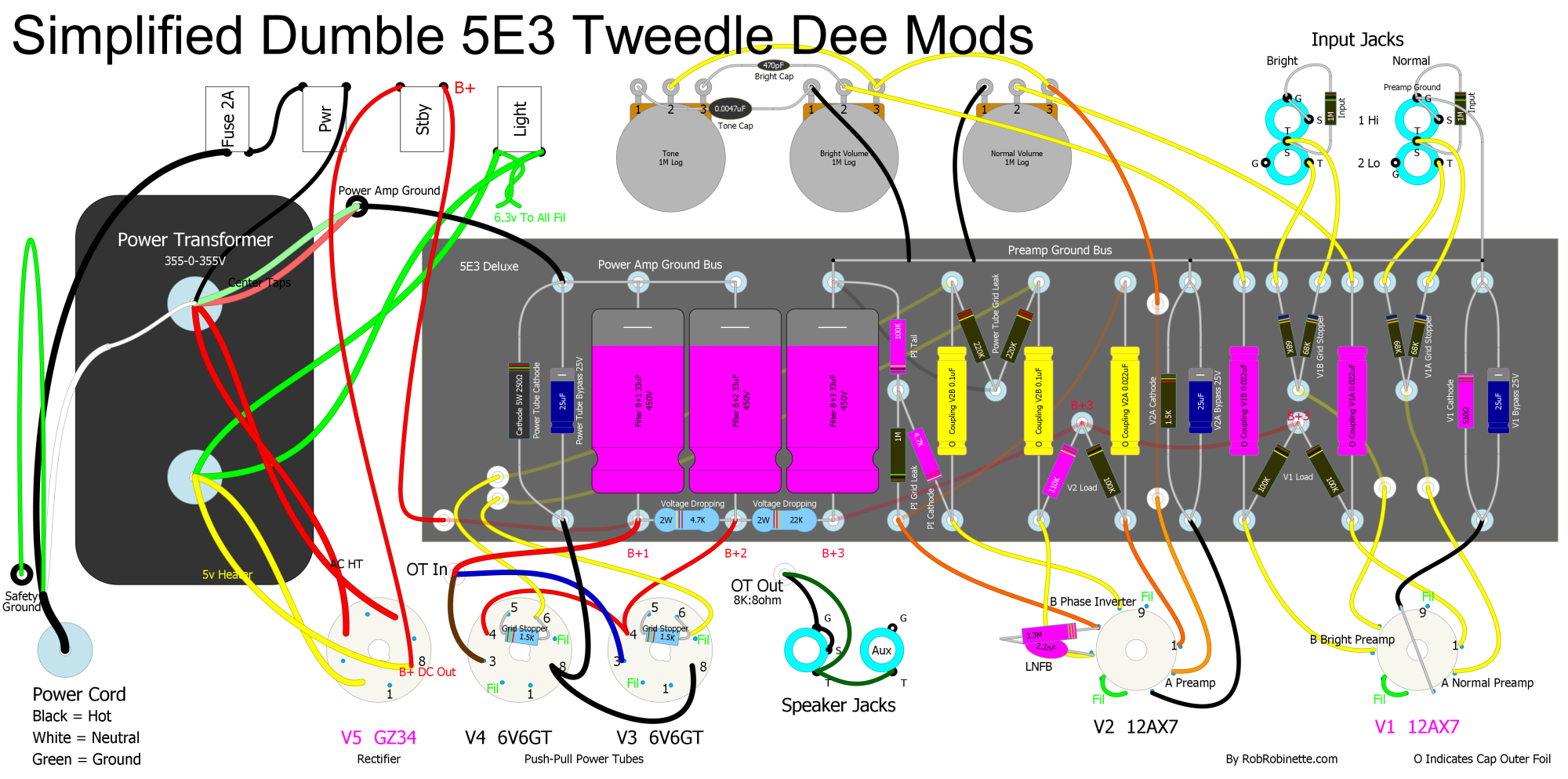
Tweedle Dee mods to a 5E3 Deluxe shown in magenta. The Phase Inverter Balance Control is deleted for simplicity. The V1 cathodes are not separated but the cathode resistor is reduced to 510 ohms to equal the Dumble separate 1k cathode resistors. The extra B+4 power node is deleted. These mods will get you very close to Tweedle Dee tone.
Add a VU Meter
This is a cool little addition that can make your amp stand out from the crowd. A VU meter displays voltage and connecting one to your speaker out will show your guitar signal. You can add a small, inconspicuous meter or go big.
You simply connect a 0-1v VU (voltage measuring) to the speaker jack. Connect the meter input to the speaker jack tip and add a resistor between the meter's ground terminal and ground. You can use a 10k pot to find the resistance needed to keep from banging the needle too hard at max volume. Once you find a pot setting that works just measure the pot resistance and replace the pot with a resistor. You could even keep the pot in place so you can tune the meter for low volume playing with full needle throw.

VU Meter On Speaker Out
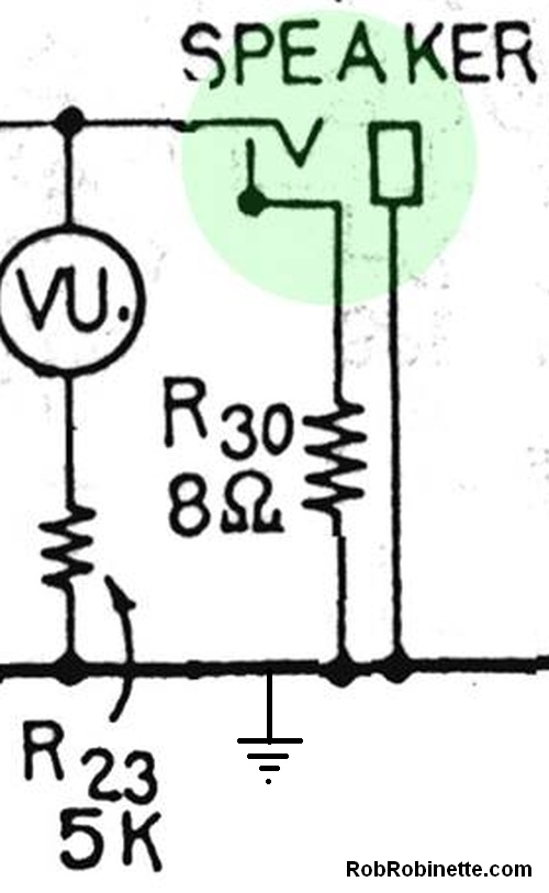
A 5k resistor works for this amp but the value will need to be adjusted for your amp.
EL34 Power Tube Compatibility Jumper
Using EL34, KT66, KT77 and KT88 power tubes can give your amp more of a "British" or "Marshall" tone. The EL34 is a true pentode while the rest of the tubes listed are beam tetrodes. True pentode tubes offer up more screen current when overdriven so they typically generate more power tube distortion. EL34's also need less input signal for maximum output so they tend to shift the balance of preamp to power amp distortion toward the power amp.
You need three conditions to safely run EL34 power tubes hard in an amp designed for 6L6 power tubes:
The power transformer must put out enough 6.3v heater current to satisfy the EL34's appetite for 1.6 amps per tube. For most amps your power transformer must be rated for at least 4 amps of 6.3v current. Many are only rated for 3 amps.
You will also need to install a jumper from pins 1 to 8 on both power tube sockets. This will tie the EL34's suppressor grid to the cathode. The 6L6 and KTxx tubes have internal jumpers that do this. Adding the jumper will not affect 6V6, 6L6 or other tubes. Many amps like Fender blackface and silverface amps use pin 1 to secure grid resistors. If your amp is using pin 1 you will have to relocate the resistor so you can tie pin 1 to pin 8.
Since the EL34 is a true pentode (not a beam tetrode like the 6V6, 5881 and 6L6) their screen grid picks up and flows more screen current so many EL34 amps use 1k 5 watt screen resistors instead of the the typical Fender 470 ohm 1 watt which is mounted directly on the power tube socket. You don't have to change the value of the screen resistor but you will most likely have to use a higher watt rated resistor. I left my 5F6A screen resistors at 470 ohms but increased them to 5 watts because increasing its ohm value will change the amp's clean and overdrive tone by altering the overdrive screen grid voltage drop. For more information on screen grid voltage and overdrive tone see Tube Guitar Amplifier Overdrive. If you are going to push the amp hard with EL34's on a regular basis I recommend upgrading the screen resistors to 470 ohms and 5 watts. Splitting the difference by using 750 ohm 5 watt screen resistors is also an option that should be considered if you plan to run 6L6 and EL34s.
Jumper Pins 1 & 8 together. The jumper does not affect 6L6 or any other tubes.
My 5F6A Head with JJ KT88 Power Tubes

My 5F6A head amp can use 6V6, 6L6, EL34, KT66, KT77 and KT88 power tubes. I ordered my head cab with about one extra inch in height to fit the taller KT88 tubes.
KT88's like more plate voltage than the 5881 and 6L6 so plugging in a solid state rectifier into the rectifier tube socket will raise the plate voltage by about 10 to 20 volts and put the big tubes closer to their sweet spot. One downside to doing this is it will also raise the voltage on the phase inverter and preamp tubes and the V2B cathode follower is already stressed by the stock voltage.
In my 5F6A the KT88's biased at -45.5 on the grid, 430 on the plates and 55 milliamps of plate current for 68.7% of their rated 35 watts of plate dissipation. That's with a JJ GZ34S rectifier tube. My primary Tung-Sol 5881's biased at -45.1 grid, 443 plate, 40.7ma for 69.3% of their rated 26 watts.
Voice a "Lead" Channel
This is another one of my favorite mods. In a typical two channel amp it's possible to voice one of the channels with a more modern, tight, Marshall "Lead" style tone. Remember, the only difference between most Normal and Bright channels is a bright cap on the bright volume pot which bypasses high freqs around the volume pot at low volume levels. At max volume there is no difference between the Normal and Bright channels so voicing one channel differently is a useful mod.
This mod will tighten up the overdrive tone and bottom end and make your amp more pedal friendly. Modifying only the first gain stage removes some of the guitar's low frequencies so the clean tone will be thinner but during overdrive later gain stages with larger coupling caps will allow low frequency intermodulation distortion harmonics to be passed through the amp for a subtle but thick low end. This will not happen in an amp with small coupling caps throughout. This "Lead" Channel mod will blow away your Marshall buddies.
You will also gain some clean headroom and maximum volume because low frequencies use up a lot of the amps power so removing very low frequencies allows more amplification of the remaining audio frequencies.
When evaluating this mod be sure and try a boost pedal to get the gain and distortion up--this is when this mod really shines.
Here's an excellent demo showing the difference between the 5E3 unmodified Bright channel and the "Lead Channel:" kdj 5E3 Lead Channel YouTube Demo
I used the Marshall 1987 Plexi as my roadmap for this "Lead" channel mod. The Plexi uses preamp component values to reduce low frequencies and boost high frequencies to offer a clean, tight, modern overdrive tone. The Lead channel will also be more pedal friendly than a normal Fender channel. This modification separates the V1 cathodes, increases the "Lead" channel's load resistor, cathode resistor, reduces its bypass capacitor and reduces the coupling capacitor. The unmodified channel gets a new 1.5k cathode resistor that's equivalent to the shared 820 ohm resistor. The original 250uF bypass capacitor is reused (yes, that's 250uF not 25).
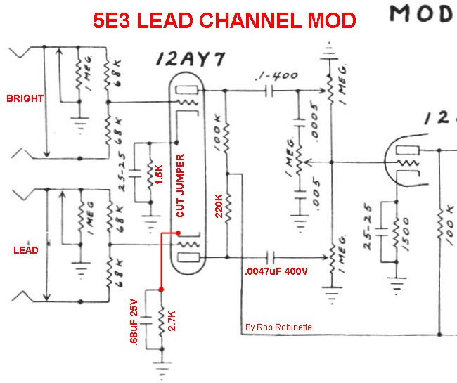
Schematic of the Lead Channel mod on the 5E3 Deluxe. The mod is exactly the same for many two channel amps.
The first step for this mod is to separate V1's cathodes so we can use different value bypass capacitors on each channel. We must also remove the cathode jumper from pins 3 to 8 on the V1 tube socket. The "Lead" channel gets a much smaller, Marshall size 0.68uF (50v or higher voltage) bypass capacitor to attenuate lower frequencies which will clean up and tighten the overdrive tone. This bypass capacitor size is rare but it does not need to be an electrolytic. The unmodified channel uses the original bypass cap so its tone will not change. You can modify either the Normal or Bright channel but I modified the Normal channel because I mostly use the Bright channel. I left the Bright channel as Leo Fender designed so I can still get the standard magical 5F6A tone when I need it.
If you choose to modify the Bright Channel I recommend you remove the bright cap to keep the overdrive tone from being too spikey.
Note that when we separate the cathode resistors we have to double their value to retain the same bias so V1 pin 8 (my unmodified channel) needs a 1.5K 1/2 watt cathode resistor (original was 820 ohms) to keep the same bias and tone. For the "Lead" channel (V1 pin 3) we move up to a 2.7k cathode resistor to cool the bias for Marshall style asymmetric clipping distortion. V1A's bias point is shifted toward cutoff so the guitar signal's negative lobe will get clipped at cutoff with a lower level input signal leading to earlier distortion onset. Negative lobe cutoff clipping will also occur earlier than the positive lobe (which gets clipped much later by saturation). With this asymmetric clipping the positive lobe carries the undistorted musical content while the negative lobe carries the distortion. Asymmetric distortion also adds even order harmonics and shifts the audio wave duty cycle away from 50% and makes the distortion sound more tubey and distinct from solid state distortion. Asymmetric distortion is often described as sounding "creamier" with less fizz than symmetric distortion.
Increasing the V1A load resistor from 100k to 220k will increase the channel's gain and make distortion in the V2A preamp more likely. I recommend using a 1 watt resistor to reduce resistor hiss.
We also want to reduce the value of the "Lead" channel coupling cap from 0.022uF to 0.0047uF (400v or higher) to again suppress unwanted bass frequencies but more importantly reduce bias excursion recovery time and therefore reduce preamp blocking distortion in the second preamp stage which will also smooth and sweeten the overdrive tone. Note that 0.0047uF = 4.7nF (nano Farad). If you don't want to deal with splitting the V1 cathodes just installing the 0.0047uF coupling cap will go a long ways toward tightening up the tone of just about any tweed amp channel.
If you don't want to go to the trouble of adding an eyelet or turret for the extra cathode resistor and bypass cap you can simply glue the capacitor to the circuit board and solder the cathode resistor lead and cathode wire to the cap's lead. The glued down cap will provide enough support for the resistor and wire.
V1's extra caps and resistors can get a little crowded on the circuit board so it's a good idea to raise the hot cathode resistors higher off the circuit board than the coupling caps to aid cooling and minimize heat transfer from the resistors to the caps.
This mod works great with a higher gain 12AX7 in V1 (like the Marshall JTM45) and/or with the Gain Boost Switch mod and Switched Negative Feedback. My 5F6A sounds amazing when using the Lead channel with the Gain Boost Switch on and negative feedback set to the JTM45 position.
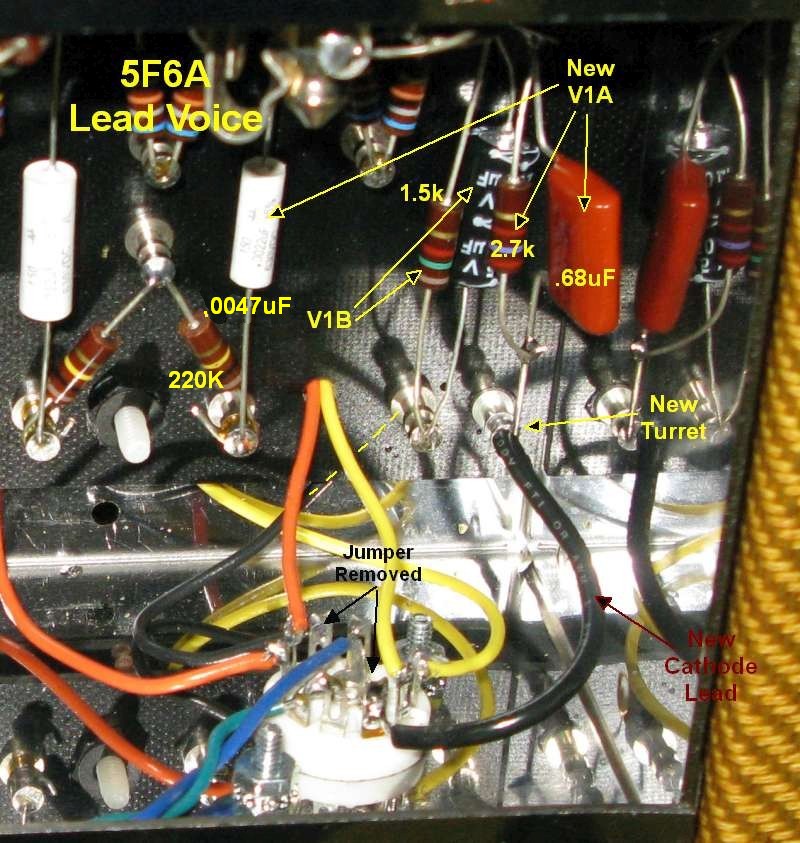
Lead Channel Mod
Modified components shown in pink. V1's cathodes are separated using two cathode resistors and two bypass caps. Don't forget to remove the cathode jumper between socket pins 3 and 8. The "Lead" channel gets a 220k 1 watt load resistor, 2.7k 1/2 watt cathode resistor, 0.68uF 25v bypass cap and a 0.0047uF 400v coupling cap. The unmodified channel needs a 1.5k 1/2 watt cathode resistor since only one cathode is drawing current through it. I also added a 500pF bright cap to the Normal volume pot to match the Marshall Plexi Lead channel.
Switchable Cascaded Channels for High Gain Channel
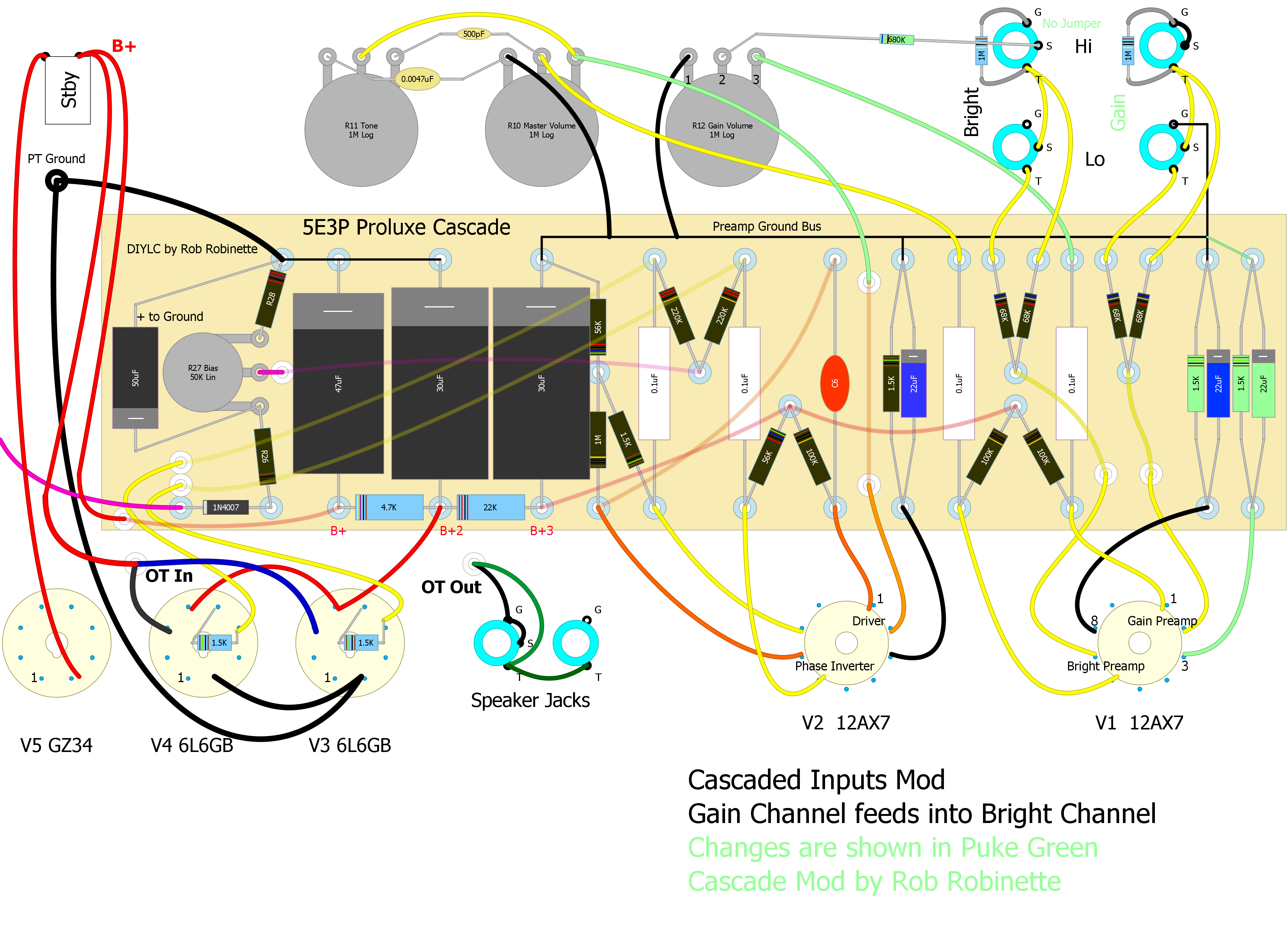
I wanted a Marshall style lead 'Gain Channel' for my Fender 5E3 tweed Deluxe clone so I came up with a channel cascade switch. When engaged it loops one channel into the other for an added gain stage. This simple mod is like having a built-in all tube overdrive pedal. It reroutes the Normal channel after it goes through the V1A preamp tube into the Bright channel to cascade their gain stages together. The result is the Normal channel becomes a 'Gain' channel who's gain is controlled by a dedicated 'Gain' preamp volume control so you can dial in as much tube overdrive as you want.
The cool thing is you can dial in preamp tube overdrive even at very low 'Master' volume levels. Also the Bright Channel is completely unchanged--it sounds exactly the same after this mod so you can still get all the sweet 5E3 Deluxe tone you need. There's even a switch option shown below so you can switch between a completely 'normal' 5E3 and this cascade mod. The Cascade Channel mod is simple to do and simple to reverse if you ever want to go back. This mod pairs really well with the "Lead" channel mod which cuts out the excess bass on one channel that can make the 5E3's fat bottom overdrive tone so messy. If you don't want to do the whole "Lead" channel mod just replacing the Normal channel's huge .1uF coupling cap with a Marshall sized .0047uF will go a long way in tightening up the overdrive bottom end. Reducing the size of the first preamp coupling cap will filter out the booming lows from the guitar but the larger downstream coupling caps will allow low frequency harmonics through which will fatten up the bottom end without being flabby or farty.
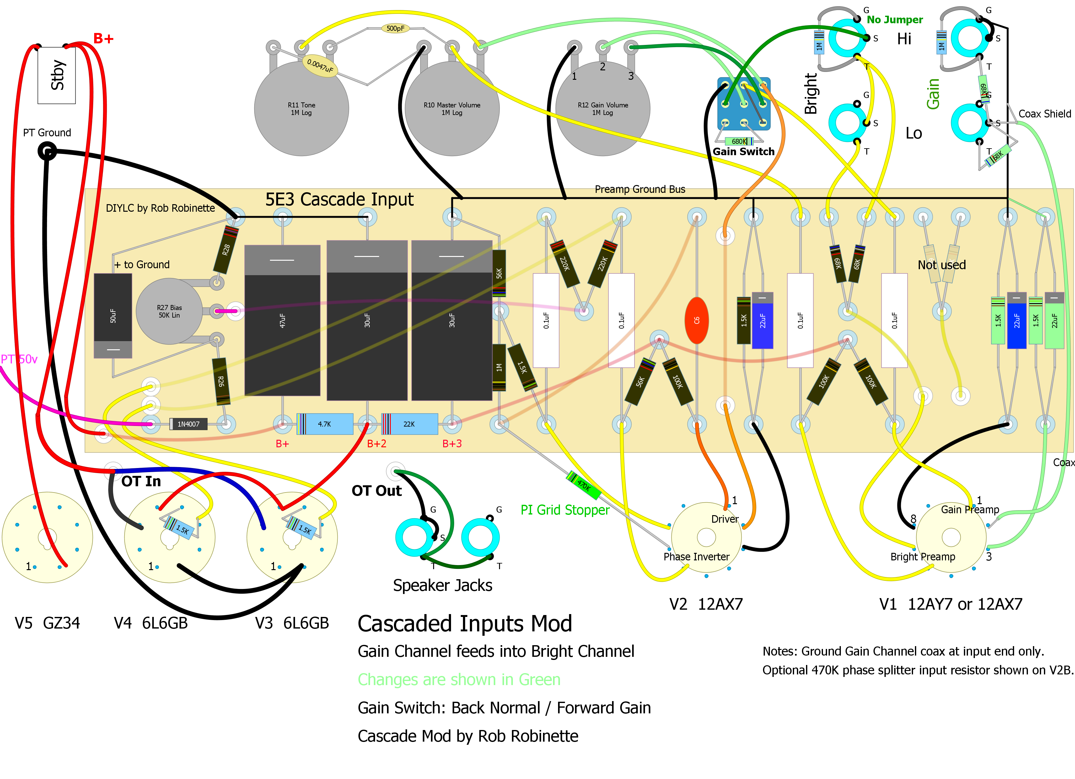
5E3 Deluxe With Cascaded Channels - Basic Mod
Changes in red. Normal Channel is rerouted to Bright Hi input jack switch terminal. Normal Volume pot becomes 'Gain' Volume. V1A and B's cathodes must be separated by installing a 1.5k ohm (1/2watt or higher) cathode resistor and one or two 22µF 25v cathode resistor bypass capacitors on V1A and V1B's cathodes (pins 3 & 8). The Gain Volume pot uses pin 3 for input and pin 2 (center wiper) for output. A 680k ohm resistor is added to pin 2 to limit Gain Channel gain.
Simple Cascade--No Switch and No Coax
Click on the image above for the full size layout. Changes are shown in 'Puke' Green. 'Gain' Channel gets amplified by V1A then feeds into the Bright Channel. The Normal Volume control becomes the Gain control and the Bright Volume control becomes the 'Master' Volume. Notice the V1 cathode bias resistors and caps at the far right of the circuit board. To separate V1A and B's cathodes you must change the existing cathode resistor from 870 ohms to 1.5k and install an additional 1.5k cathode resistor (a 22µF 25v bypass cap is optional for V1A as the extra gain it gives isn't needed). You must cut or remove the jumper on socket V1 between the cathodes (pins 3 and 8). You must also remove the jumper from the Bright Hi jack between the ground and switch terminals. You can download the editable DIYLC (DIY Layout Creator) layout file here: images\Guitar\5E3P Build\5e3p Tube Guitar Amplifier Cascade Inputs Coax.diy
When using the Bright Hi Channel simply turn down the Gain Volume and use the Master Volume and the amp will sound completely normal. The Gain Volume does interact with the Bright Lo volume so use both the Gain Volume and the Master Volume to control the Bright Lo volume.
Plug into the Gain Channel and use the Gain Volume to control the overdrive and use the Master Volume to control the overall volume. The new Gain Channel has a Hi and Lo input with the Lo input having the standard 6dB less signal.
This simple mod entails rerouting three wires at the volume controls, adding a resistor and separating the V1A and V1B cathode grounds. You must cut or remove the jumper on tube socket V1 between the cathodes (pins 3 and 8). You must also remove the jumper from the Bright Hi input jack between the ground and switch terminals.
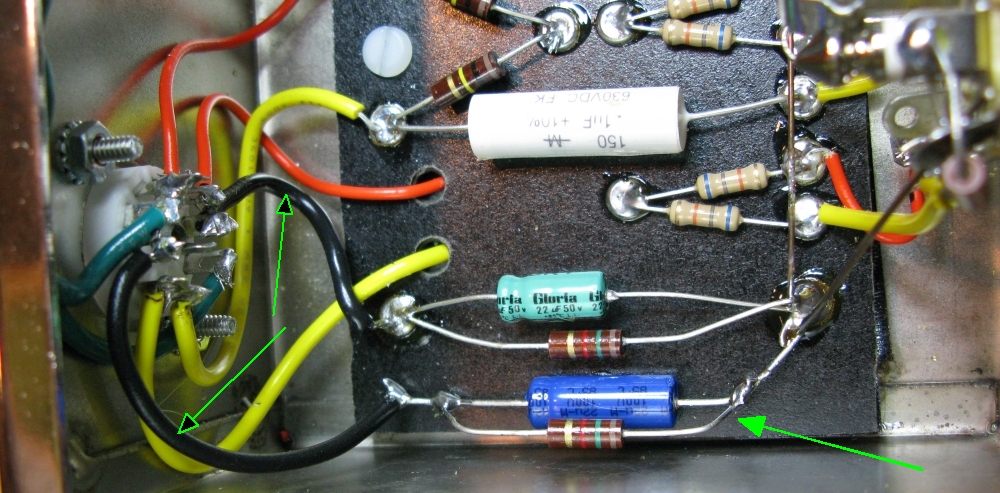
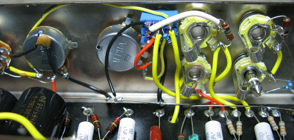
Separated Cathode Resistors & Caps
Cascade Mod + Gain Channel Coax
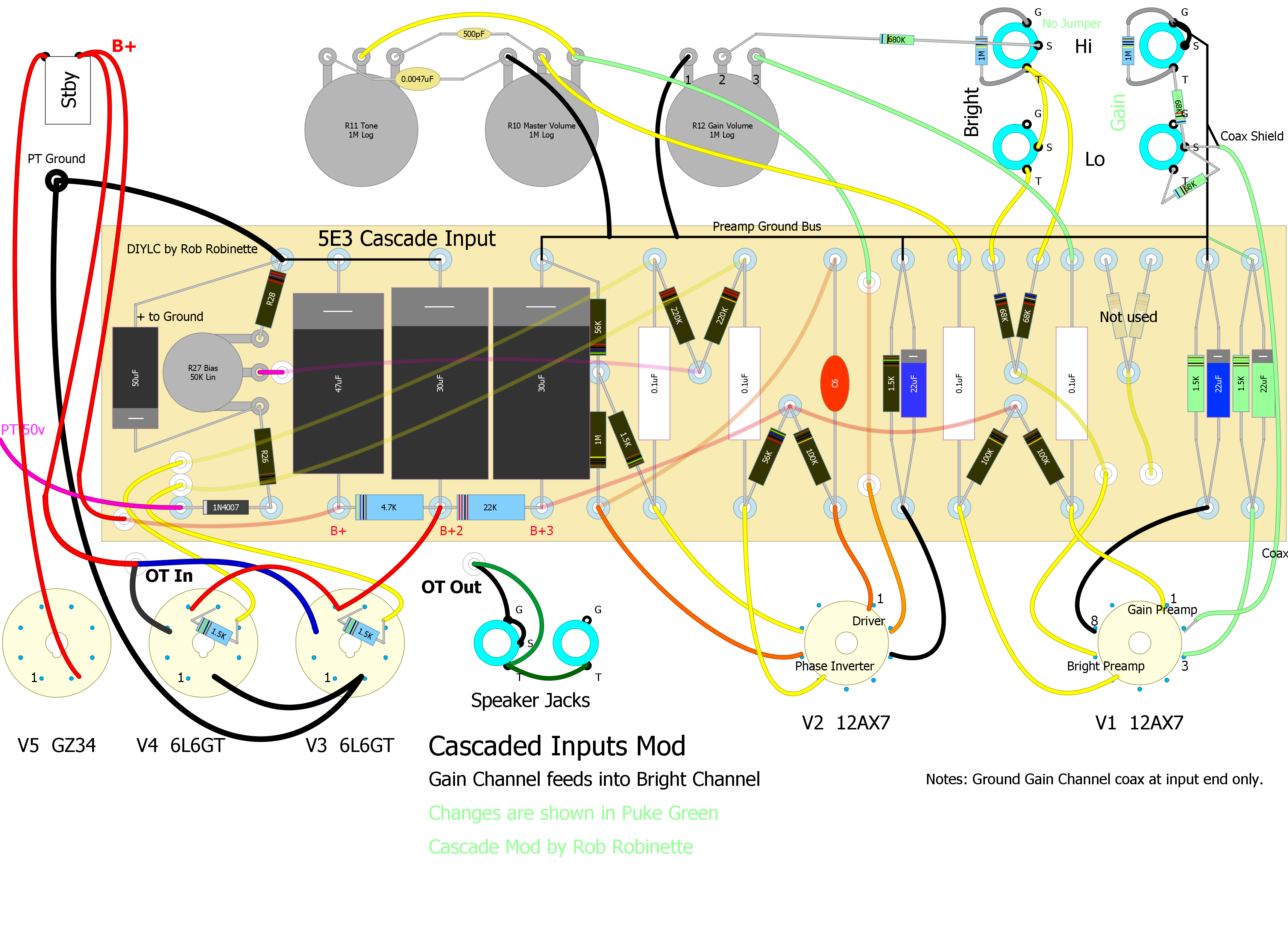
I recommend the use of coax for the Gain Channel. Using RG-174 coax from the Gain Channel input jacks to V1A can reduce noise. Putting the 68k grid stopper resistors on the input jack will reduce the input path's exposure to noise. Do not ground the coax shield at the tube end, only ground it to the Preamp Ground Bus or a Gain Channel input jack ground tab.
68k Grid Stopper Resistors Directly to Coax
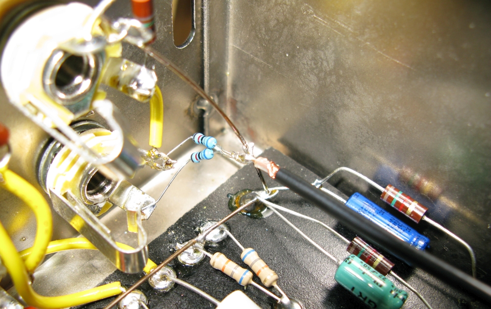
The coax shield is connected to the preamp ground bus bar to the right of the resistors.
Coax Connected to V1A Pin 2
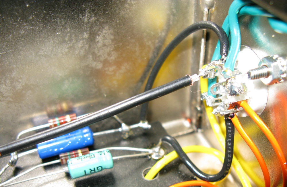
Coax shield is not grounded at this end. In this picture it looks like pin 3 is shorting to pin 2 but it isn't.
An Optional Switch for Standard 5E3 Parallel or Cascaded Channels
This is what I did and I really like being able to switch back and forth between standard 5E3 and cascaded channels. With switch lever IN you get standard 5E3 parallel input channels. With switch OUT the Normal Channel cascades into the Bright Channel for preamp tube overdrive.
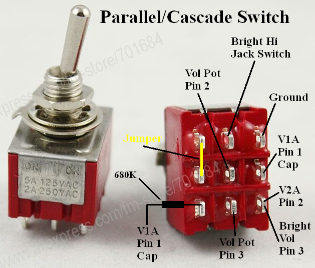
This ON-ON 3PDT switch will allow you to move between standard parallel 5E3 channels and cascaded overdrive. With the switch in 'Parallel' the only difference between a stock 5E3 is the separated cathode resistors on V1 which will have no impact on tone.
Parallel/Cascade Switch Installed
It's not pretty but it works great--this is a very cool mod.
One other modification I recommend with the cascaded overdrive channel is to add a Pre Phase Inverter Master Volume or simply add a 470KΩ 1/2 watt grid stopper resistor to the V2B Phase Inverter input (V2 pin 7) to smooth out the Phase Inverter overdrive tone. The cascaded overdrive signal can really overwhelm the Phase Inverter and cause severe and nasty sounding clipping. A Pre Phase Inverter Master Volume will allow you to control how much Phase Inverter distortion is fed into the Power Tubes. These modifications can really sweeten the 5E3's overdrive tone. By adding a resistor or master volume the 5E3's sweet preamp tube distortion won't get chopped up in the phase inverter.
I'm very happy with the cascaded channel mod. I can dial in tube overdrive distortion on the Gain channel even at low Master volume levels and the Bright Hi channel is completely 5E3 Deluxe. You can also dial the Gain volume down and get a normal sounding Normal Hi and Lo tone.
1/4 Power Switch
Note: Most people will be happier with the 10% Power Switch in the next section.
The original 1/4 Power Switch is from the 20 watt Fender Eric Clapton Tremolux. The switch cuts the amp's output power by 75%. The switch places an 8 ohm 25 watt resistor in series with the 8 ohm amplifier speaker (for a total of 16 ohms and a 50% cut in power), then places a 16 ohm 25 watt resistor in parallel to bring the total speaker load back down to 8 ohms and gives another 50% cut in power. The two resistors turn 3/4 of the amp's output signal into heat. With the switch in the "Normal" position the 8 ohm resistor is bypassed and the 16 ohm resistor is disconnected.
The Eric Clapton Tremolux is a 2x6V6 fixed bias amp putting out about 20 watts so this circuit will work with any amp with similar or lower output.
You can use the 1/4 Power Switch with the internal speaker and an external cab simultaneously (I don't know why you'd want to) but the speakers' load will drop to 4 ohms so most of the power will bypass the 16 ohm resistor and flow through the 8 ohm resistor and speakers. Total load on the output transformer drops to 6.8 ohms but the Fender 8 ohm transformer is designed to work with two parallel speakers at a 4 ohm load so it's not a problem.
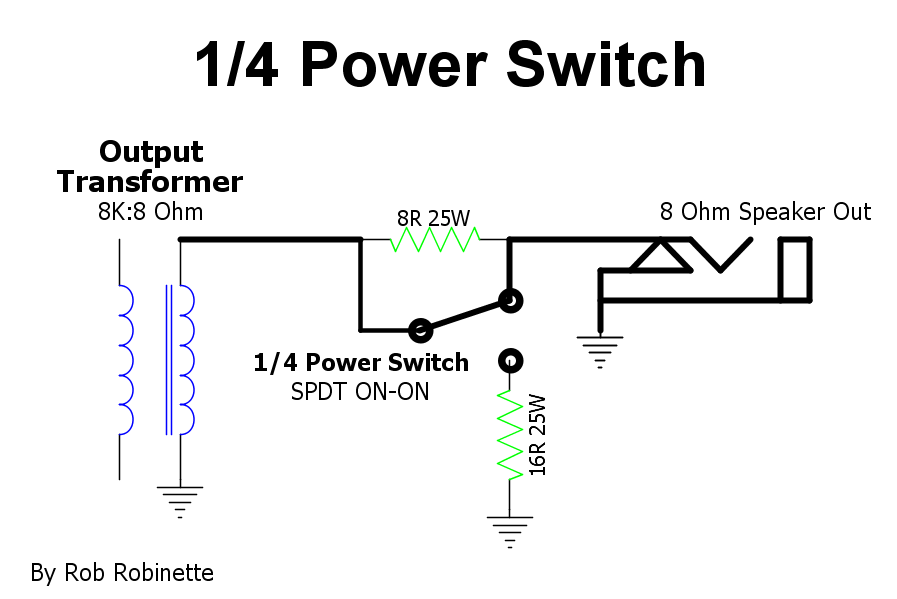
The 8 ohm 25w resistor is placed in series with the amplifier speaker and the 16 ohm 25 watt resistor is placed in parallel to bring the total speaker load back down to 8 ohms. If your amp does not have an Aux speaker jack just connect the 16 ohm resistor and switch wire to the speaker jack's Tip and Ground terminals.
This Layout Fits The 5E3
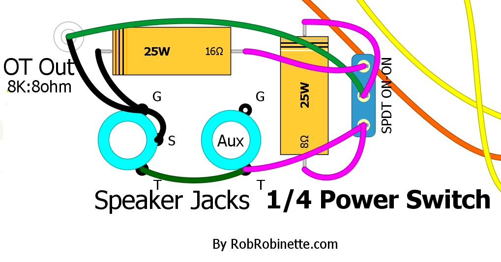
T=Tip and G=Ground.
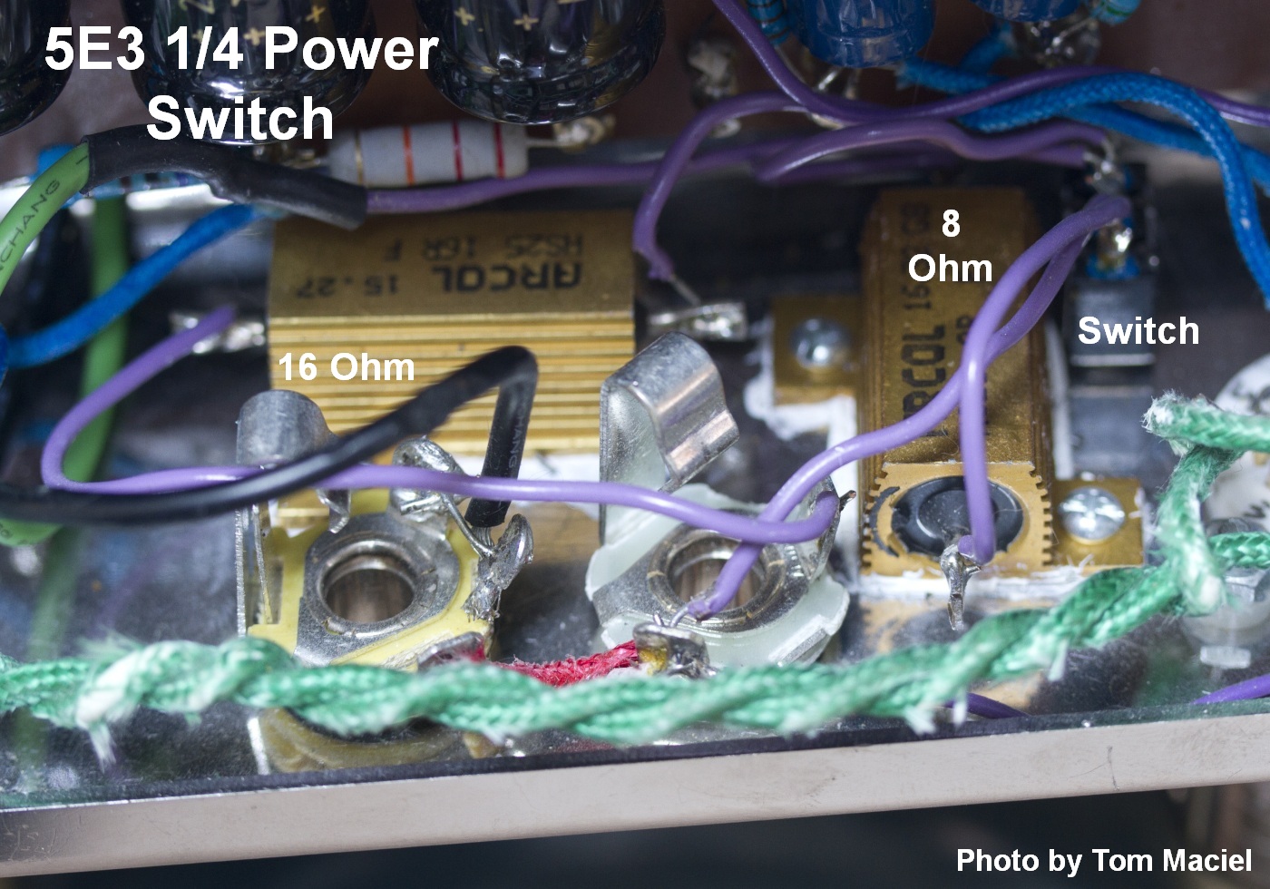
Large, gold colored 25 watt chassis mount resistors with 1/4 Power Switch at upper right. Photo by Tom Maciel.
Mouser.com: 8 ohm 25 watt wire wound chassis mount resistor, 16 ohm 25 watt resistor. The resistors are about $3 each.
These are chassis mount resistors and should be screwed or bolted to the chassis to dissipate heat. If they are not bolted to the chassis their heat rating drops to about 5 watts.
For a 4 ohm output transformer secondary change the resistors to a 4 ohm 25 watt and 8 ohm 25 watt.
For a 16 ohm output transformer secondary change the resistors to a 16 ohm 25 watt and 32 ohm 25 watt.
For a 1x6V6 cathode biased amp like the 5F1 Champ, 10 watt chassis mounted resistors would be fine.
10% Power Switch
Several builders have complained that the 1/4 Power Switch shown above, which cuts 75% of the output power, only sounds like a 30 to 50% volume cut due to how our ears perceive volume. If you really want near-bedroom volume levels then a 90% cut in power can be attained by using a 16 ohm 25W resistor for the upper resistor and a 12 ohm 25W resistor for the lower resistor (8 ohm output transformer secondary). The 12 ohm resistor will burn most of the amp's output so for anything more powerful than a cathode biased push-pull 6V6 amp like the 5E3 Deluxe you'll need to bump the 12 ohm resistor's power handling to 50 watts to be safe (two 25 ohm 25 watt resistors in parallel will work).

90% of the amp's output power will be converted to heat.
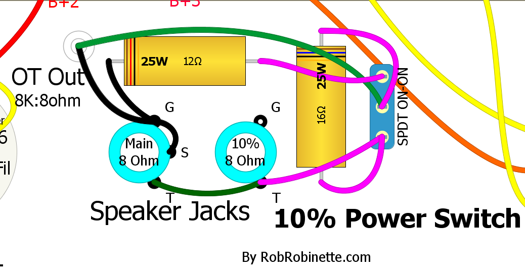
With the switch set to 10% both jacks will be 8 ohm with 90% of the amp power turned into resistor heat. These 25 watt resistors are adequate for 15 watt amps such as a 5E3 Deluxe or other cathode biased 6V6 push-pull amps.
These are chassis mount resistors and should be screwed or bolted to the chassis to dissipate heat. If they are not bolted to the chassis their heat rating drops to about 5 watts.
For 25 watt amps such as a blackface or silver face Deluxe or other fixed bias 2x6V6 push-pull amps I recommend 50 watt resistors (two 25 watt resistors in parallel will also give you 50 watts).
For 50 watt amps such as 2x6L6 amps I recommend 100 watt resistors (two 50 watt resistors in parallel will also give you 100 watts).
For a 100 watt amp such as 4x6L6 amps I recommend 200 watt resistors (two 100 watt resistors in parallel will also give you 200 watts). These would be difficult to stuff into an amp chassis.
For a 2 ohm output transformer secondary you would use 3 and 4 ohm resistors.
For a 4 ohm output transformer secondary you would use 6 and 8 ohm resistors.
For a 16 ohm output transformer secondary you would use 24 and 32 ohm resistors.
If your amp has a negative feedback loop then tap it from the main speaker jack tip connection.
10% Power Jack
You can wire your speaker aux jack as a 10% power output jack. This mod uses the circuit above but uses the main speaker jack switch to switch between full power and 10%.

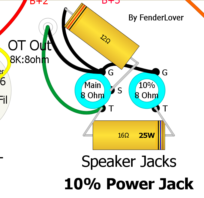
The main speaker jack on the left is 8 ohm full power. The 10% jack on the right is 8 ohm but 90% of the amp output power is burned in the two 25 watt resistors. These 25 watt resistors are adequate for 15 watt amps such as a 5E3 Deluxe or other cathode biased 6V6 push-pull amps.
These are chassis mount resistors and should be screwed or bolted to the chassis to dissipate heat. If they are not bolted to the chassis their heat rating drops to about 5 watts.
For 25 watt amps such as a blackface or silver face Deluxe or other fixed bias 2x6V6 push-pull amps I recommend 50 watt resistors (two 25 watt resistors in parallel will give you 50 watts).
For 50 watt amps such as 2x6L6 amps I recommend 100 watt resistors (two 50 watt resistors in parallel will also give you 100 watts).
For a 100 watt amp such as 4x6L6 amps I recommend 200 watt resistors (two 100 watt resistors in parallel will also give you 200 watts). These would be difficult to stuff into an amp chassis.
For a 2 ohm output transformer secondary you would use 3 and 4 ohm resistors.
For a 4 ohm output transformer secondary you would use 6 and 8 ohm resistors.
For a 16 ohm output transformer secondary you would use 24 and 32 ohm resistors.
If your amp has a negative feedback loop then tap it from the main speaker jack tip connection.
10% Power In External Box
This is the 10% power circuit in a box. The amp speaker out plugs into the IN jack and the speaker is plugged into the OUT jack.
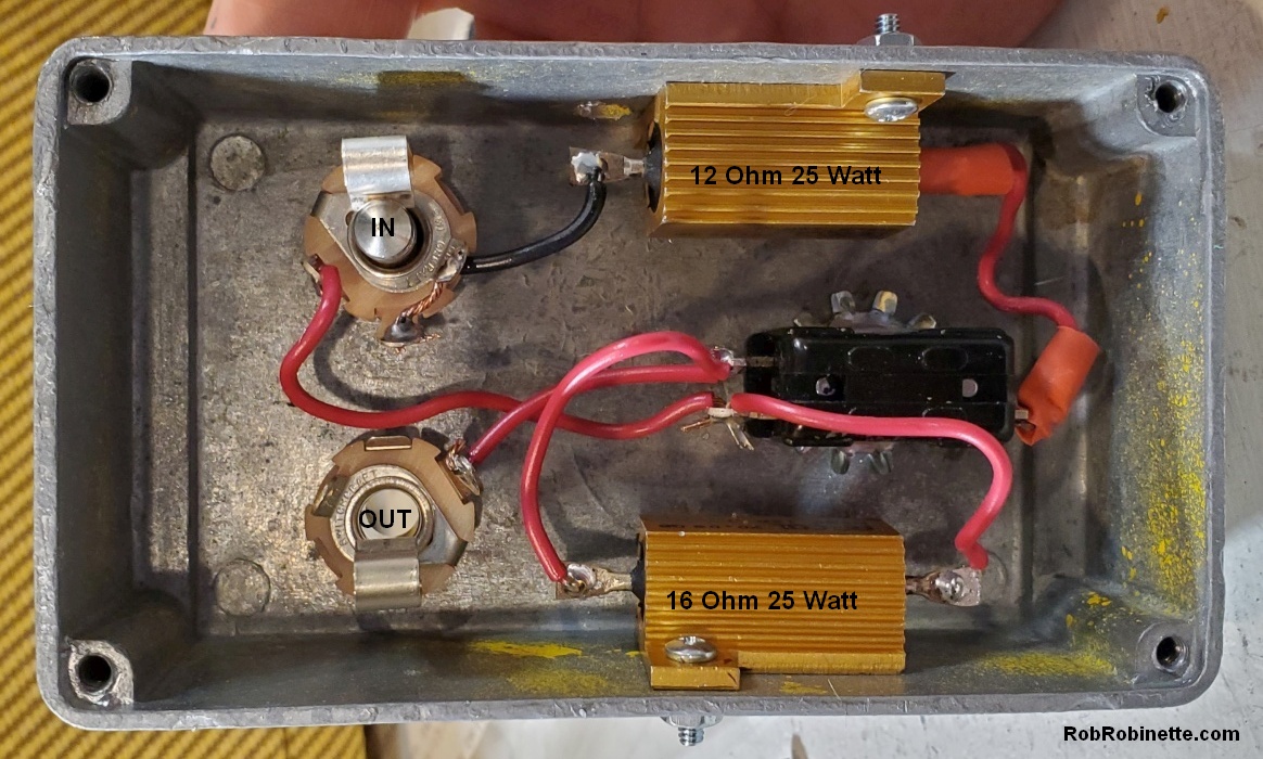
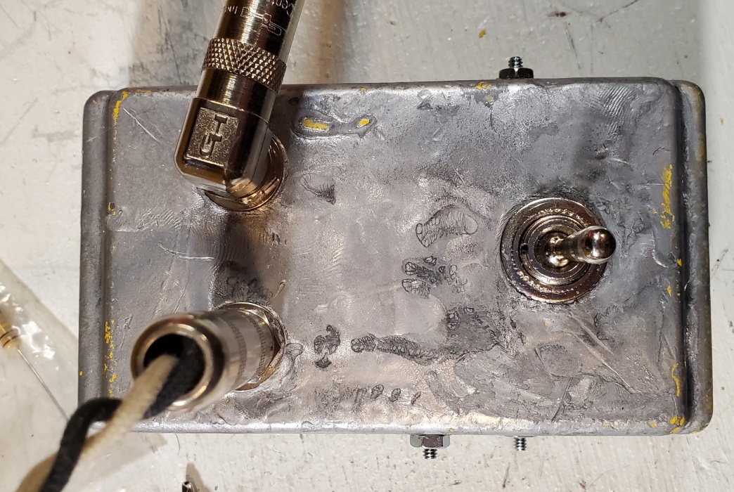
These are chassis mount resistors and should be screwed or bolted to the box to dissipate heat. If they are not bolted to the chassis their heat rating drops to about 5 watts.
For 25 watt amps such as a blackface or silver face Deluxe or other fixed bias 2x6V6 push-pull amps I recommend 50 watt resistors (two 25 watt resistors in parallel will also give you 50 watts).
For 50 watt amps such as 2x6L6 amps I recommend 100 watt resistors (two 50 watt resistors in parallel will also give you 100 watts).
For a 100 watt amp such as 4x6L6 amps I recommend 200 watt resistors (two 100 watt resistors in parallel will also give you 200 watts). I don't recommend this because the box would have to be really big to provide an adequate heat sink for the big resistors.
For a 2 ohm output transformer secondary you would use 3 and 4 ohm resistors.
For a 4 ohm output transformer secondary you would use 6 and 8 ohm resistors.
For a 16 ohm output transformer secondary you would use 24 and 32 ohm resistors.
1/2 Power Switch
This is a standard 'Pentode / Triode' type switch that lowers the power tube output for lower maximum volume. In reality this switch changes the 6V6 power tube from a pentode (5 electrodes: cathode, control grid, plate, screen grid and suppressor grid) to a tetrode (4 electrodes since the screen grid is deactivated) but by convention we call it a pentode / triode switch.
A triode tube's plate normally 'pulls' free electrons from the cathode but a triode's plate voltage fluctuates as it amplifies a guitar audio signal. When the plate voltage drops it does not pull electrons as hard as it does when the plate voltage is high. Adding a fixed, high voltage screen grid makes a tube much more efficient because the screen's constant strong pull of electrons does not drop when the plate's voltage drops so the tube flows more electrons.
The Half Power Switch (ON-ON DPDT mini switch) connects the power tube screens (pin 4) to B+2 (normal full power pentode) or to the power tube plates (pin 3 for half power 'triode' mode). Removing B+2 and tying the power tubes' screen and plate together deactivates the screen by allowing the screen voltage to fluctuate along with the plate voltage effectively creating a lower power 'triode.' Running a pentode in 'triode' mode definitely changes its clean and overdrive tone so it's more than just a 'half power' mode.
Half Power Switch in the BootHillAmps.com SixShooter
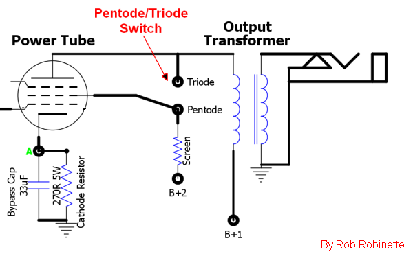
Power tube screen grid is connected to either the plate in the triode mode, or the B+2 screen power supply in the pentode mode.
This is a simple mod because there's room between the power tubes for the mini switch so the resistors can be connected directly between the tube sockets and switch. 470Ω 2 watt screen resistors are added to keep the screen voltage slightly lower than plate voltage. These resistors have no effect on amp tone but give the added benefit of protecting the power tubes from excessive screen current which can extend the life of your power tubes.
With the switch lever 'IN' you get normal full power. With the lever 'OUT' you get 'tetrode' half power.
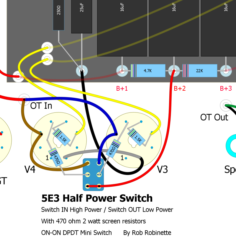
This is my recommended layout with 470Ω screen resistors always in circuit to provide excess screen current protection.
Alternate Design With Screen Resistors Used only For Low Power
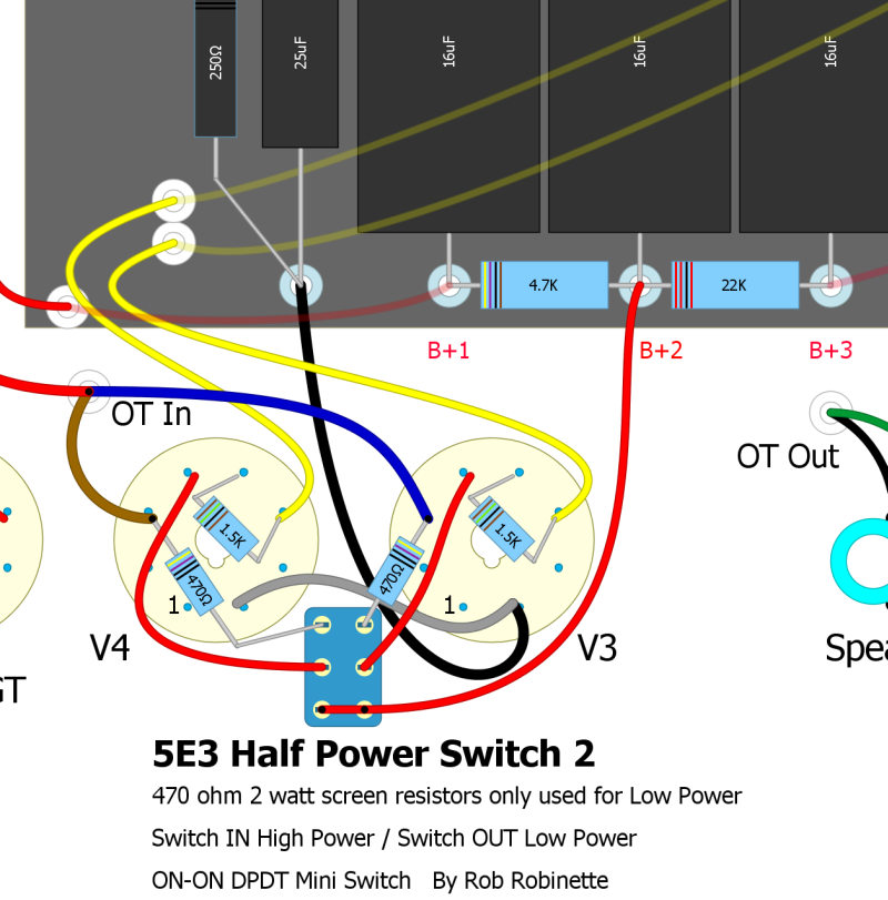
470Ω Screen Resistors moved to switch input so they are only used in the 'Low Power' switch position. Use this layout if you don't want to alter your 5E3's circuit with the switch in the normal 'High Power' position.
100 Watt Half Power Switch
For quad power tube amps you can safely switch off two of the power tubes by breaking a pair of power tubes' cathode connection to ground. This will stop all current flow through the tubes and cut output by 50%. You won't get a 50% output volume cut but it will help tame these beasts.
You need to disconnect one tube from each side of the push-pull pairing. For example in the Fender Twin Reverb you would disconnect tubes V7 & V10 (see layout below).
A simple SPST (single post single throw) ON-OFF mini-toggle switch will do the job. Insert the switch between the power tubes' cathode (pin 8) ground wire. Switch closed is normal quad tube power, switch open will turn off two tubes.
For best tone and amp loading you should make a speaker impedance adjustment up one notch. Since current into the output transformer is cut in half we need twice the load on the transformer secondary to compensate. For example connect a 16 ohm speaker to an 8 ohm speaker jack but most amps will run fine with this amount of impedance mismatch.
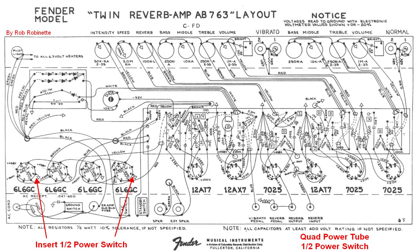
Insert ON-OFF switch between power tube socket pin 8 (cathode) and ground. Note how V7 and V8 share the blue output transformer wire--they are in parallel so we can turn off V7 with the cathode switch. The same goes for V9 and V10--they share the brown output transformer wire.
Paul C Mod
The Paul C Mod changes the typical cathodyne phase inverter from cathode bias to fixed bias to offer more clean headroom and give a more balanced output.
The mod creates a fixed bias on the phase inverter grid by creating a voltage divider with the 2.2M Bias resistor and 1M Grid Leak. If the phase inverter power node is around 250v the grid voltage after the divider will be +75v. The cathode will be at an even higher voltage of around +77v due to the 56k PI Tail Load resistor so the difference between grid and cathode results in a fixed negative bias voltage of around -2v. This leads to a more balanced bias point and reduces harsh "double frequency" overdrive created by excessive plate clipping.
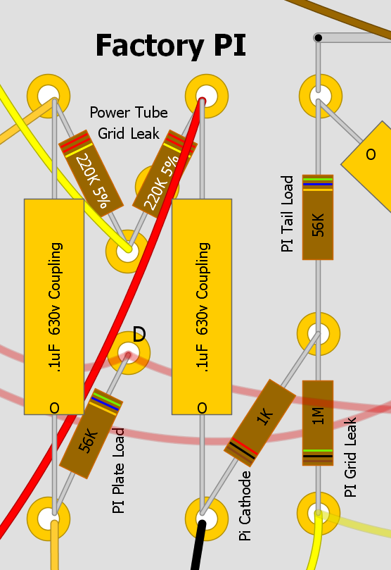
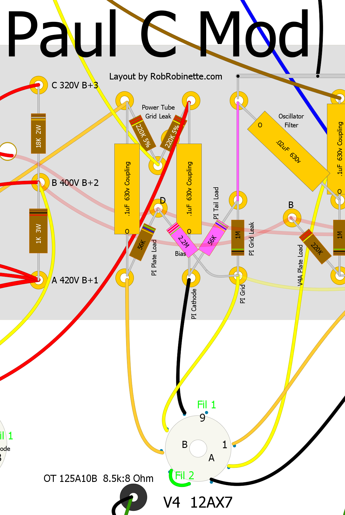
Typical phase inverter and the Paul C Mod. Remove the 56k PI tail load resistor and replace it with a jumper. Remove the 1k PI cathode resistor and replace it with the 56k resistor removed in the previous step. A 2.2M bias resistor is added and connects the grid to the same power node as the 56k PI plate load resistor.
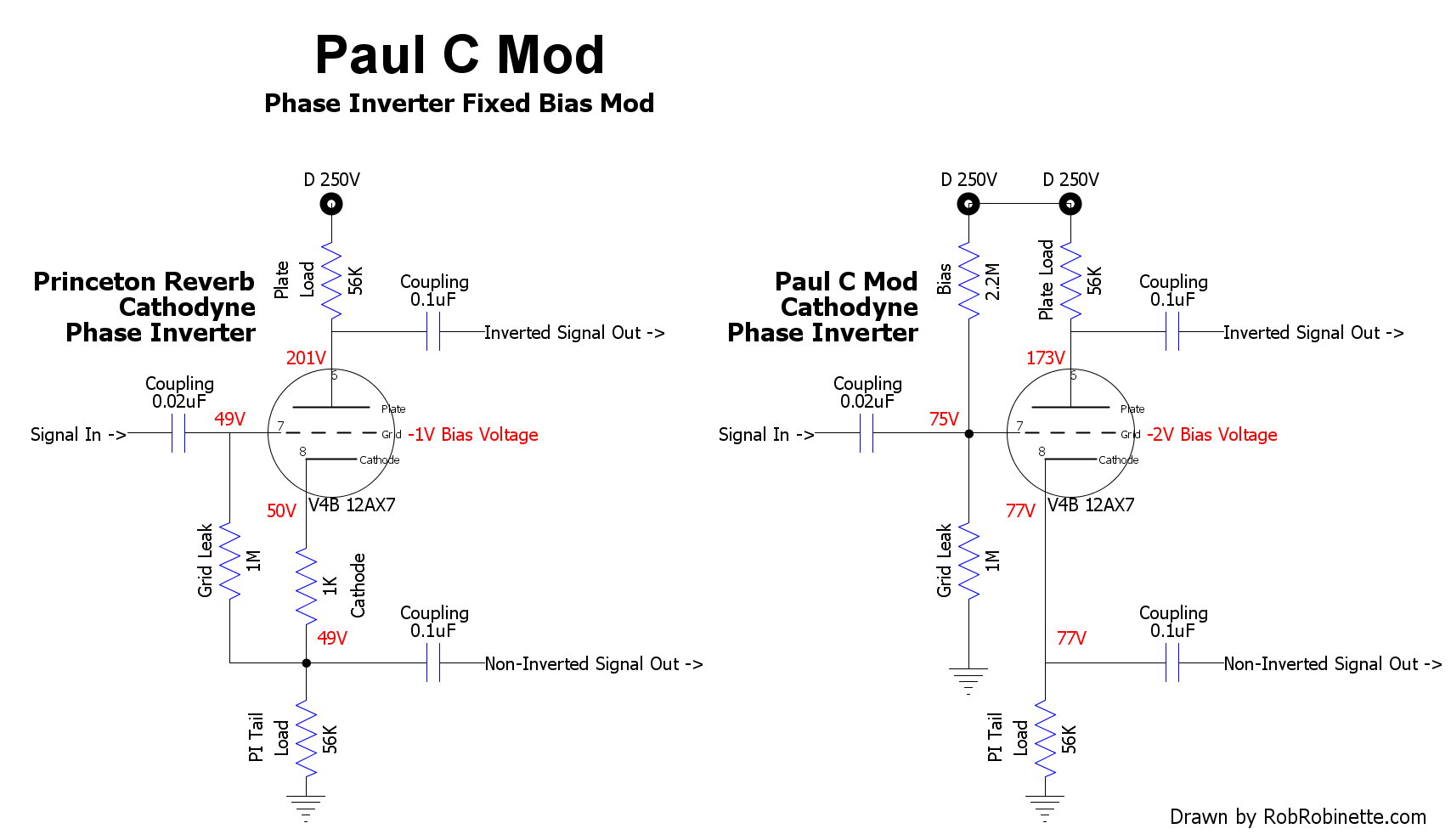
The Paul C Mod can be applied to any cathodyne phase inverter not just the Princeton Reverb. The Paul C Mod's 2.2M bias resistor forms a voltage divider with the 1M grid leak to set the fixed bias voltage. The grid leak resistor is grounded and the cathode resistor is not needed so it is deleted.
FX Loop
Add a simple, passive FX loop. High gain effects like boost, reverb and delay sometimes sound best when inserted after the first gain stage and volume/tone circuit. This simple mod works really well so I add them to most of my amp builds. The Normal volume control works as the "send level" control.
The Send jack can also be used as a preamp out to another amp or recording rig. The Return jack can be used as a "power amp in" jack. You can also plug your guitar into the Return jack to bypass one gain stage and the volume/tone circuit for a really clean, low gain, unprocessed tone. When plugging a guitar into the Return jack you will have to control the volume with your guitar's volume control.
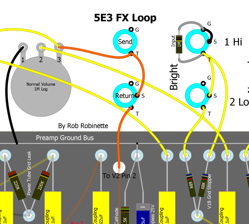
Insert the jacks between the Volume pot's out and the following gain stage. The upper "Send" jack is non-switched Switchcraft 11 jack, the lower "Return" jack is a three terminal Switchcraft 12A jack with shunt (switch)--just like the input jacks.
Here's a buffered, zero-loss, $85 FX loop kit that gets great reviews: Metroamp Zero-Loss FX Loop Kit
FX Loop With True Bypass Switch
This DPDT mini switch allows true bypass of a passive FX loop.

If your jacks are grounded to the chassis you can eliminate the three black ground wires.
Change the Tone Cap Value
The 5E3's tone cap is an enormous 4,700pF which partly causes the strange tone and volume interaction we love about the 5E3. The problem is it's such a large capacitor it dips into the mid frequencies and cuts the highs and mids when turning down the tone control.
Dropping the tone cap size down to around 820pF will leave the mid frequencies alone but allow you to cut the harshness some brighter guitar pickups exhibit.
Framus Mid Tone Control
This simple mid tone control was used in the Framus Cobra amp. It allows you to turn down the mids and go from a flat tweed frequency response to a mid scooped blackface tone. Use your guitar tone control to control the highs and you've got a pretty flexible tone setup.
On amps with a single tone control you can leave it in place and connect the output of the Volume pot to the input of this Mid Control and have both a high bleed Tone Control and this Mid Control. You can also remove the original Tone Pot if you like and just wire it as a Mid Control.

Simple but effective mid tone control.
The component values can vary from 100k to 1M for the tone pot, .01uf to 1000pF (50 volts or higher, polypropylene or polystyrene) for the tone caps and 10k to 100k (1/4 watt or higher) for the resistor. A 100k resistor reduces the depth of the mid scoop and places a lighter load on the signal compared to a 10k resistor.
Connect the 100k resistor to your preamp ground bus. The Mid Control must be downstream of a coupling cap to keep high voltage DC out of the Mid pot.
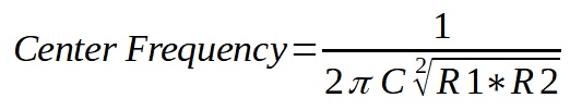
If you break the connection between the caps and resistor or resistor and ground with a switch you can eliminate the tone circuit's effect by opening the switch. This is called a Raw Switch because it lets raw, unfiltered guitar signal through.
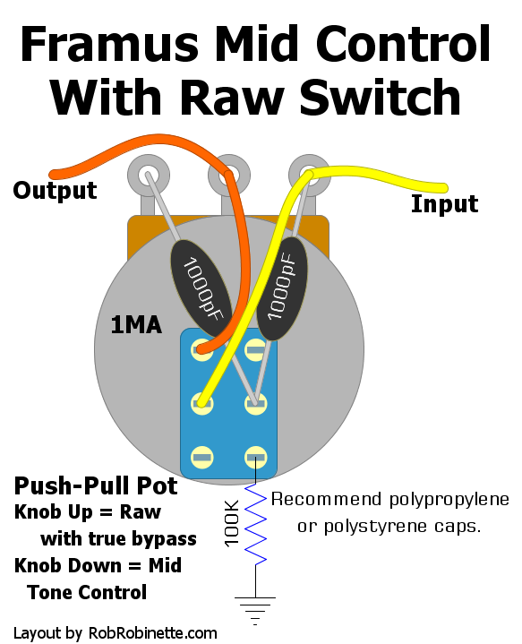
Push-Pull 1MA (audio) pot wired as a "Raw Switch" with true bypass. Pulling the knob up breaks the connection between the caps and resistor so the guitar audio is not filtered. Special thanks to "FenderLover" for the idea of the "true bypass" (two wires on the left side of the switch).
Point-to-Point Passive Baxandall or James TB Tone Stack
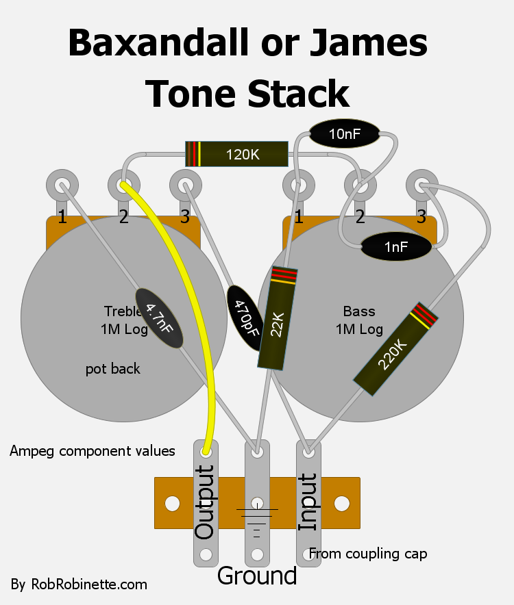
The James (or passive Baxandall) Treble/Bass tone stack allows more control with less quirks than the Fender/Marshall/Vox TMB tone. Unlike the Fender tone stack you can achieve a mid hump by setting the treble and bass controls low.
Note: The Baxandall or James tone stack must have a coupling cap between itself and a tube plate. It cannot function as a coupling cap like the Fender/Marshall/Vox TMB tone stack.
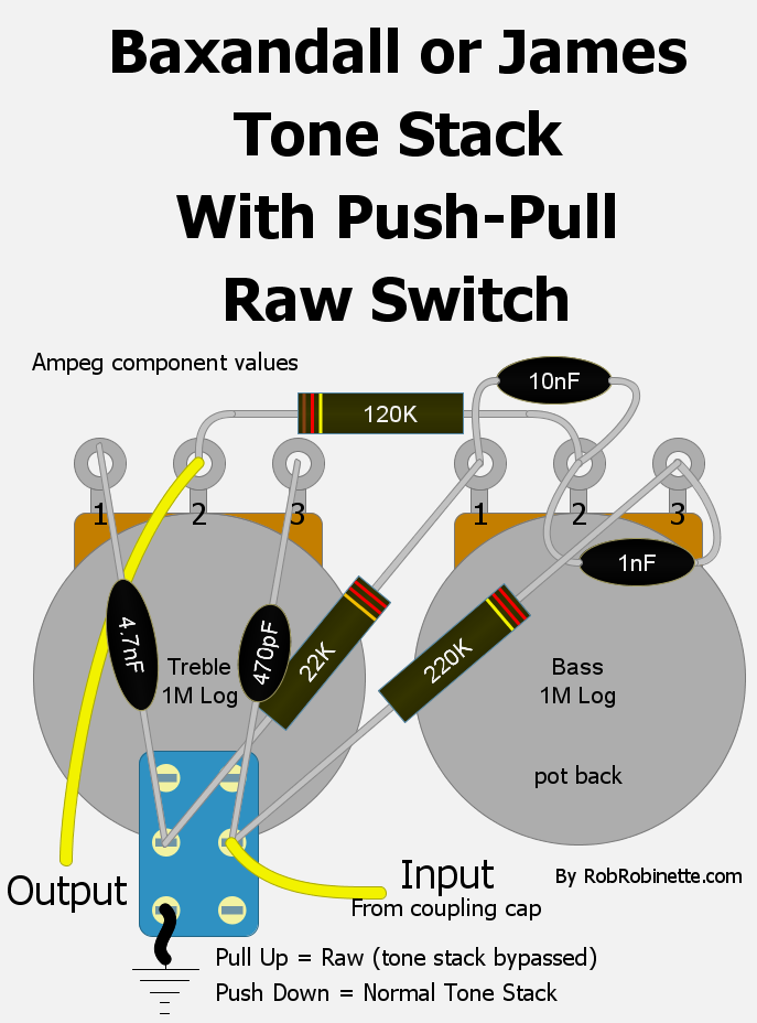
A 1MA Push-Pull Pot can be used as a Raw switch to effectively remove the tone circuit from the amp. When you remove the circuit's ground by pulling the Treble knob up all the tone shaping and circuit load disappear. More info on the tone circuit here.
Bass Tone Control
This is a simple Bass Tone Control. As you turn the pot down it removes bass frequencies. It uses a very small mica cap in line with the audio signal which strips out low frequencies. A 1MRA (1 megaohm reverse audio or anti-log) pot wired as a variable resistor gives you a variable cap bypass. As you turn the Bass pot up (clockwise) less signal goes through the cap and less bass is cut. At full up (clockwise pot rotation) the cap is fully bypassed so all frequencies pass around the cap and normal, full frequency amp tone is passed. Run the control at full up (full clockwise) for normal, full frequency tone because at full bypass the Bass Tone Control circuit disappears.
The corner frequency of the Bass Tone Control changes with signal impedance but the 500pF cap will work at most places in the amp circuit. A high impedance signal will pass lower frequencies through the cut cap so if you need more control authority then reduce the cap size to 250 or even 100pF.
The Bass Tone Control circuit cannot be used as a coupling cap (blocking cap) because the pot will allow DC to pass. The Bass Tone Control must be placed downstream of a coupling cap to keep DC out of the pot.
The Bass Tone Control circuit is a small value cap with a variable bypass. More bypass gives you more bass, fully bypassed (full clockwise rotation) gives you a normal, full frequency signal. The mica cap should be rated for 100v or higher. Download the pdf here and the DIYLC file here.
Bass Cut Control
This control is the opposite of the above Bass Tone Control. As you turn the pot up it reduces bass. It uses the same very small mica cap in line with the signal which strips out low frequencies. A 1MA pot wired as a variable resistor gives you a variable cap bypass. As you turn the Bass Cut pot up (clockwise) more signal goes through the cap and more bass is cut. At full down (counter-clockwise pot rotation) the cap is fully bypassed so all frequencies pass around the cap and normal, full frequency amp tone is passed. Run the control at full down (full counter-clockwise) for normal, full frequency tone because at full bypass the Bass Cut circuit disappears.
The corner frequency of the Bass Cut Control changes with signal impedance but the 500pF cap will work at most places in the amp circuit. A high impedance signal will pass lower frequencies through the cut cap so if you need more control authority then reduce the cap size to 250 or even 100pF.
The Bass Cut Control circuit cannot be used as a coupling cap (blocking cap) because the pot will allow DC to pass. The Bass Cut Control must be placed downstream of a coupling cap to keep DC out of the pot.
The Bass Cut Control circuit is a small value cap with a variable bypass. More bypass gives you more bass, fully bypassed (full counter-clockwise rotation) gives you a normal, full frequency signal. The mica cap should be rated for 100v or higher. Download the pdf here and the DIYLC file here.
Volume/Sizzle Control
The Sizzle Control is a wide range tone control that pairs with a volume pot and bright cap. The Bright Cap does double-duty as a standard volume pot bright cap which brightens tone as the Volume pot is rolled down but it also works with the Sizzle Control. When the Sizzle Control is turned up the bright cap passes high freqs around the Sizzle pot.
As the Sizzle Control is turned down, the Bright Cap becomes less effective and as you continue to turn down the Sizzle Control high frequencies are actually bled to ground through the Dull Cap. The Max Dull Resistor sets the maximum amount of high frequencies that can be filtered out. With boosted highs up high and filtered highs down low the Volume/Sizzle Control has a wide range of tonal authority.
The Max Dull resistor is 1/2 watt or greater and sets the maximum dullness when the Sizzle pot is turned full down. It can range from 68k to 100k. Both caps should be polypropylene or polystyrene and any voltage rating at or above 100v.
Note: The Volume/Sizzle Control must have a coupling cap between itself and a tube plate. It cannot function as a coupling cap like the Fender/Marshall/Vox TMB tone stack.
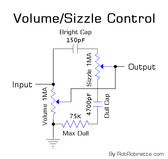
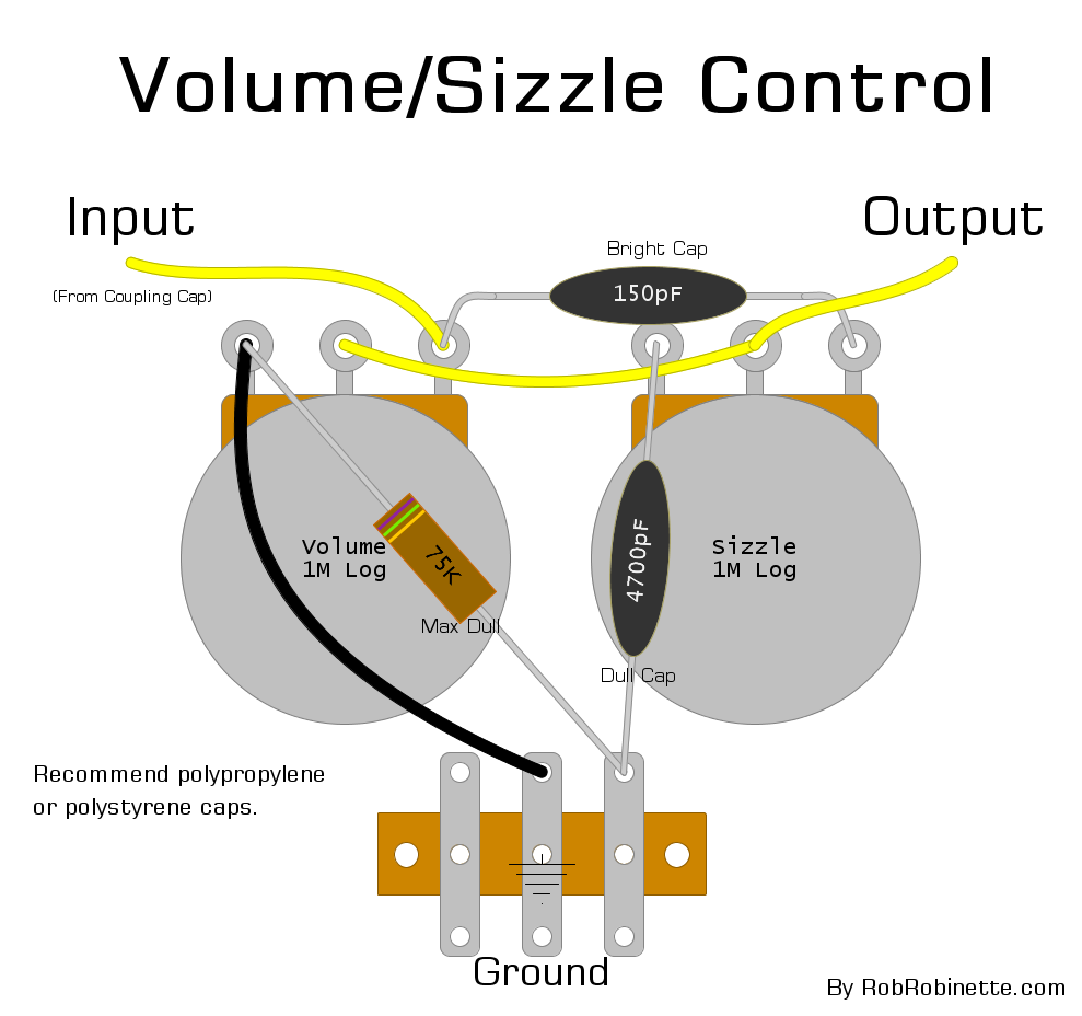
The Volume/Sizzle Control also works well between stages as a "Gain/Sizzle Control". If you need to cut some inter-stage signal level in your high gain preamp, use the Gain/Sizzle Control with Attenuator shown below. A 470k Attenuator Resistor cuts 32% of the input signal at max volume. The value of the Attenuator Resistor can be adjusted to trim the signal level to meet the needs of the following gain stage. A 1M Attenuator Resistor would cut 50% of the input signal. Make the Attenuator Resistor smaller and the signal cut decreases.
Note: The Gain/Sizzle Control must have a coupling cap between itself and a tube plate. It cannot function as a coupling cap like the Fender/Marshall/Vox TMB tone stack.
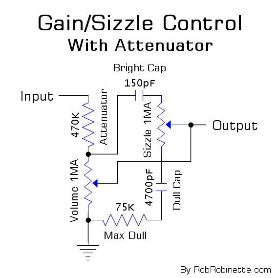
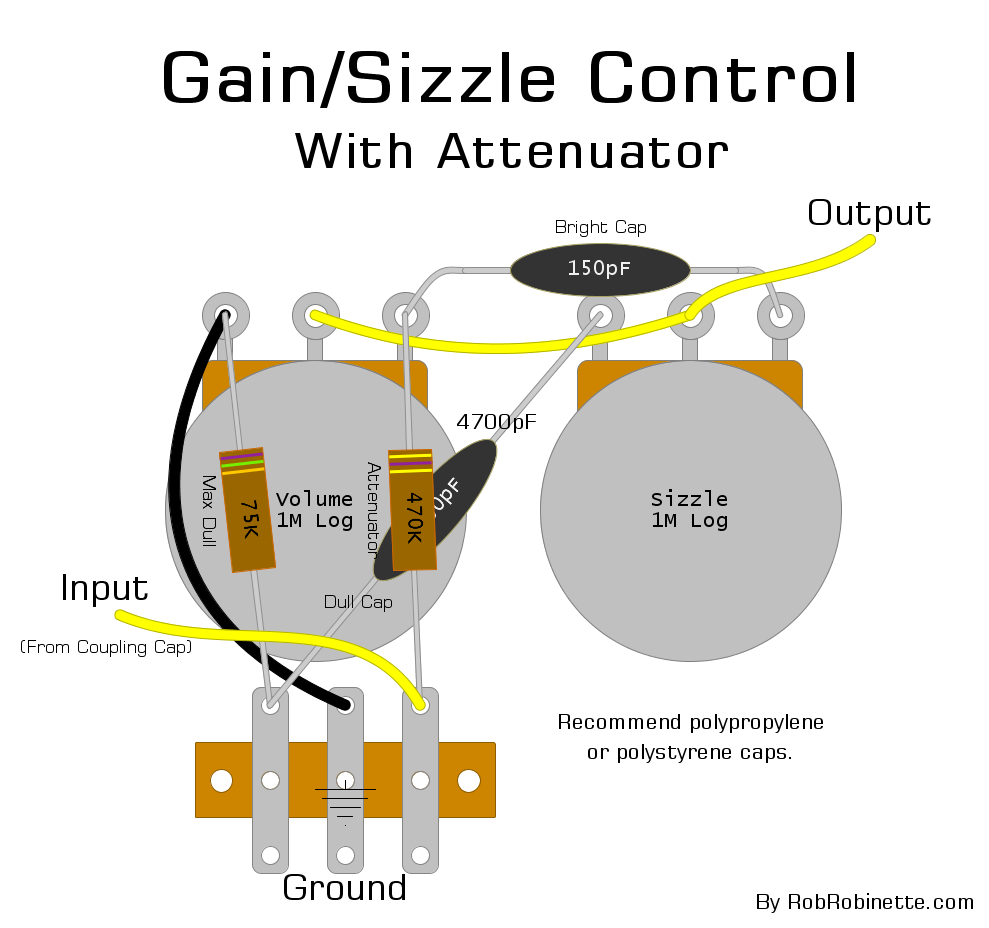
We have the option of bypassing the Attenuator Resistor with the Bright Cap to create a "treble peaker" and brighten the tone and add more sizzle. We move the Bright Cap input from the output of the Attenuator Resistor to the input of the resistor.
Note: The Gain/Sizzle Control must have a coupling cap between itself and a tube plate. It cannot function as a coupling cap like the Fender/Marshall/Vox TMB tone stack.
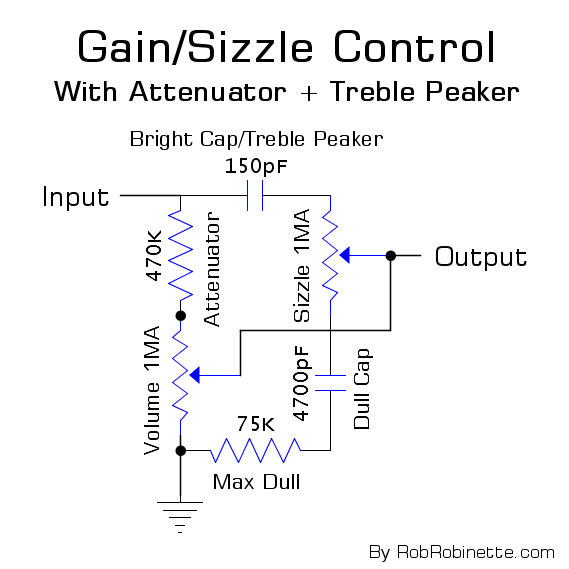
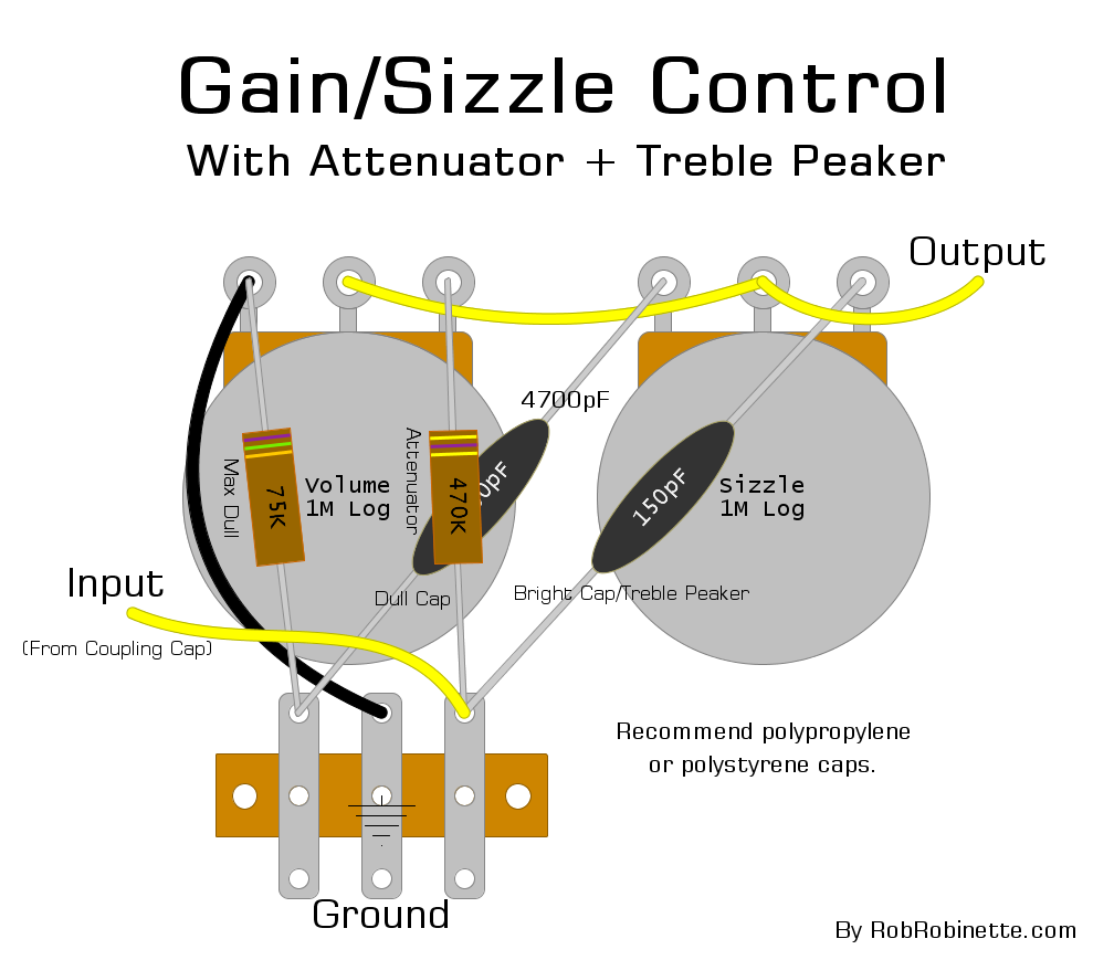
Note the change in the Bright Cap.
Run 6V6 Power Tubes in a 6L6 Amp
Running 6V6 power tubes in an amp designed for 6L6's will cut your output and offer up a different tone and usually more power tube distortion.
If your amp has a multi-tap output transformer (and all amps designed to run 6V6 and 6L6 should have them) most of the output tranny impedance mismatch can be handled by using a one step higher speaker impedance setting -- if your amp is designed for 6L6 then set the impedance selector to 8 ohms with a 16 ohm speaker or set to 4 ohms with an 8 ohm speaker.
You may need to lower your amp's B+ voltage so you don't burn up the 6V6 tubes. You can do this by simply installing a 5R4 (less sag) or 5Y3 (more sag) rectifier tube. If your amp has a solid state rectifier then use the JJ6V6S which has a 500v plate voltage limit.
You may also need to adjust the bias after installing the 6V6 tubes. If your bias is not adjustable it will probably be OK with 6V6's but watch the power tubes for red plating at first power up and measure the bias to see where they are running.
Run 6L6 Power Tubes In 6V6 Amps
You can get a different tone from many small bottle amps by installing 6L6 power tubes. But typically the power and output transformers can't supply all the extra current needed to actually get much more volume at the speaker. Running 6L6 tubes will stress the transformers so I don't recommend it but if you want to give it a try then you should make a change to the speaker load to compensate for the different power tube impedance. Just use a 4 ohm speaker for an amp with an 8 ohm secondary, or an 8 ohm speaker with a 16 ohm secondary.
Keep an eye on your power transformer's temperature when running the big power tubes but be careful because the transformer can get hot enough to burn your fingers. I use an infra red no-touch thermometer to monitor amp component temperatures. Take a measurement with the normal 6V6 tubes so you have a baseline temp to compare to how hot it gets with the big tubes.
Replacing a GZ34 tube rectifier with a solid state rectifier like the plug-n-play Weber WS1 Copper Cap will supply the amp with a little more voltage and current to better drive the big 6L6 tubes.
You will probably need to turn up the bias to get the most from your 6L6 tubes. See this to measure and adjust the bias.
Run 2 Power Tubes in a 4 Power Tube Amp
Many push-pull amps designed to run 4 power tubes can be run with 2 power tubes to cut the output power in half. But since the output transformer was designed to load the current put out by 4 power tubes we need to make an adjustment on the speaker end to load 2 tubes properly. Since 2 power tubes put out half the current of 4 tubes we need to double the speaker impedance so 2 tubes feel the same load as when 4 tubes are used. For example your amp is designed to run an 8 ohm speaker with 4 tubes like the AB763 Blackface Single Showman so it will need a 16 ohm speaker when run with 2 power tubes. If your amp has a 4 ohm secondary use an 8 ohm speaker and with a 2 ohm secondary use a 4 ohm speaker.
To run two power tubes you pull the two outside power tubes, which in the Twin Reverb are V7 and V10. In the Single and Dual Showman the outside power tubes are V5 and V8.
The plate voltage will be higher with only two tubes pulling current through the power supply so you may need to adjust the amp's bias. See this to measure and adjust the bias.
Run 2 6V6 Power Tubes in a 4x6L6 Amp
As stated above we need to up the speaker impedance when substituting 6V6 tubes in a 6L6 amp and we also need to up the impedance when running only 2 power tubes in a 4 tube amp so we need to take two steps up in speaker impedance to run 2 6V6 power tubes in an amp designed for 4 6L6 tubes. For an amp with a 2 ohm secondary we would need an 8 ohm speaker, a 4 ohm secondary needs a 16 ohm speaker and an 8 ohm secondary would need 32 ohms of speaker load (two 16 ohm speakers wired in series). For example, the Fender Twin Reverb has a 4 ohm output transformer secondary. It has two 8 ohm speakers wired in parallel to give the transformer its needed 4 ohm load. With two 6V6 tubes the amp will need a 16 ohm load which can be done by simply wiring the two speakers in series.
You must consider the power tube plate voltage when running 2 6V6 tubes. With only two small power tubes pulling current through the power supply all the voltages in the amp will be higher than normal. JJ 6V6S power tubes are good for 500 plate volts so they can handle the Twin Reverb's voltage but for normal 6V6 tubes you must do something to lower the plate voltage to keep from frying them. For amps with tube rectifiers you can plug in a lower rated rectifier like the 5R4 (less sag) or 5Y3 (more sag) to bring down the voltage. For amps with solid state rectifiers like the Twin Reverb and Single and Dual Showman you can plug the amp into a bucking transformer or variac and turn down the amp's input voltage. A bucking transformer at its lowest setting may also do the job.
To run two power tubes you pull the two outside power tubes, which in the Twin Reverb are V7 and V10. In the Single and Dual Showman the outside power tubes are V5 and V8 (tube numbering starts with the first preamp tube on the far right).
You will probably need to adjust the bias when running two 6V6 tubes. See this to measure and adjust the bias.
Phase Inverter Grid Stopper Resistor
This is a great mod for almost any amp with a cathodyne phase inverter. Add a 470KΩ 1/2 watt grid stopper resistor to the phase inverter to smooth out its overdrive. I recommend this mod be done to all 5E3 amps. It won't affect the amp's clean tone but it will keep the overdrive tone sweet when pushed hard. Actually this is a good mod for any guitar amplifier that uses a cathodyne phase inverter like the 5E3.
High volume settings or using boost, delay or reverb pedals can push the phase inverter into extreme and odd sounding 'double frequency' blocking distortion. This unpleasant distortion is the reason why the 5E3 is known as not being pedal friendly and why high gain preamp mods are not popular--any boost in preamp output can push the phase inverter into nasty distortion. By adding this resistor your amp's sweet preamp tube distortion won't get chopped up in the phase inverter. A grid stopper slows the charge rate of the phase inverter coupling cap that's upstream of the phase inverter.
If you need more to control the phase inverter's nasty distortion you can reduce the phase inverter's grid leak resistor (typically from 1M to 470k). The reduced grid leak resistor will cut the voltage drop across it by making it easier for grid current to flow to ground instead of charging the coupling cap.
So the bottom line is if the 470k grid stopper alone doesn't get you where you want to be then lowering the grid leak resistance is a good next step.
A better solution to the phase inverter distortion problem is to forget the grid stopper mod and simply replace the 1M grid leak resistor with a 1MA pot to create a PRE Phase Inverter Master Volume pot which will allow you to fine tune the grid stopper & grid leak resistor sizes to really control phase inverter distortion. By turning down the master volume by about 1/3 you do the same thing as adding a 470k grid stopper and 470k grid leak to the phase inverter. The nice thing about this master volume is when it's set a max the your amp's circuit is unchanged from stock.
Phase Inverter Grid Stopper Resistor Mod
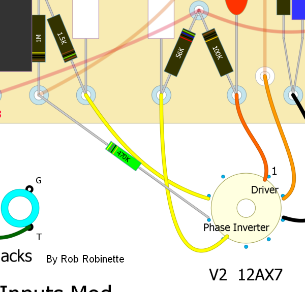
470K resistor added to the phase inverter input to reduce odd sounding double frequency phase inverter overdrive distortion.
'Sweet Pot' Variable PI Grid Stopper Resistor Mod
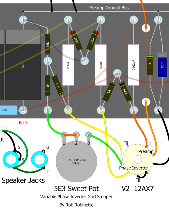
The 'Sweet Pot' allows you to vary the phase inverter's grid stopper resistor value. At 'Max Sweet Pot Volume' you have the standard 5E3 circuit with no phase inverter grid stopper resistor but you can dial out phase inverter distortion by turning down the 'Sweet Pot Volume' (counterclockwise) by adding grid stopper resistance up to 1 mega Ω.
Add Power Tube Grid Stopper Resistors
Almost all modern amps have power tube grid stopper resistors so if your amp doesn't you may want to consider adding them. Grid stoppers can help prevent blocking distortion and protect your power tubes from damage when driven hard into overdrive when grid current begins to flow.
The chance of oscillation is reduced by removing frequencies beyond human hearing when the grid stopper resistance combines with the tube's Miller capacitance to form a low pass RC (resistance/capacitance) filter.
To maximize a grid stopper's effectiveness it should to be mounted directly to the tube's grid pin. Just remove the wire from each power tube socket's pin 5 (grid) and solder a resistor directly to the grid pin and solder the wire to the other end of the resistor. You can bend the resistor's lead into a small loop to make attaching the wire easier.
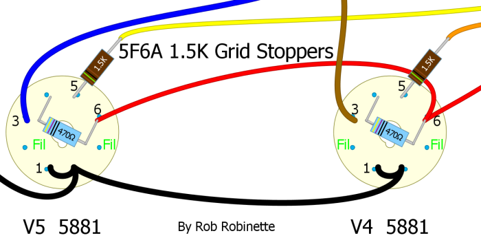
Adding grid stopper resistors will change the overdrive tone (usually for the better). The overdrive tone is changed by making positive lobe grid clipping harder and more abrupt which will sound more "modern and aggressive." A grid stopper will also alter the bias voltage shift and recovery times which affects the character of negative lobe clipping. If you want a more modern overdrive tone give them a try. For more information see Tube Guitar Amp Overdrive.
Reduce Ice Pick Highs
If your particular speakers are giving you too many 'ice pick' highs simply adding a 100pF Mica capacitor across the feedback resistor will filter out some very high freqs that can cause ice pick highs. The cap allows high freqs to go around the feedback resistor so they are used for feedback which will reduce them from the amp's output. This is a nice, subtle mod that won't screw up your amp's perfect tone. It's easy to use alligator clips to clip the cap in place temporarily to see if you like the mod. If you would like to cut even more highs than the 100pF cap, you can go all the way up to a .022uF cap to lower the filter's cutoff freq so more mid-high freqs would be cut. There's a small chance the Ice Pick Cap can induce oscillation at high volume. If that happens you can put a 4.7k resistor in series with the cap to reduce the very high frequencies that cause oscillation.

Add a Simple Line Out Jack
This, along with a headphone jack, is a common mod request. Line outs work well for feeding effects boxes but don't work that great for recording or amplification because an amp's guitar speaker does a lot of tone shaping, high frequency de-emphasis and adds speaker breakup distortion.
tdpri member mungus comments: The raw amp output sounds like crap until its passed through a guitar speaker to tone down the excessive high end - hence the need for some kind of cab simulator.
That's why using a microphone in front of the guitar amp's speaker is the most common way to feed a PA system. If you do go the microphone route use a high quality instrument microphone placed 1/2 to 1 inch from the grill cloth and about halfway between the center and edge of the speaker cone for best tone.
With the cautions out of the way here is a very simple Line Out that does capture the tone and distortion of the entire amp except for the speaker.
Line Out Jack
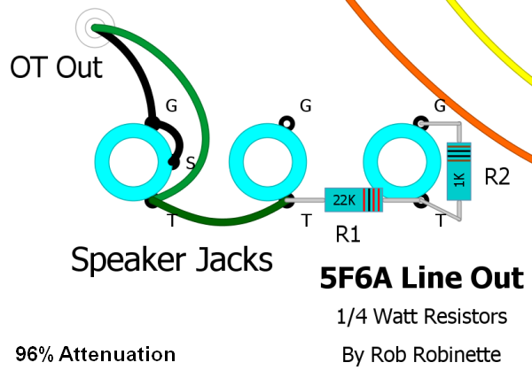
The resistors form a voltage divider and cut the speaker signal by 96%. In this layout the Switchcraft output jacks are self grounded to the chassis. If your output jacks are insulated then the Line Out's ground terminal will need to be connected to ground. The jack can be full size 1/4" or 1/8" (3.5mm) mp3 player size.
Of course the amp's output volume control will control the Line Out volume too--which brings up an important point:
WARNING: A speaker must be attached to the amp's speaker jack when using the Line Out jack to prevent output transformer damage. This tiny little circuit cannot load the transformer properly to run speakerless.
You can replace the 22k resistor with a 250k reverse audio pot (wired as a variable resistor) as a line out level (volume) control. I recommend you also add a 5k resistor between the pot and either jack to set the max volume level. Run the level at minimum volume when not using the line out.
If you are cramped for space for an additional jack you can use your amp's 'extra' speaker jack or even add a small 3.5mm (mp3 player size) jack to save room. To convert the extra speaker jack replace the tip-to-tip green wire with the 22K resistor and add the 1K resistor to the jack's tip and ground terminals.
If you install the Line Out jack near the speaker jack you can use the 22K resistor itself to make the connection from the speaker jack tip terminal to the Line Out tip terminal. Then run the 1K resistor from the Line Out jack tip terminal to your Line Out jack ground terminal. If you use metal Switchcraft style jacks that ground themselves use a star washer against the inside of the chassis to ensure a good Line Out jack ground. If your Line Out jack is insulated from the chassis then you must connect the Line Out jack's ground terminal to a suitable ground point.
The formula to calculate the % of attenuation is:
% Attenuation = (1 - R2 / (R2 + R1)) * 100
% Attenuation = (1 - 1 / (1 + 22)) * 100 = 96%
Bias Measuring Jacks
By adding four "tip jacks" and two 1 ohm 1/4 watt 1% resistors we can make it very easy to measure our amp's power tube bias without having to pull the chassis.
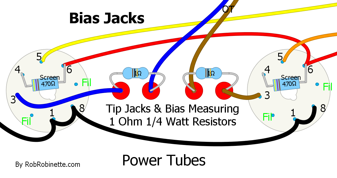
The 1 ohm resistors are placed in line with the output transformer wires that are originally connected to the power tube plates (pin 3).
All the plate current will flow through the 1 ohm resistors. If we measure the voltage drop across one of the resistors we can determine that tube's plate current. We place our meter's black probe in the tip jack nearest the tube socket. We place the red meter probe in the other tip jack (if you reverse the jacks the reading will be the same but it will be a negative number).
Note we do not measure the current using the meter's current or milliamps setting.
By using 1 ohm resistors we don't have to do any math to use Ohm's Law to calculate plate current. The meter reading will be in millivolts which will equal milliamps. For example, if we read 43 millivolts of voltage across the 1 ohm resistor that is equal to 43 milliamps of plate current.
Hoffman Tip Jacks
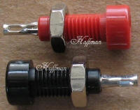
Tip Jacks have small holes just large enough to get a meter probe into. These jacks are much safer for high voltage than banana jacks. I recommend you use 4 red jacks because a black jack would suggest "ground" but all four jacks will have very high voltage on them. Get your Hoffman Tip Jacks here.
Measure the voltage from the tip jack closest to the tube socket to the chassis and you get the plate voltage. With plate current and plate voltage we can calculate plate dissipation (bias) using my Bias Calculator.
The 1 ohm resistors are only dissipating 2 milliwatts of power with 45 milliamps of current so a 1/4 watt resistor is overkill. Of course you can always use a higher watt rated resistor if you like. The closer to 1 ohm the resistors are, the more accurate our measurements so I recommend using 1% rated resistors.
Simulate Tube Rectifier Voltage Drop and Sag Using a Solid State Rectifier and Sag Resistor
Voltage drop is the amp's no signal voltage drop caused by the rectifier. A solid state rectifier will only drop about 1.4 volts per diode used so its drop is usually 3 to 6 volts. A tube rectifier will drop more voltage than a solid state rectifier. A GZ34 will drop 10 to 15 volts more than solid state and the 5Y3 will drop around 60v more than solid state.
Voltage sag is the dynamic voltage drop that varies with current demand and causes compression of loud and quiet notes.
If your amp has a solid state rectifier we can simulate tube style voltage drop and sag by adding a sag resistor to the rectifier's output. To determine the value and watt rating of the sag resistor we need to know what type of tube rectifier we're trying to emulate (how much voltage drop do we want) and how much B+ current will flow through the resistor. You can get a good estimation of B+ current with this online calculator.
Here's a chart from 300guitars.com showing different rectifier voltage drops:
So if we want to simulate a 5V4 we need to drop about 25 volts. We'll say our amp's idle B+ current is 174 milliamps or .174 amps.
The equation to determine the amount of resistance in ohms to drop a voltage is:
Resistor size = Volts to drop / Amp B+ current = 25 volt drop / .174 amps = 143 ohms
We can round down to the standard resistor size of 130 ohms. The voltage drop from a tube rectifier is not linear and there's less sag at high demand so I recommend you always round down to the next standard resistor size.
The equation to determine power in watts is: Watts = Volts * Amps = 25 volt drop * .174 milliamps = 4.35 watts
We need to approximately double the watts to cover ripple current and to ensure the long term reliability of the resistor so I would use a 130 ohm 10 watt sag resistor to simulate a 5V4 tube rectifier. The sag resistor would go between the solid state rectifier's output and first filter capacitor.
Lower the B+1 Voltage
Modern wall voltages are higher than they were back in the 50's when Fender tweed amps were designed so today's wall voltages can increase your B+ by over 30 volts. Lowering your amp's B+ voltage can lengthen tube life and soften its tone. You can do this with a rectifier tube swap. Here's a chart from 300guitars.com showing the different voltage drops:
My Rectifier Tube Comparison
| Solid State | JJ GZ34S | GT 5U4 | JJ 5U4GB | |
| AC in to Rectifier | 682v AC | 678 | 677 | 677 |
| B+ | 434v DC | 416 | 392 | 384 |
| Drop from Solid State | - | 18v | 42 | 50 |
| V2B Plate | 252v DC | 238 | 226 | 221 |
| V2A Plate | 206v DC | 195 | 185 | 181 |
| V1B Plate | 207v DC | 197 | 188 | 184 |
| V1A Plate | 201v DC | 190 | 182 | 177 |
| Power Tube Plate to Cathode V | 403v DC | 379 | 360 | 351 |
| Cathode Voltage Drop | 32.2v | 30.3 | 28.6 | 27.7 |
| 6L6GC Cathode Bias Output @ 4ohms | 17.9 watts | 15.5 watts | ||
| 6L6GC Fixed Bias Output @ 4ohms | 32.5 watts | 30.8 watts |
Notes: Wall voltage measured at 122.3 volts rms. Power Transformer rated at 330v-0-330v. No power tube cathode resistor bypass capacitor was installed.
My 5E3P Proluxe (fixed bias 6L6) power transformer is rated at 330-0-330 volts but actually puts out 341-0-341 under idle load and an input wall voltage of 122.3v. With that I get 434 volts B+ with a solid state 1N4007 diode rectifier and 416v B+ with a JJ GZ34S rectifier tube (18v drop). I tried a Groove Tubes 5U4G to get down to a more 'vintage' B+ voltage. It gave me a 392v B+ (42v drop from solid state). A JJ 5U4GB dropped the B+ to 384 volts (50v drop) which is low enough to run 6V6 tubes in my 5E3P in both fixed and cathode bias modes. A standard 5Y3 would also lower the voltage enough for 6V6 tubes in the 5E3P and 5F6A.
It is also possible to drop your B+ voltage using a dropping resistor before your first filter capacitor but keep in mind the resistor will increase power supply voltage sag. To take 10 volts off the 5F6A's B+ you can use a 3 or 5 watt 62 ohm resistor. A standard 5F6A pulls about 167 milliamps (.167 amps) of B+ current so to determine the size of the resistor use these equations:
Desired voltage drop / amps = resistor ohms
10 volt drop / 0.167 amps = 60 ohm dropping resistor (62 ohms is closest standard resistor size)
amps * voltage = watts of dissipation
0.167 amps * 10 volts = 1.67 watts
So a 62 ohm 3 watt resistor will drop your B+ around 10 volts. You could also use two 120 ohm 2 watt resistors in parallel to get the same voltage drop because they are the equivalent of a single 60 ohm 4 watt resistor.
To find the B+ current for other amplifiers use this easy to use excellent power transformer calculator.
For cathode biased amps we can install Zener diodes on the power transformer center tap to lower the B+ voltage. The power transformer center tap is the return path for all the B+ current so it's a convenient location for controlling an amps voltage. Zener diodes do not cause voltage sag, they cut the voltage and hold it there. You can also use a resistor on the center tap but the voltage will sag with current draw--this may or may not be desirable.
For a single Zener diode solder a ring terminal to its cathode (striped) end and bolt it to your chassis ground bolt. Solder the power transformer center tap wire to the diode's other end. For 10 volt Zeners a 5 watt rating is all that is needed for most amps. You can also string together Zeners to drop more voltage:
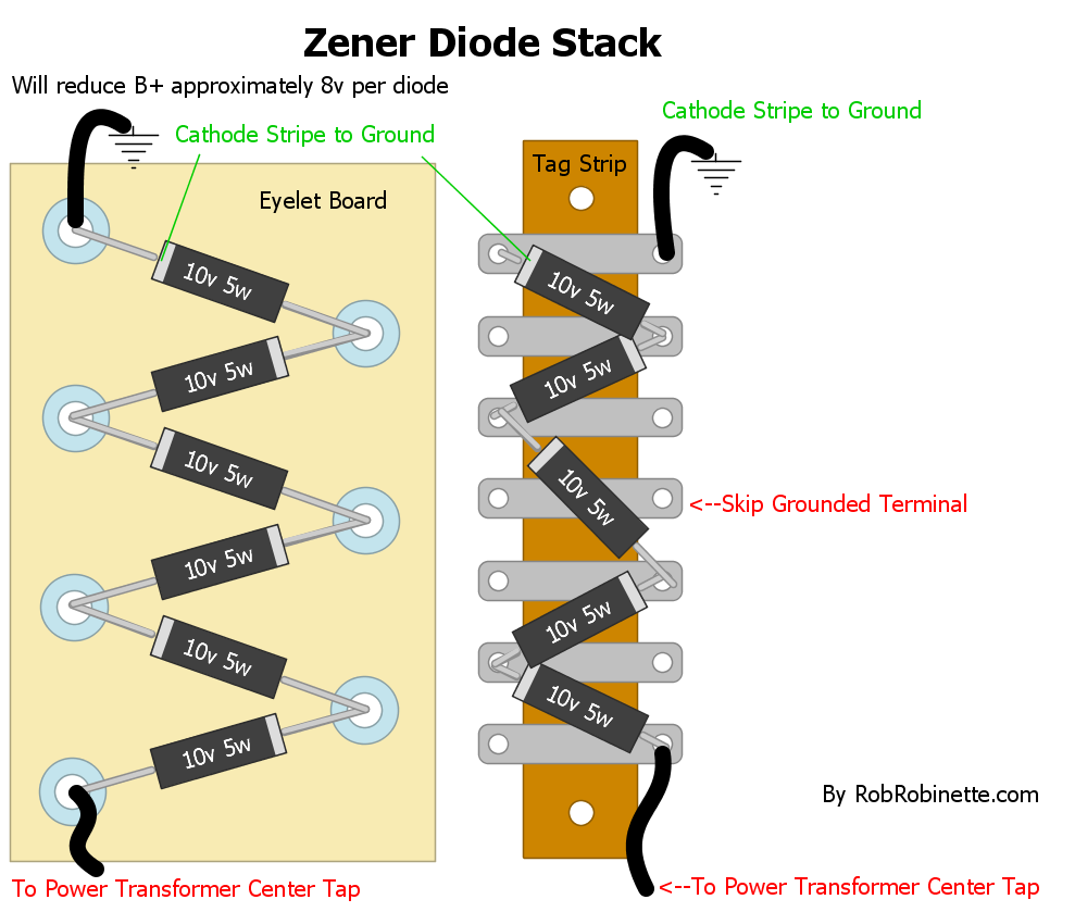
The diode stripe marks the cathode and negative end of the diode. The other end is the + anode.
For fixed-bias amps we need to consider the fixed bias circuit. We can't use the center tap as above because it will affect the fixed bias circuit because negative voltage bias current flows the opposite direction and doesn't get cut by the Zener. The easiest solution is to move the bias circuit ground from the chassis or power amp ground to upstream of the Zener(s) on the center tap.
Another solution is to connect the Zener string between the rectifier and the amp circuit, just like a sag resistor. Install the Zeners with their stripe (cathode) toward the rectifier, the other end (anode) toward the first filter cap. Since neither end of the Zener is grounded we can't bolt the Zener to the chassis for cooling so be conservative with your Zener watt rating--I wouldn't go above 10v for a 5 watt rated Zener.
One other option to lower B+ voltage is to build an inexpensive 'bucking' transformer to lower your wall AC voltage which will lower all the AC and DC voltages in your amp including the tube heater circuits.
Lower Your 6.3V Heater Voltage
Most tubes list the required heater voltage as 6.3 volts +/- 10% or 5.7 to 6.9v. Running the heater voltage above or below 6.3 volts can shorten the life of your preamp and power tubes.
Tube Life Vs. Heater Voltage

If you want long tube life then feed them 6.3 volts. Most tubes list their heater limits as 6.3v +/- 10% or 90 to 110% on the chart. 90% = 5.7v and 110% = 6.9v.
My amp's heater circuit measures 6.8v so it's close to the max allowed. Dropping a half of a volt would be perfect to get the standard 6.3 volts. My 5F6A draws 2.7 amps of 6.3v heater current using 6L6GC and 5881 power tubes (3.9 amps with EL34's) so we can use this equation to calculate what resistors to use to lower our heater voltage. You can place the resistors on the V5 power tube's pins 2 & 7 and attach the inbound heater wires (from transformer or pilot light) to the resistors. I used a small 2 inch x 1.5 inch perf board to mount the resistors.
Desired voltage drop / amps = resistor ohms
.5 volt drop / 2.7 amps = 0.19 ohm dropping resistor
We want to keep the voltage balanced on each heater pin to reduce 60Hz hum so we need to use two resistors, one on each pin
We divide the 0.19 ohm by 2 to get 0.095 ohm (I rounded up to 0.1 ohm)
Note: These same resistors would drop .78v when using EL34 power tubes (3.9 amps * .2 ohms = .78v)
amps * voltage = watts of dissipation
2.7 amps * .5 volts = 1.35 watts so to be safe the two resistors should be rated at 2 watts or more each.
So we would install two 0.1 ohm 3 watt wire wound resistors on V5's heater pins (2 & 7) and connect the inbound wire (from the power transformer or pilot light) to the resistors. I like to use a terminal strip to support the other ends of the resistors. These two resistors will drop the heater voltage by 0.5 volt. These types of resistors are available at http://www.mouser.com/ for about 50 cents a piece.
Another solution to high heater voltage is a bucking transformer which will lower all amp voltages. I run all my vintage amps with a bucking transformer to get all their voltages down to vintage levels.
Humdinger Heater Hum Pot
The Humdinger is an adjustable heater artificial ground. A 100 or 250 ohm, 1 watt or greater linear pot is used to adjust the resistance value between ground reference and the two heater wires to even out their voltage and minimize 60Hz heater hum. You simply adjust the pot by ear for least hum. If you don't notice a change in hum when adjusting the Humdinger then just set it in the middle of the pot travel to equalize the resistance for each heater wire. Remove your current 6.3v center tap before installing a Humdinger.
You can connect the Humdinger to the heater wires anywhere along the heater wire chain. You can use the pilot light or tie it into any one of the tubes' heater terminals.
For cathode biased amps you can connect the Humdinger's ground wire to a power tube socket cathode pin (pin 8) or to the hot side of the cathode resistor (as shown in the next section) to elevate the heater reference voltage. You can also create an elevated voltage source by using a voltage divider (see next section). A voltage elevated Humdinger can eliminate more heater hum than any other type of heater real or artificial center tap.
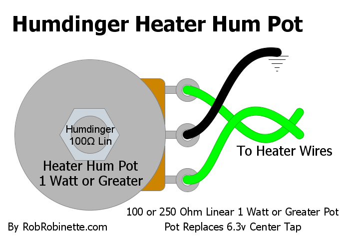
250 ohm linear pot is used to balance the voltage on the two heater wires for minimum hum. A 100 ohm linear pot will work fine too. The pot needs to be rated at 1 watt or higher. This $3 100 ohm, 5 watt pot is perfect as a humdinger. Instead of connecting the center terminal to ground as shown, connecting it to a cathode biased amp's cathode resistor will elevate the center tap and reduce hum.
Heater Elevation Using a Voltage Divider
This is a good mod for any amp with a tube cathode follower or other triode with high voltage on the cathode. A simple two resistor voltage divider can be used to generate a 40 to 65 volt elevated heater ground reference. Elevating the heater voltage reduces the voltage between the heater filaments and the surrounding cathode. Most 12A*7 tubes have a 200v heater filament-to-cathode max voltage so many cathode followers push or exceed that value. My 5F6A Bassman's cathode follower has a 188v difference between the heater voltage and cathode voltage. Elevating the heater 40 to 65 volts will reduce the voltage difference which can make the cathode follower tube last longer and it can also reduce heater hum.
This voltage divider elevated ground reference can be used with a 6.3v center tap. Just connect the power transformer's 6.3v center tap lead to the voltage divider resistor junction.
This voltage divider can also be used with an artificial center tap. Connect the artificial center tap to the voltage divider instead of to ground.
This voltage divider can also be used with the above Humdinger pot by connecting the Humdinger wiper (center terminal) to the elevated voltage divider instead of to ground.
I like to use B+1 or B+2 voltage for the divider power source. If your amp has or needs a 220k bleeder resistor across a filter cap you can install a voltage divider made up of a 200k 2 watt and 33k 1/2 watt resistor in its place. This resistor combination will reduce its input voltage by 86% (450v - 86% = 64v). The 200k resistor will burn .75 watt so a 2 watt resistor is plenty big. The 33k resistor only burns .13 watts so 1/2 watt is fine. A 10uF 100V filter cap across the 33k resistor will keep the center tap hum free. You can use up to a 470k upper resistor to adjust the voltage to your liking.
Heater Elevation Voltage Divider & Bleeder Resistor
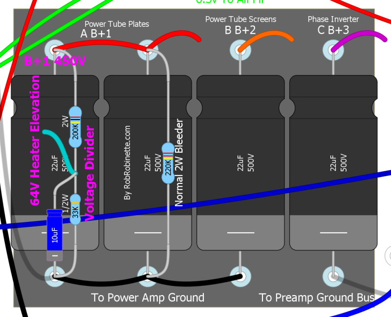
A voltage divider across this filter cap takes in 450 volts and puts out 64 volts at the resistor junction. The resistors will also bleed residual voltage from the cap when the amp is shut down. A 10uF 100V filter cap across the 33k (lower) resistor will keep the center tap hum free. Connect the divider voltage at the resistor junction to either: 1. Power transformer 6.3v center tap. 2. 6.3v artificial center tap. 3. Humdinger pot wiper.
For an amp with 360 volts a 180k 2W and 39k 1/2W divider will supply 64 volts at the divider junction.
The formula to calculate the output voltage at the resistor junction is:
Input Voltage * (Resistor 2 / (Resistor 1 + Resistor 2)) = Output Voltage
Resistor 1 is connected to the power supply, Resistor 2 is connected to ground. For the divider above:
450v * (33 / (200 + 33)) = 64 volts
A 10uF 100V filter cap across the 33k (lower) resistor will keep the center tap hum free.
You can also install the voltage divider on a power tube socket and tap B+2 screen supply voltage and ground at the socket as shown below:
Artificial Center Tap & Heater Elevation Voltage Divider On Power Tube Socket
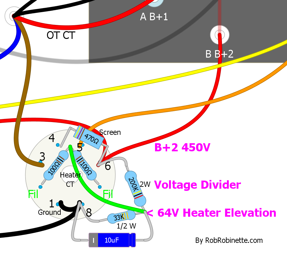
A heater artificial center tap is shown connecting a power tube's filament pins 2 and 7 with two 100 ohm 1/2 watt resistors. The junction of the two resistors is connected to the heater elevation voltage divider which has 64 volts at its resistor junction. You can actually connect the apex of all four resistors and delete the green jumper wire if you like. Do not use this divider on cathode biased power tubes. This circuit must have a ground connection to pin 8, not a cathode resistor.
For the amp above with 450 volts of B+2 (screen) power is tapped off of pin 6. The 200k 2 watt / 33k 1/2 watt voltage divider drops the voltage at the junction by 86% down to 64 volts.
Notes:
You must tap the B+2 voltage on the input side of the screen resistor--do not tap the output side of a screen resistor because the reference voltage will fluctuate.
You can tie all four resistors together at their junctions to form a resistor "pyramid."
To reduce the clutter on one power tube socket you can put the voltage divider resistors on one power tube socket and place the artificial center tap resistors on the other power tube socket and connect the apex of the two sets of resistors with a wire.
DC Preamp Tube Heat Power Supply Using 6.3VAC
Using well filtered DC for heater power in the first preamp stages can significantly reduce heater hum in high gain amplifiers and phono preamps. This circuit uses 6.3v AC for its input and puts out 6.3v DC. You can power most of your tubes with 6.3v AC but power the first two preamp tubes--where noise really matters--with 6.3v DC.
The circuit takes 6.3 volts from the power transformer 6.3v secondary (or dedicated 6.3v transformer) and rectifies it with a bridge rectifier rated at 1 amp or more. The 512-GBU4M Bridge Rectifier ($1.30 at Mouser.com) is rated at 4 amps but must be bolted to the chassis for cooling to run at 4 amps. If pulling 1 amp (3 12A*7 tubes) or less through this rectifier we can use circuit board mounting of the rectifier (standing up as shown in the layout below).
If your 6.3v secondary does not have a center tap then resistors R1 and R2 form an artificial center tap. If your 6.3v secondary already has a center tap (real or artificial) then use it and delete R1 and R2.
Capacitors C1, C2 & C3 are filter caps which remove AC ripple. Capacitors C4 & C5 form an AC ground reference that splits the 6.3 volts DC output to +3.15v and -3.15v. This is done to reduce the voltage difference between the tube cathode and heater filament to reduce heater hum. The C4/C5 ground reference needs to use the same ground reference as the 6.3v center tap (real or artificial).
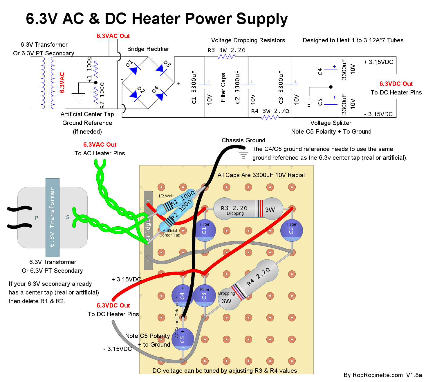
The circuit is designed to heat 1 to 3 12A*7 preamp tubes at a total of 1 amp or less. If your 6.3v secondary already has a real or artificial center tap then delete R1 & R2. All caps are 3300uF 10v radial electrolytics. Bridge rectifier is a 4 amp rated 512-GBU4M ($1.30 at Mouser.com). The C4/C5 ground reference needs to use the same ground reference as the 6.3v center tap (real or artificial).
The output DC voltage is affected by the AC input voltage. It is very common for "6.3v" secondaries to run higher than spec, sometimes 6.8 volts or higher. If you need to lower the AC voltage then use this technique to lower the 6.3v AC supply voltage.
You can fine tune just the DC output voltage by adjusting the value of R3 or R4. To lower DC voltage increase the value of R3. To raise DC voltage decrease the value of R4. The amount of resistor adjustment is dependent upon how much DC current is being used by your tube heaters. A typical 12A*7 tube uses 0.3A of heater current so two tubes will pull 0.6A and three will pull 0.9A.
The formula for voltage change is: Desired voltage change / amps = resistor ohms
For example, you have 6.8 DC volts supplying two preamp tubes and want to drop it to 6.3 volts: 0.5 volt drop / 0.6 amps = 0.8 ohm of additional resistance added to R3, 2.2 ohms + 0.8 ohm = 3 ohm resistor for R3. Instead of replacing R3 with a 3 ohm 3 watt resistor you can instead insert a 0.8 ohm 1 watt resistor in place of the red wire running above R4 and leave R3 at 2.2 ohms. Mouser.com sells odd value resistors like this.
Try to keep R3 & R4 values as close as possible to preserve voltage balance.
If you are powering one 12A*7 tube (0.3A) then each ohm of resistance added to R3 will drop the output voltage by 0.3 volts.
With two 12A*7 tubes (0.6A) each ohm of resistance added will drop the output voltage by 0.6 volts.
With three 12A*7 tubes (0.9A) each ohm will drop 0.9 volts.
Tube Life And Heater Voltage
If you want long tube life then feed them 6.3 volts. Most tubes list their heater limits as 6.3v +/- 10% or 90 to 110% on the chart. 90% = 5.7v and 110% = 6.9v
Bill of Materials
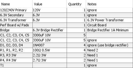
I recommend the use of a 4 amp or higher rated bridge rectifier such as this 4 amp 512-GBU4M available at Mouser.com for $1.30.
Standby Switch 'Pop Reduction' and Current Surge Protection
One modification I highly recommend on amps with Standby Switches is placing a Surge Resistor across the Standby Switch terminals. It will quiet or eliminate the Standby Switch 'pop' by allowing a small current to flow around the Standby Switch to charge the Filter Capacitors. This prevents an inrush current surge when you close the Standby Switch. It also helps control the fly-back voltage spike from a choke when the Standby Switch is opened.
With this resistor in place you should place the Standby Switch is in the standby position before powering up the amp. Turn on the Power Switch then wait around 15 seconds for the tube heaters to come up to temp and for the pop resistor to charge the filter caps enough to prevent a current inrush which is what causes the switch pop. Preventing current inrush should also make your filter caps last longer.
I like to use a 220k 1watt Surge Resistor. Adding the resistor eliminated all Standby Switch pop from my 5E3 amp.
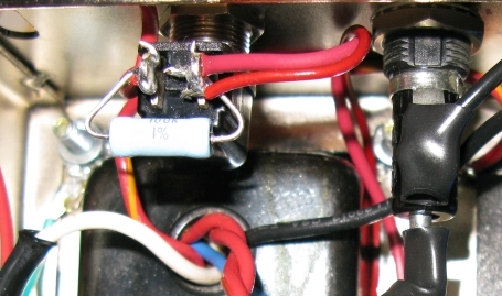
Pop Resistor across the Standby Switch
You can also use the "Power Switch Pop" mod in the next section to eliminate Standby Switch Pop.
Power Switch Pop Elimination
This mod will eliminate switch pop when turning off the amp. We bridge the two switch contacts with a 0.05uF (or 0.047uF) 1000v ceramic disc capacitor ($2) in series with a 470 ohm 1/2 watt resistor which creates a snubber. This mod will also reduce switch arcing and extend the life of the switch
LED Pilot Light
This simple circuit powers an LED from the 6.3v heater wires.
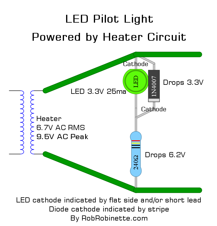
Just use any 1N4001 to 1N4007 diode, an LED and a 240 to 1000 ohm 1/2 watt (or higher watt rating) resistor connected across the heater wires. Note the LED and diode are lined up with their cathodes opposite one another. The diode has a stripe on its cathode end, the LED's flat side and/or shorter wire lead is the cathode so wire the LED's short wire to the diode's non-striped end. 6.7VAC RMS and 9.5 peak volts are used due to typical higher than spec mains voltage.
The diode limits the LED's reverse voltage to 1.7v. The resistor drops excess voltage. The voltage drop of typical LEDs runs from about 1.8v to 3.3v and varies by the color of the LED. A typical red LED drops about 1.8 volts and rises as the light frequency increases. Blue LEDs drop around 3.3 volts. You can reduce the value of the resistor to brighten the LED if it appears dim. A higher resistor value will dim the LED.
Here's how to calculate the exact values needed for your particular LED:
Find your LED's voltage and current requirements. 3.3v and 25ma is typical.
We start with converting your actual heater voltage in RMS to peak voltage. Your volt meter shows RMS voltage. Typical real world heater voltage is around 6.7 AC volts RMS * 1.414 = 9.5 volts peak.
Calculate excess voltage: 9.5 volts - the LED voltage drop of 3.3v = 6.2v
Calculate resistor value needed to drop excess voltage: excess voltage / led current = 6.2v / .025 amps = 248 ohm resistor (240 ohm is closest standard value)
Calculate resistor watt value: (LED current)^2 * 240 ohms = .025 * .025 * 240 = .15 watts so a 1/2 watt resistor will have some breathing room.
This LED would probably light up nicely with any resistor value between 240 to 1000 ohms.
Using the Ground Switch Hole for Mods
It's common practice to use the empty chassis hole for the unused 'Ground Switch' for modification pots and switches. Be aware that with all the 120v AC stuff nearby (fuse, pilot light, ON/OFF switch) that it's very easy to pick up AC line noise and 60Hz hum there. I recommend you use shielded coax for any signal wire that runs to and from that location. The coax shield should only be grounded at one end to prevent forming a ground loop. I like RG174 coax for single wire runs but shielded microphone wire has 4 conductors which works well when you need to run shielded wires to and from a pot.
Add a Soft Start Inrush Current Limiter
This $1 inrush current limiting NTC thermistor is used in modern Fender amplifiers to give the rectifier and power supply components a "soft start". It limits the the cold start inrush current as the rectifier charges the filter (reservoir) caps. It is placed between the power cord's neutral line and power transformer primary. It's rated for both 120 and 240 volt mains at 220 ohms (cold resistance) and 2 amps. When cold the thermistor's 220 ohms of resistance limits inrush current to 0.6 amps with 125v mains and 1.2 amps for 240 volt mains. As the thermistor warms up its resistance drops.
Fender 57 Deluxe Power Input
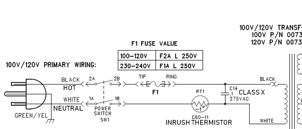
The 57 Deluxe power circuit meets all modern legal and electrical code requirements. "RT1" is the inrush current limiting thermistor placed in the white neutral line. C14 is a .1uF 275V X Class Capacitor for line noise reduction placed across the hot and neutral line. F1 is the typical 2 amp slow blow mains fuse (1 amp for 240 volt mains). The SW1 Power Switch is a DPST switch that switches both the hot and neutral power cord wires.
Protection Mods
These amp protection mods were detailed in a series of articles in Premier Guitar by R.G. Keen.
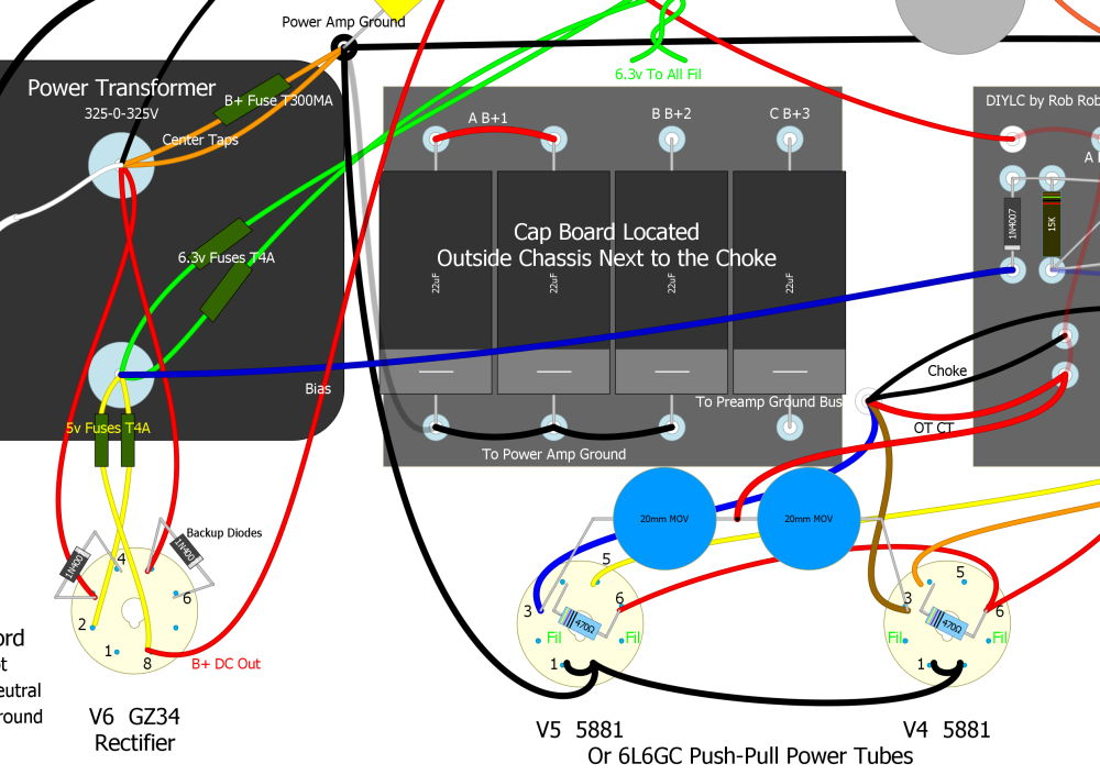
Power transformer inline pigtail fuses, soft fail rectifier backup diodes on the rectifier tube socket, and spike eating MOV's added between the power tube plates (pin 3) and output transformer center tap. 5v and 6.3v heater fuses are standard 250v. If you don't want to install in-line fuses there are circuit board mounted fuse holders available.
Fender guitar amp fuses are normally MDL type "slow blow" or "time delay" 1/4 inch (6mm) wide by 1 1/4 inch (30mm) long.
Amp fuses suggested by R.G. Keen: 300 to 500 milliamp slow blow fuse for the 5F6A to the power transformer high voltage center tap (B+ Fuse). 200 to 300 milliamp for a 5E3. 250v 4 amp slow blow fuses added to each 6.3v heater line (2 parallel fuses = 8 amp limit). If your amp uses an artificial center tap then a single 4 amp slow blow fuse in either of the 6.3v lines is all you need.
A single 250v 4 amp slow blow fuse added to either of the rectifier's 5v heater line will protect the circuit (ignore the second fuse in the layout, it's not needed). I don't recommend a fuse on the power transformer's bias tap because if it blows the power tubes will run away with max current and burn up. I highly recommend you at least install the B+ fuse to protect the power transformer.
Marshall likes to use a 500ma fast blow fuse in each of the high voltage secondary wires (not shown above) in their 50 watt amps, and 1 amp fuses in their 100 watt models. Just insert them between the power transformer and rectifier tube. An amp with a pair of 6V6 power tubes would use a 300ma fast blow fuse.
If your amp has a cathode follower and are concerned about cathode follower grid-to-cathode arcing at startup you can connect this 120v neon bulb between the cathode followers grid and cathode. You can connect the bulb directly to the tube socket. You can also use a 10k 1/2 watt resistor in series with a 1N4007 diode instead of the bulb. Connect the diode stripe (cathode) to pin 8 (cathode). If you start blowing cathode follower tubes then this is the fix you need.
A cathode follower also puts a strain on the cathode-to-heater voltage limit. It's usually around 100v and a typical cathode follower has around 180v on the cathode and the heater filaments are referenced to chassis ground for a 180v difference. Elevating the heater voltage to around 70v will greatly reduce the strain on the cathode follower heater insulation and also reduce 60Hz heater hum. Creating a voltage divider of the B+2 power node can be done with two resistors and a cap. See the JCM800 6V6 layout for an example.
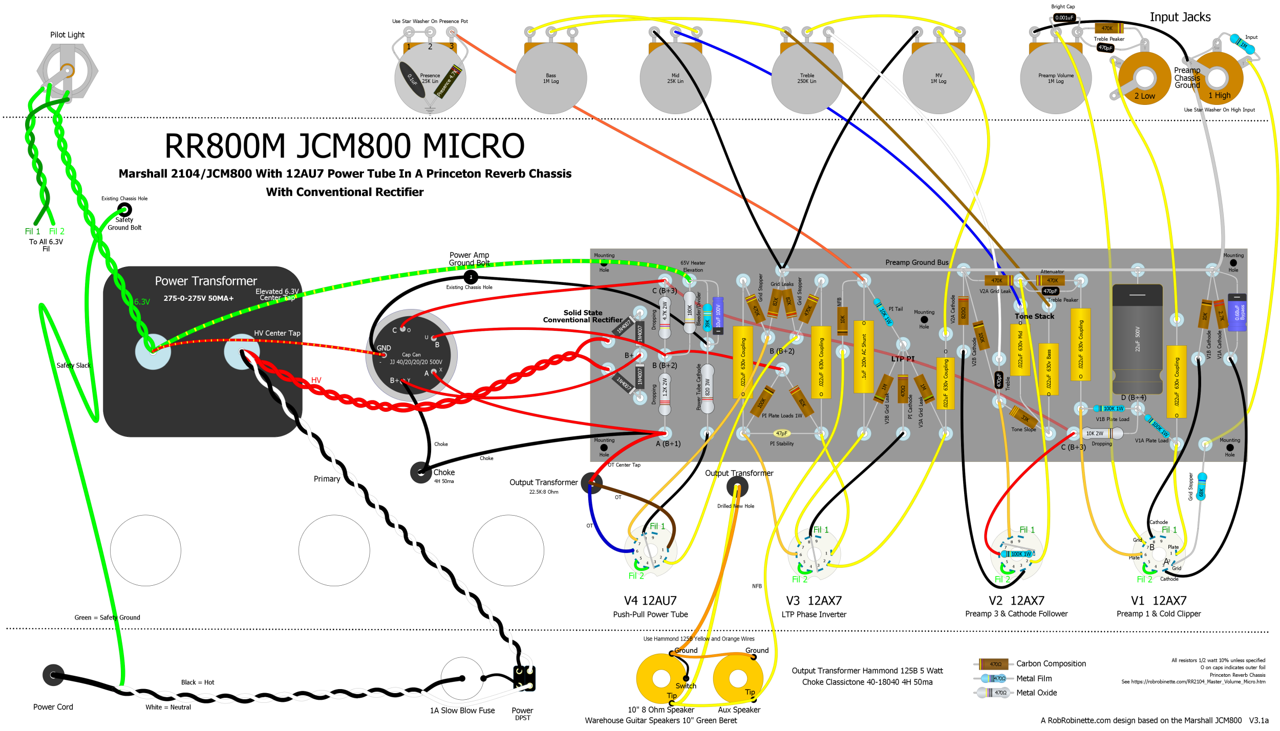
Voltage spike suppressing 20mm MOV's (metal oxide varistor) installed between the power tube socket plate pins (pin3) and the output transformer center tap (shown at lower right in the layout above). I used 625v 1.65kv clamping TDK MOV's from Mouser.com.
All of these mods help protect your expensive power and output transformers.
Fender's Modern Version of the 5E3 Deluxe
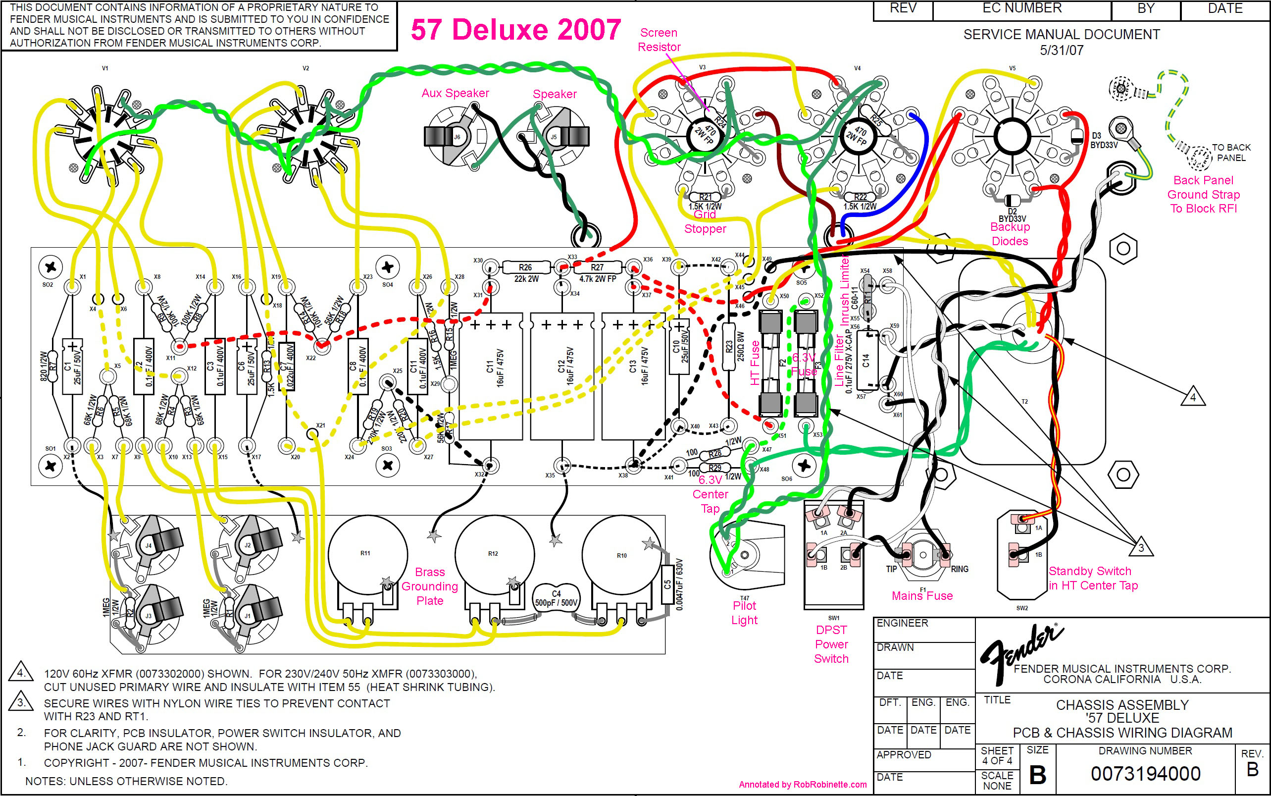
The 57 Deluxe power circuit meets all modern legal and electrical code requirements. "RT1" is the inrush current limiting thermistor (Amphenol CL-60A) placed in the white neutral line. C14 is a .1uF 275V X Class Capacitor for line noise reduction. F1 is the typical 250v 2 amp slow blow mains fuse (use 250v 1 amp fuse for 240 volt mains). The SW1 Power Switch is a DPST switch that switches both the hot and neutral power cord wires--this is required for new commercial amplifiers in the USA. Note the addition of a 6.3v heater circuit fuse and B+ fuse (250v 4amp fuse). The Standby Switch disconnects the power transformer's high tension center tap killing the B+. 470 ohm 2 watt screen resistors are added to the power tube sockets. 1400v (peak-to-peak voltage) rated BYD33V fast soft-recovery controlled avalanche rectifier backup diodes are added to the rectifier tube socket. The amp uses a metal back panel cover which is grounded to the chassis with a jumper wire (top right) to shield against RFI. Surprisingly, the amp uses an old school brass grounding plate under the controls and input jacks.
Rectifier 'Backup' Diodes
Installing two 'backup' diodes can extend the life of your rectifier tube and prevent a dying rectifier tube from frying your amplifier circuit with high voltage AC. The backup diodes pre-rectify high voltage AC from the power transformer into pulsing DC and feed it to the tube rectifier which will power the amp and give you that loved tube rectifier voltage sag. The 20 cent 1N4007 diode has a 1000v peak-to-peak or 353v RMS peak inverse voltage (PIV) rating. Fender's modern 5E3 above uses 1400v (peak-to-peak voltage) rated BYD33V fast soft-recovery controlled avalanche rectifier backup diodes. The 5Y3 rectifier tube is rated at 1400vpp PIV or 495v RMS on each plate. Having two diodes in series (one solid state and one tube) will increase the rectifier circuit's peak inverse voltage to 848v RMS which should greatly increase the rectifier tube's lifespan. You're rectifier tube should outlive your amp with these backup diodes sharing the load.
I installed two 1N4007 diodes on the rectifier socket pins 3 to 4 and pins 5 to 6. Place the diode's stripe (cathode end) on the power outflow side (pins 4 and 6). I moved the power transformer high voltage output wires from pins 4 and 6 to the unused pins 3 and 5. The AC power then flows through the diodes to the plate pins 4 and 6. The diodes are cheap insurance and I install them in all my amps.
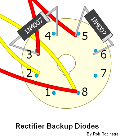
The stripe on the diode indicates polarity.
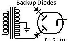
Installing backup diodes greatly increases the peak inverse voltage (PIV or reverse repetitive maximum voltage Vrrm) handling of the tube rectifier which should extend its lifespan. Should the rectifier tube fail and short out damaging AC will not enter the amplifier circuitry.
No Transformer Center Tap Hybrid Tube Rectifier
This allows you to use a transformer with no center tap with a tube rectifier by installing the 'bridge half' of a bridge rectifier to provide a current return path. Two 1N4007 diodes running from the tube plate pins to ground will do the trick. Diode polarity is important, install the diodes with their stripes to the tube plates.
Hybrid Tube Rectifier With No Center Tap + Backup Diodes
Why would anyone do this--bolt a full bridge rectifier to a tube rectifier? So you can use a transformer without a center tap, extend the life of the rectifier tube, protect the amp from hard rectifier tube failure and get a tube rectifier's vintage voltage drop and sag.
6.3v Heater Artificial Center Tap
Install a 6.3v filament heater artificial center tap (sometimes called "artificial ground"). If your power transformer did not come with a 6.3v heater center tap then you should add an 'artificial center tap' to eliminate 60Hz heater hum. It does this by balancing the voltage between the two heater wires. When each wire carries an equal AC voltage 60Hz hum will be cancelled out by twisting the heater wires together. Unbalanced voltage will allow some hum to leak out. If your power transformer does have a 6.3v center tap (usually a green & yellow wire) then I recommend you use that instead of this 'artificial center tap,' but do not use both real and artificial center taps together. Using both can cause a very noisy ground loop.
You simply connect both 6.3v green heater wires to ground through two 100ohm 1/2 watt resistors. I like to place the resistors on one of the power tube's socket as shown below.
6.3v Filament Heater Artificial Center Tap
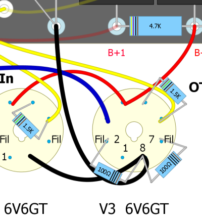
Filament heater artificial center tap consists of two 100 ohm 1/2 watt resistors connected between either one of the power tube socket's pins 2 and 7 (heater wires) and pin 8 (cathode). This works in both cathode bias amps (elevates the heater ground) or fixed bias amps (grounded cathode). Do this only on one power tube. These resistors are not required if your power transformer has a 6.3v center tap.
Add a 6" Practice Speaker to Your Amp Head
I installed an Eminence 620H 6" hemp coned speaker in my 5F6A amp head. It makes low volume practice easier and adds very little weight. Since it must be offset to the preamp side of the amp it will actually help balance the weight of the amp. Also consider offsetting the amp's carry handle one or two inches toward the heavy end (transformer end) of the chassis (would be left in picture below) to balance the amp during hand carry.
Stealth Eminence 6" 620H 20 watt Hemp Coned Practice Speaker
This is a very cool little $55 speaker. It adds very little weight to the head cab. It's mounted on the preamp side to clear the transformers. The custom lacquered tweed cab with baffle was made by John Mergili of www.mergili.com and cost only $259 delivered.
TMB Tone Stack On Pots
This is a point-to-point layout for mounting Treble Mid Bass tone stack components directly to the TMB pots.
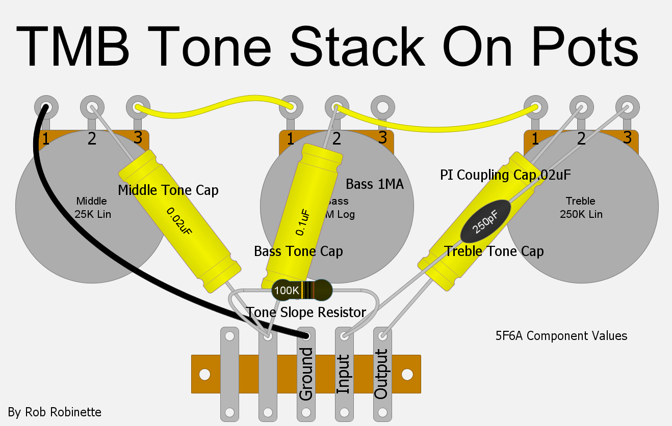
The Fender TMB tone stack mounted on the pots. A two or three terminal Terminal Strip can be used to secure the 56k Slope resistor. Click the image to see the PDF.
Fixed Mid TB Version
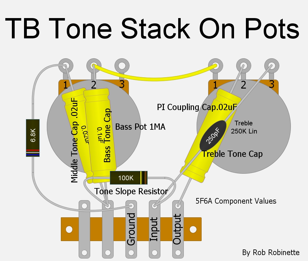
The Middle pot has been replaced with a 6.8K resistor.
Tremolo Cut Switch Mod
For amps with Fender style tremolo circuits this SPST ON/OFF mini switch completely disconnects the Tremolo circuit which will boost the guitar signal because the tremolo intensity pot places a load on the guitar audio signal. I like to orient the Tremolo Cut switch so that down is Tremolo off (switch open) and up is Tremolo on.
You can also replace the Tremolo Intensity pot with a 50KRA (reverse audio) push-pull pot. I purchased a 50KRA pot with an off position when you turn the dial full down from Vintage Amp Repair's ebay store for a very clean looking mod.
50KRA Tremolo Intensity Pot With Off Position
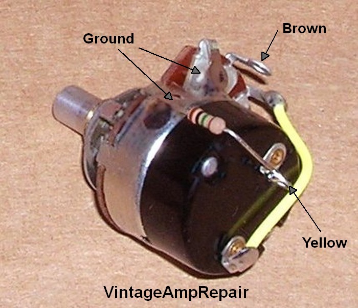
Photo by Randy Adkins, Vintage Amp Repair.
No one sells a 50KRA push-pull pot but you can make one by purchasing a common 250KA (non-reverse audio) push-pull pot and a 50KRA pot, then swap the 50KRA disc into the push-pull pot. I like to wire the push-pull switch pull-on but if you are a heavy tremolo user you can wire it pull-off .
Splice in a SPST ON/OFF mini switch in the Tremolo Intensity pot's input wire to completely disconnect the tremolo circuit.
To prevent the switch from popping when you engage tremolo you can place a 1M 1/4 watt resistor connected to ground (back of the pot) on one end and to the switch terminal that the amp's yellow wire connects to.
You can also reduce the tremolo circuit load and boost gain by replacing the stock 50K-RA (reverse audio) Tremolo Intensity pot with a 100K-RA pot.
Slow the Tremolo
This is a pretty common mod in amps with Fender style tremolo circuits. It allows a slower tremolo which I really like. The tremolo circuit has three disk capacitors. Two are .01uF and the other is .02uF. Replace the two .01uF caps with .02uF 400v (or higher voltage) to slow the tremolo. Many people like to use Orange Drop caps in the tremolo oscillator.
If after this mod you would like a faster maximum tremolo speed you can reduce the size of the 100k "Max Speed" resistor located on the Tremolo Speed pot.
This mod puts a little more strain on the tremolo tube so if the tremolo stops working after changing the two caps just install a fresh tube.
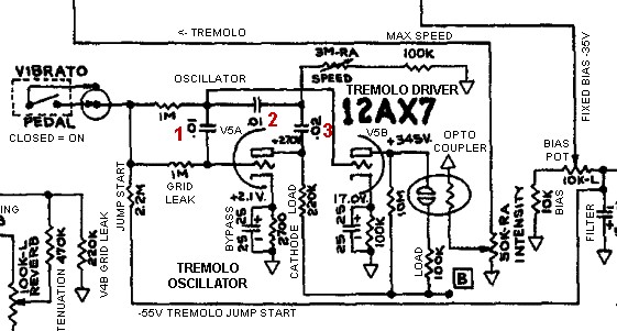
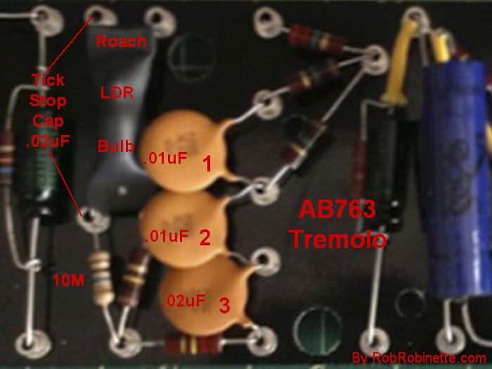
Disk cap numbers 1, 2 and 3 match the numbers in the schematic above. Replace #1 and #2 with .02uF 400v caps.
Stop Tremolo Ticking
The very strong tremolo oscillator signal can induce ticking into the amp's signal stream. First try to separate the tremolo driver plate (V5 pin 6) wire from any grid wires to stop the ticking. Pay close attention to the nearby V6A phase inverter grid (pin 2) wire.
Another option is to use a shielded cable like RG174 for the tremolo driver plate wire (V5 pin) to stop the transmission of the tremolo signal. This is almost a 100% fix for tremolo ticking. Ground the cable shield at only one end (either end) to prevent a ground loop.
If the above don't work then adding a .02uF cap to the tremolo roach should stop it.
Add a .02uF 400v (or higher voltage) cap across the left side of the tremolo roach to cure tremolo tick.
Tremolo Always On RCA Plug
Most amps with built-in tremolo have a female RCA jack for the tremolo foot switch. Tremolo is turned on when the footswitch is closed. This little shorted male RCA plug will turn on the tremolo without having to plug in the tremolo footswitch. I like to keep mine in all the time. The $1 Switchcraft 3501MX RCA plug is a perfect fit with a long center connector.
Switchcraft 3501MX RCA Plug
To short the plug insert a bare wire all the way through the connector--there's a hole in the end of the prong so run the wire all the way through then solder both ends of the wire to the plug. Be generous with the solder. Trim the wire flush at both ends and you're done.
Add Reverb Dwell Control
For amps with Fender style reverb circuits it's pretty easy to add a dwell control.
Simply replace the 12AT7 1M grid leak resistor with a 1MA pot.
12AT7 1M grid leak resistor clipped or removed. 1MA pot wired in its place.
The Reverb driver 1M grid leak works with the 500pF Reverb Filter cap to form a CR (capacitance-resistance) high pass filter with a corner freq of 318Hz (everything below 318Hz is cut). By replacing the 1M grid leak with a 1MA pot you will not only cut the amount of guitar signal entering the reverb driver as you turn down the Dwell pot but you will lower the CR corner freq as well which will allow more low freqs into the reverb circuit.
Place your dwell pot or trimmer wherever you want. Remove the 1M resistor. Wire the pot's left terminal to any ground. Wire the right terminal to the now empty right resistor eyelet (or turret). Wire the pot's center terminal (wiper) to V3 (12AT7) pin 7.
Darken the Reverb Tone
If your reverb tone is too bright you can add or adjust the bypass cap value shown in the above Reduce Reverb Noise & Oscillation mod. A .01uF (25v or higher) will audibly darken the reverb tone. You can play with that value to adjust the tone to your taste.
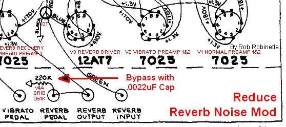
Solder a .01uF bypass cap around the 220k V4A Grid Leak resistor to darken the reverb tone.
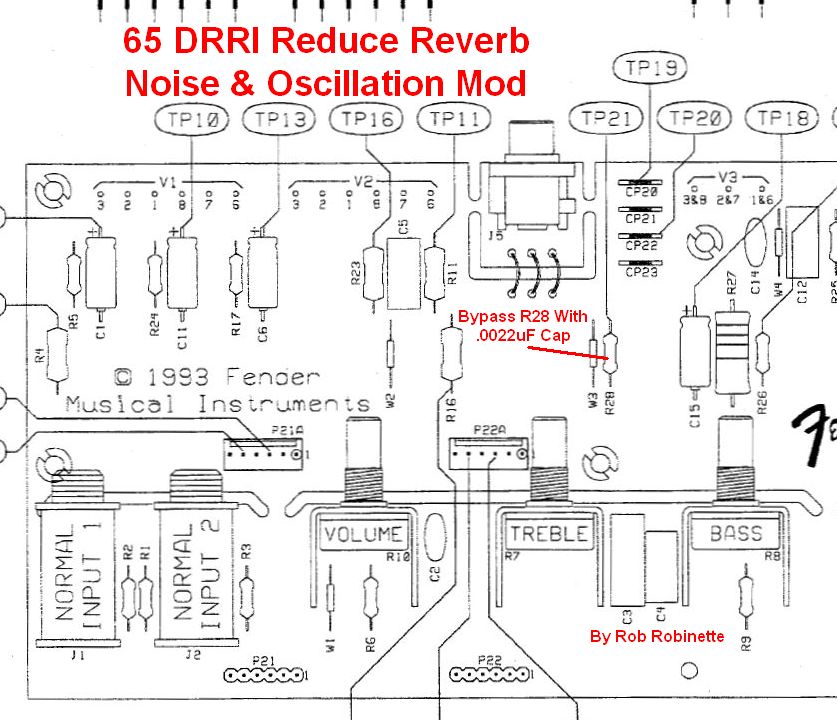
Resistor Bright Caps Mod
Putting 500pF bright caps around large value (220k to 470k) resistors in the preamp signal path will slightly brighten the tone of the modified channel. You can do one or both channels. You can alligator clip the cap in place temporarily to see if you like the mod.
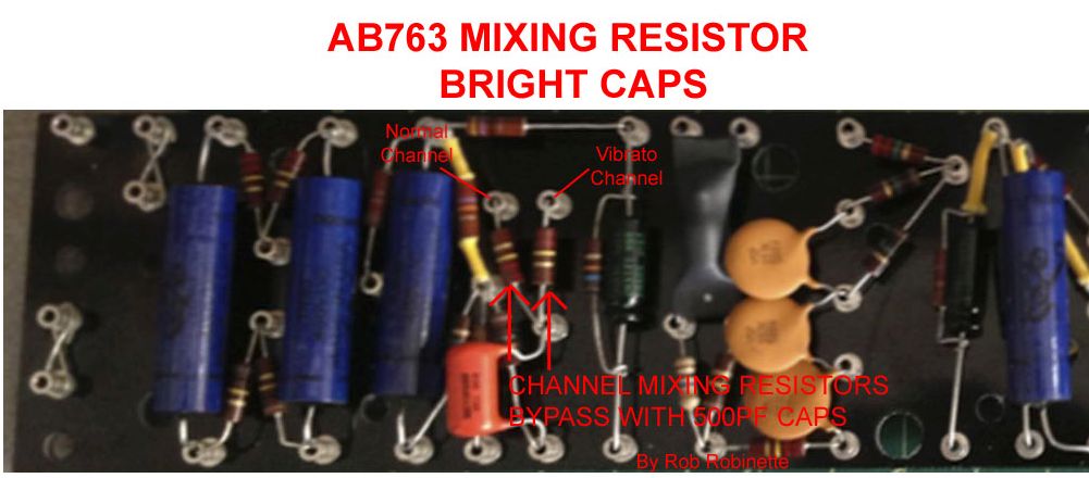
The 220k Channel Mixing resistor on the left is the Normal Channel's, the Vibrato Channel's resistor is on the right. Original photo by John Chabalko.
RobRob Reactive Power Brakes
We can use a $15 transformer and two $7 16 ohm 120 watt power resistors in parallel to create an inexpensive reactive dummy load capable of easily handling 100 watts to get your amp's high volume overdrive tone into a mixing board.
The power brake connects between your amp's speaker jack and mixing board and transforms all but a tiny bit of the amp's output to heat. Using this brake allows you to capture the complete tone of the amplifier including the compression and sustain generated in the output transformer. Of course it does not capture the speaker's effect on tone but as you can hear in the two video demos below that's not a problem.
The brake is reactive because a 1:1 transformer is used between the amp and the resistive load to create reactance to more closely mimic the reactive load of an actual speaker.
A Brake/Bypass switch allows you to bypass the brake and go direct to the speaker.
RobRob Reactive Power Brake In Action
Special thanks to Cos Man at CosLab4 for the Power Brake build and demo. These demos were recorded direct to his phone using his RobRob Reactive Power Brake. He's running the guitar into an HX stomp box, then to the tube amp, then to the RobRob Reactive Power Brake, then back to the HX stomp box with Ownhammer IR + reverb effects. The stomp box feeds his phone through USB (no mic used) for recording. He built the brake in a 30 caliber ammo box but it was a tight fit. He now recommends a larger 50 caliber ammo box be used. If you build the "Simplified" power brake (below, at the end of this section) it will fit into a 30 caliber ammo box.
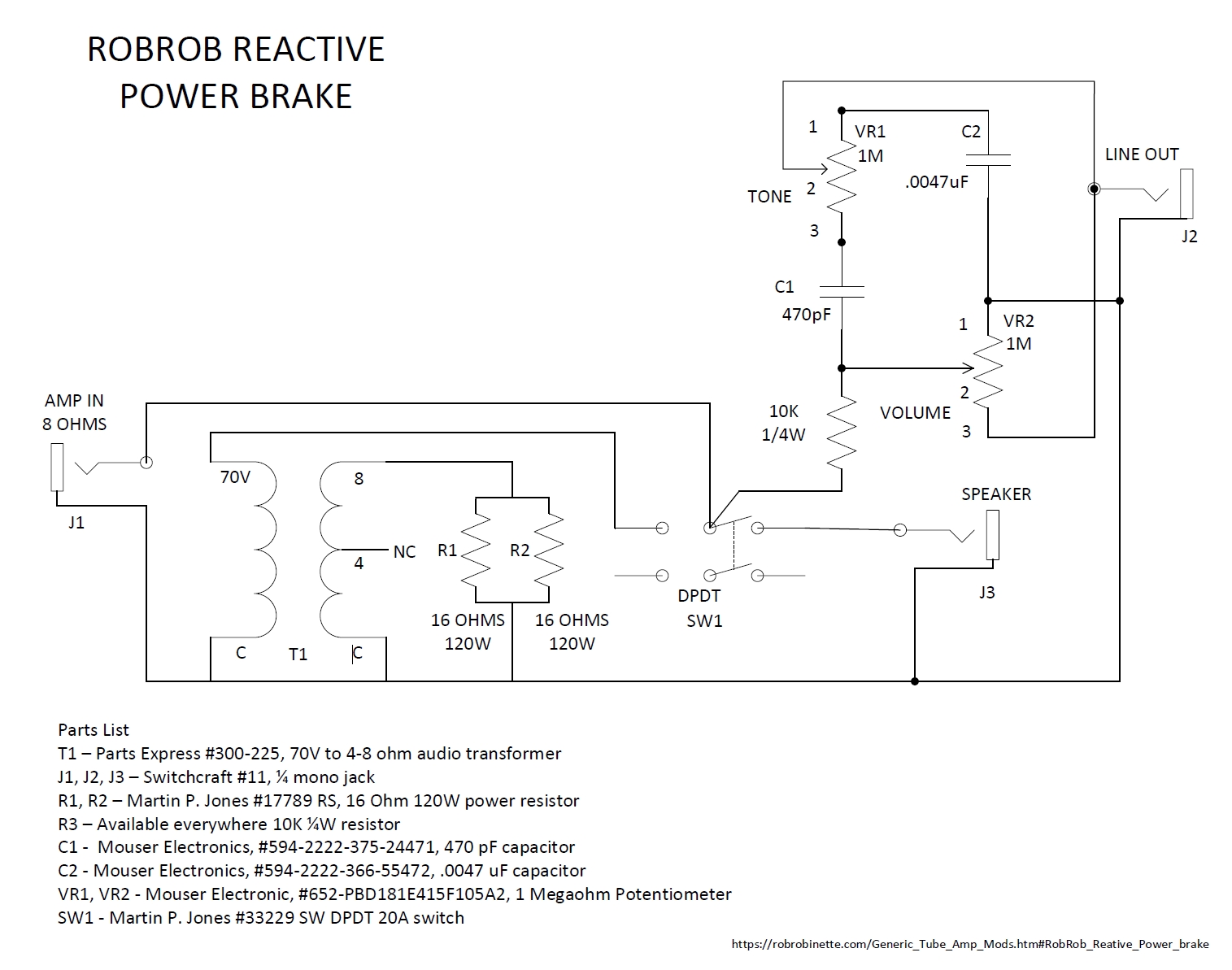
The Line Out at upper right is always active. Switch SW1 sends the amp output to either the speaker or the power brake. Note the parts list at bottom left.
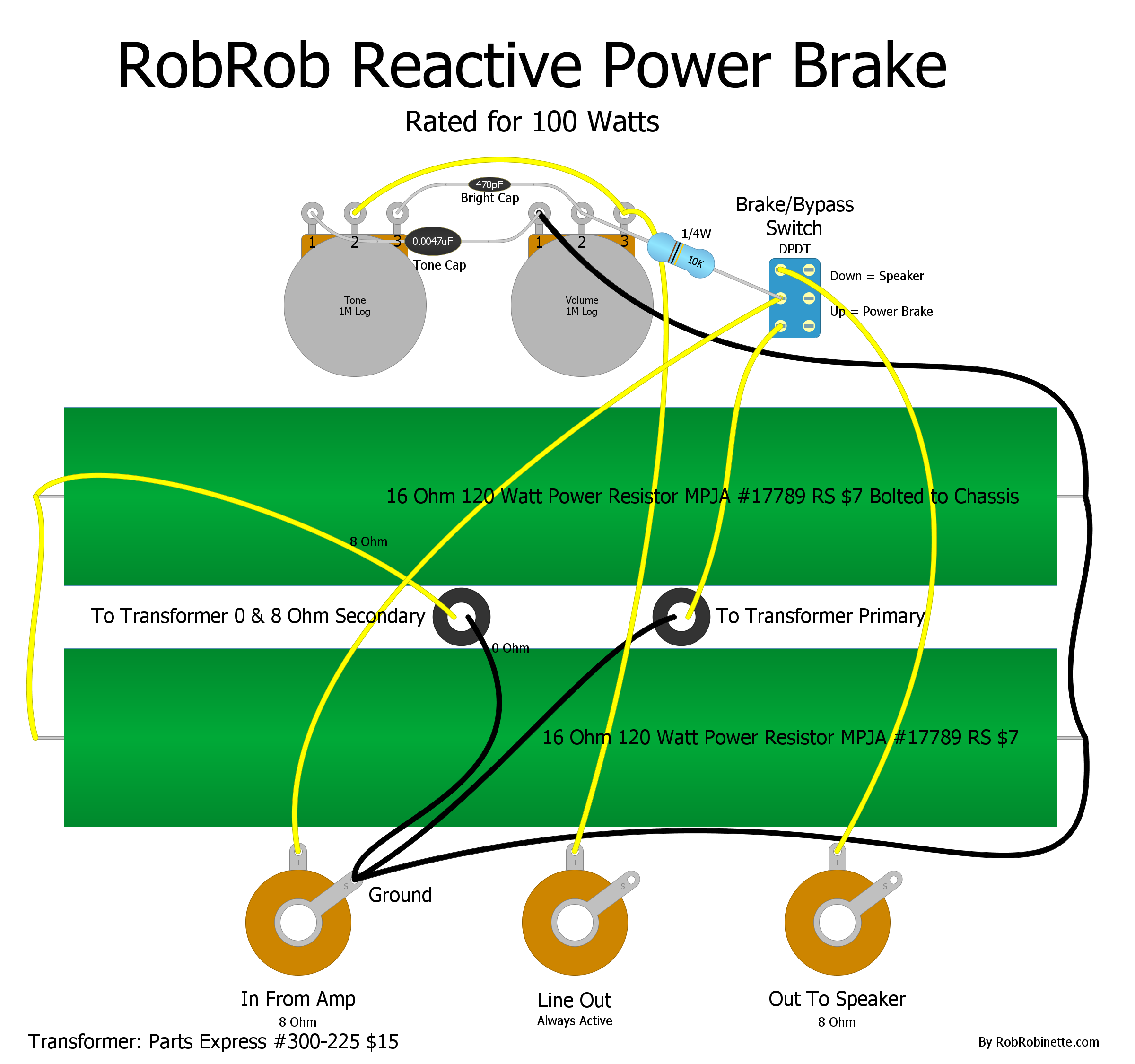
The amp's speaker out is connected to the "In From Amp" jack. The mixing board is connected to the always active "Line Out" jack. An optional speaker can be connected to the "Out To Speaker" jack. The Brake/Bypass Switch has two positions: Load or Bypass to the speaker. The transformer is mounted on top of the chassis and two holes with grommets are used to run its wires into the chassis. All three of the Switchcraft 11 jacks are grounded to the chassis. If you use insulated jacks then you must tie the ground terminals to the chassis.
For the transformer primary it does not matter how the wires (yellow signal and black ground) are connected to the two primary terminals.
For the transformer secondary the yellow signal wire is connected to the transformer 8 ohm secondary terminal, the 0 ohm terminal is connected to ground. The two big power resistors must be bolted to a metal chassis for heat dissipation. If they are not bolted to a metal chassis then the power brake's rating drops to about 30 watts.
The volume and tone pot circuit allow you to set the Line Out volume and tweak the tone.
You can build it for whatever speaker load you need:
For an 8 ohm load we use two 16 ohm 120 watt power resistors in parallel as shown above.
For a 2 ohm load we would use two 4 ohm 120 watt power resistors in parallel.
For a 4 ohm load we would use two 8 ohm 120 watt power resistors in parallel.
For a 16 ohm load we would use two 8 ohm 120 watt power resistors in series (connected end-to-end).
Note: No matter what load you use always connect the power resistors to the 8 ohm and 0 ohm transformer secondary terminals.
Parts Express #300-225 70V 100W High Power Speaker Line Matching Transformer
![]()
The input jack for the amp is connected to one of the two primary terminals on the left, the other primary terminal is grounded. Put the power resistors across the 8 and 0 terminals on the secondary (on the right above). Ground the 0 terminal. The 4 ohm terminal is not used.
16 Ohm 5% 120W Wirewound Power resistor: Steel Mtg. Bracket, Solder Terminals Use for Audio Loads, Power Supply test loads, etc. L: 8-3/4" O/A W: 1-1/4" O/A H: 2-1/2" O/A WT: .5
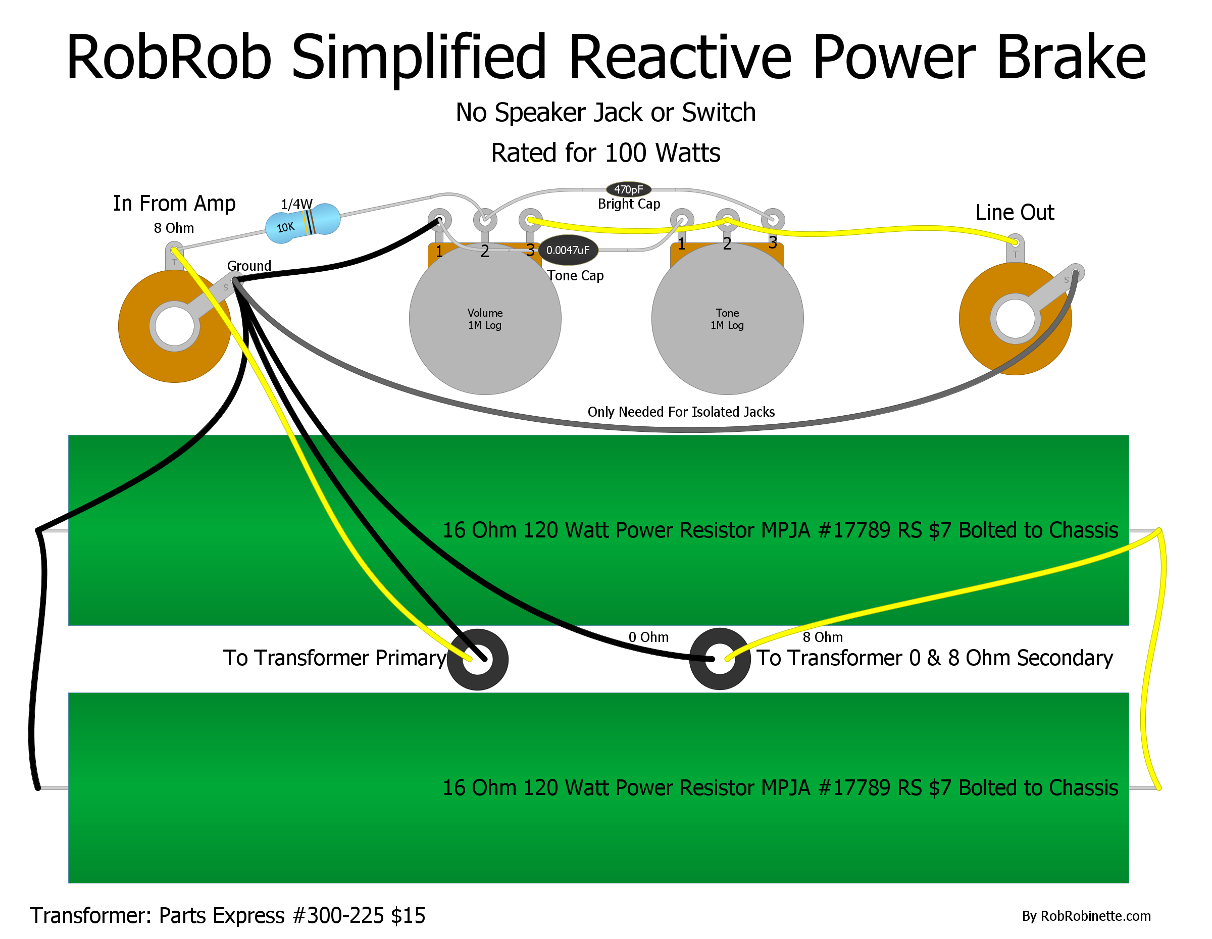
The speaker jack and switch have been eliminated for a simpler build.
Display Bias & Voltage Using Arduino
This schematic and Arduino code are by Thomas Rogan. He uses an Arduino to sample power tube cathode and plate voltage, compute bias and display the bias and voltages on a display attached to his amplifier.
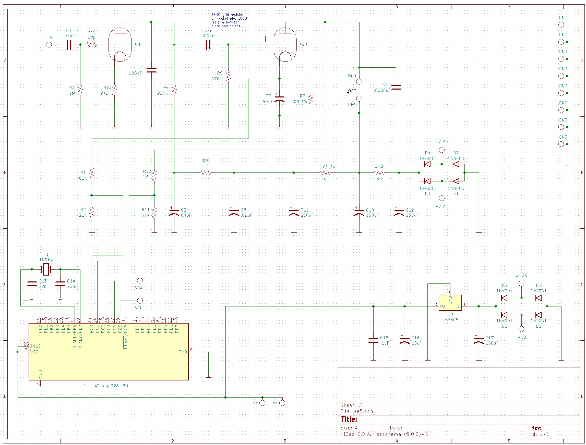
A 5v power supply powers the Arduino ATmega328 at lower left. Resistors R1 and R2 form a voltage divider to lower the power tube cathode voltage to a level the Arduino can use. Resistors R10 and R11 lower the power tube plate voltage.
Arduino Code
#include <Arduino.h>
/*
* By Thomas Rogan
* Note 1: Averaging of voltage measurements will help reduce jitter
* and improve readability on the display of your choice.
* Try averaging over 100 or 1000 readings and see what works
* best in your project.
*
* Note 2: Using measured voltages and resistances instead of nominal
* values will improve the accuracy of your output.
*/
//physical values - change these to match your measurements
double fiveVoltActual = 5.072; //the measured supply voltage to arduino chip
int cathodeResistorOhms = 387.2; //R7
double cathodeSensorOhms = 21770; //R2
double cathodeVoltageDividerOhms = 104870; //R1 + R2
double plateSensorOhms = 21830; //R11
double plateVoltageDividerOhms = 1017920; //R10 + R11
void setup(){
}
void loop() {
//take voltage measurements
double cathodeSensorVoltage = analogRead(A0) * (fiveVoltActual / 1023.0);
double plateSensorVoltage = analogRead(A1) * (fiveVoltActual / 1023.0);
//calculate current through R2
double cathodeSensorCurrent = cathodeSensorVoltage / cathodeSensorOhms;
//calculate voltage at cathode
double cathodeVoltage = cathodeSensorCurrent * cathodeVoltageDividerOhms;
//calculate current through R11
double plateSensorCurrent = plateSensorVoltage / plateSensorOhms;
//calculate plate voltage (minus cathode voltage)
double plateVoltage = (plateSensorCurrent * plateVoltageDividerOhms) - cathodeVoltage;
//calculate current through cathode resistor R7
double cathodeCurrent = cathodeVoltage / cathodeResistorOhms;
//calculate plate dissipation
double plateDissipationPower = plateVoltage * cathodeCurrent;
//Insert your display code here
}
By Rob Robinette
References
RCA Corporation, RCA Receiving Tube Manual, RC30.
Merlin Blencowe, Designing Tube Preamps for Guitar and Bass, 2nd Edition.
Merlin Blencowe, Designing High-Fidelity Tube Preamps
Morgan Jones, Valve Amplifiers, 4th Edition.
Richard Kuehnel, Circuit Analysis of a Legendary Tube Amplifier: The Fender Bassman 5F6-A, 3rd Edition.
Richard Kuehnel, Vacuum Tube Circuit Design: Guitar Amplifier Preamps, 2nd Edition.
Richard Kuehnel, Vacuum Tube Circuit Design: Guitar Amplifier Power Amps
Robert C. Megantz, Design and Construction of Tube Guitar Amplifiers
Neumann & Irving, Guitar Amplifier Overdrive, A Visual Tour It's fairly technical but it's the only book written specifically about guitar amplifier overdrive. It includes many graphs to help make the material easier to understand.
T.E. Rutt, Vacuum Tube Triode Nonlinearity as Part of The Electric Guitar Sound
[ How the 5E3 Deluxe Works ] [ Deluxe Models ] [ DRRI & 68 CDR Mods ] [ Amp Troubleshooting ] [ My 5E3 Build ] [ Spice Analysis ] [ The Trainwreck Pages ] [ Fender Input Jacks ] [ B9A Prototype Boards ]