How The TMB Tone Stack Works
By Rob Robinette
The FMV or TMB (Fender/Marshall/Vox Treble Mid Bass) tone stack has been around since the 1950's and has become a staple with Fender and Marshall amps. When Marshall copied the Fender 5F6-A Bassman almost verbatim to create the JTM45 amplifier the Fender TMB tone stack came with it and it's still being designed into new amps today.
The 5F6-A Bassman and AB763 Blackface TMB Tone Stack
On this page I use the 5F6-A Bassman's tone stack but all the stack's component values can vary in other amps. To see how component values affect the tone stack's output you can use the Duncan Amps Tone Stack Calculator program discussed below.
The TMB tone stack is passive, meaning it can only remove frequencies, not boost them. The TMB stack is made up of several low and high pass audio filters that work together to work their magic. It's a relatively low impedance circuit (high load) so it works best when fed by a low impedance source such as a cathode follower like in the 5F6-A, JTM45 and many other amplifiers but it still works well when fed by a tube plate such as done in the AB763 blackface amps.
Part of what makes a Fender amp a Fender amp is the phase shift created in the Fender tone stack. When an audio signal flows through a capacitor there is a slight delay as the cap fills and drains. This delay is called "phase shift." The 5F6-A Bassman, blackface and silverface amps use a large .1uF bass cap that induces quite a bit of phase delay compared to the very small 250pF treble cap so lower frequencies are phase shifted more than high frequencies. The treble pot blends the treble and bass signals with their phase differences which generates harmonic and intermodulation distortion and creates the "Fender Shimmer". It's kind of like having two guitars, one playing mid and high frequencies and one playing mid and low frequencies but they are slightly off on their timing. It is also similar to having a built-in chorus pedal for mid frequencies. Maximum shimmer occurs around an equal treble and bass volume mix so think of the treble control as also being the "shimmer control". Play with it to create the famous Fender shimmering clean tone.
The seemingly simple TMB tone circuit is surprisingly complex due to the interactive nature of its four audio filters and phase shift distortion. I will attempt to describe how it works in the most simple way possible. We'll start with an overview of the tone stack then examine the Treble, Bass and Mid filters separately in detail.
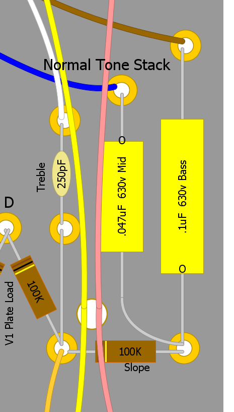
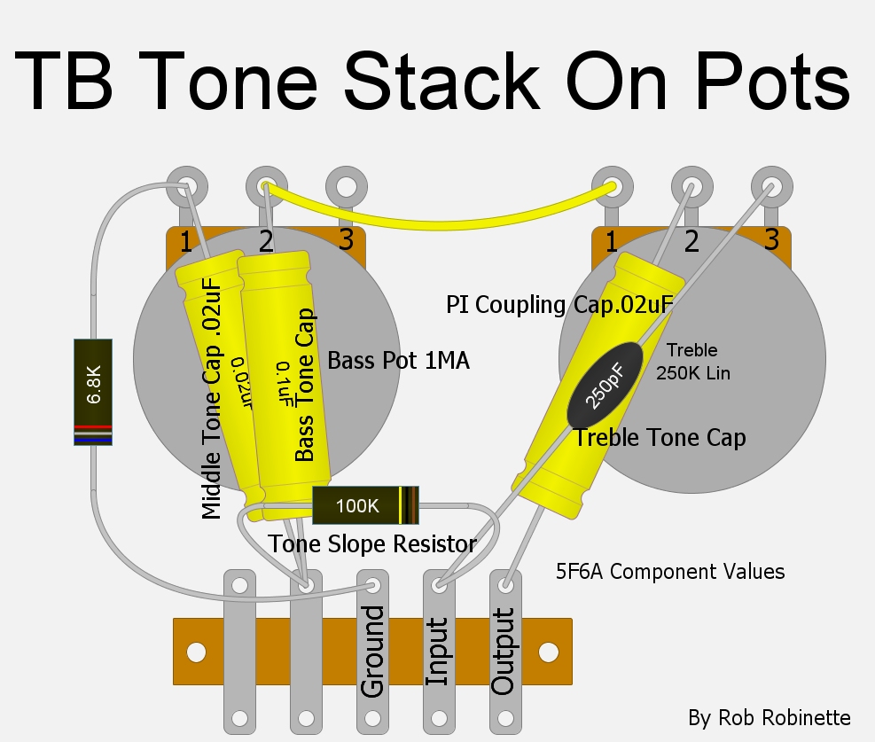
The Fender 5F6-A Bassman Tone Stack

Guitar AC signal voltage enters the tone stack at upper left and flows through all three tone caps. Note the Bass Pot is wired as a variable resistor while the Treble and Mid Pots are wired as potentiometers. In typical amp circuits all three tone caps also function as coupling caps to prevent high voltage DC from flowing downstream.
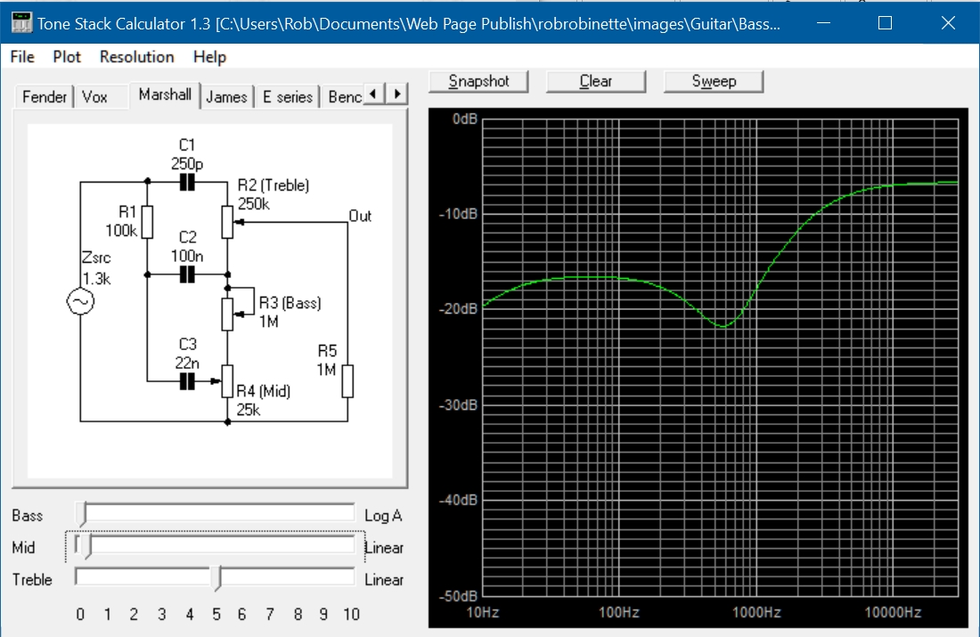
Duncan Tone Stack Calculator Graph of 5F6-A Tone Stack
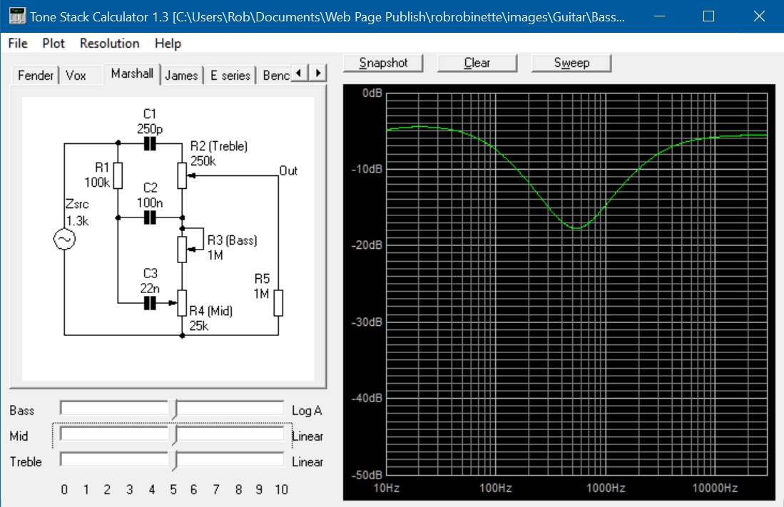
All three tone controls are set to their mid point. Note the mid scoop (dip in graph) at 500Hz. Fender used the mid scoop to compensate for typical guitar pickups which over emphasize mid frequencies.
The free Duncan Tone Stack Calculator program is a free, very cool and easy to use Windows program that will help you understand how interactive the tone controls really are. Not only can you move the tone pot sliders and see how the frequency response graph changes but you can also double-click any component in the schematic and change its value. For example you can double-click on the tone slope resistor and see what changing its value does to the slope of the frequency response graph. Resistor R5 is not part of the tone stack, it represents the downstream load. We use an output load of 1M (R5 at far right of the Duncan schematic above) to simulate the next gain stage 1M grid leak resistor. For the 5F6-A Bassman, which feeds the tone stack with a cathode follower, we use a Zsrc (source impedance shown at far left on schematic) of 1.3k. If you want to simulate a tone stack fed by a normal gain stage plate, such as in the AB763 blackface, then use a Zsrc from of 38k.
Table of Contents
Mid Pot Wired as Variable Resistor
Point-to-Point Baxandall or James Tone Stack
Audio Filters
Quick Audio Filter Review
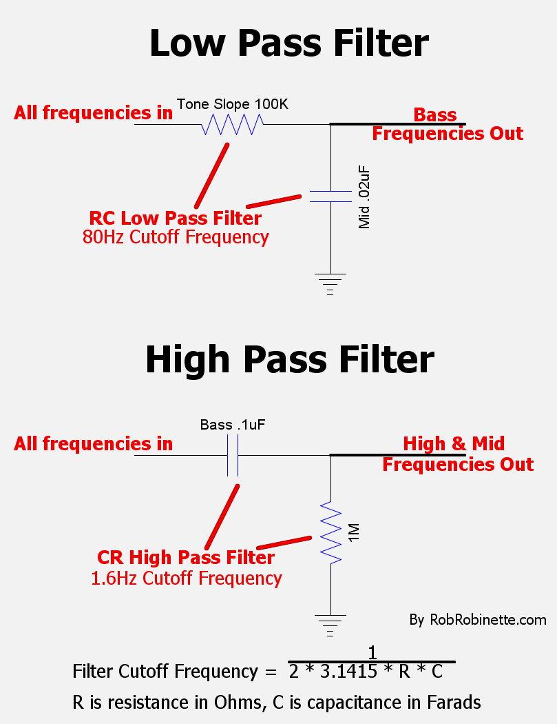
An RC (resistance-capacitance) low pass filter has a resistor first followed by a capacitor connected to ground. A low pass filter allows low frequencies to pass but high frequencies are blocked. The TMB tone stack has only one low pass filter. A CR (capacitance-resistance) high pass filter has the capacitor first followed by a resistor connected to ground. A high pass filter allows high frequencies to pass but blocks low frequencies. The TMB tone stack has three high pass filters.
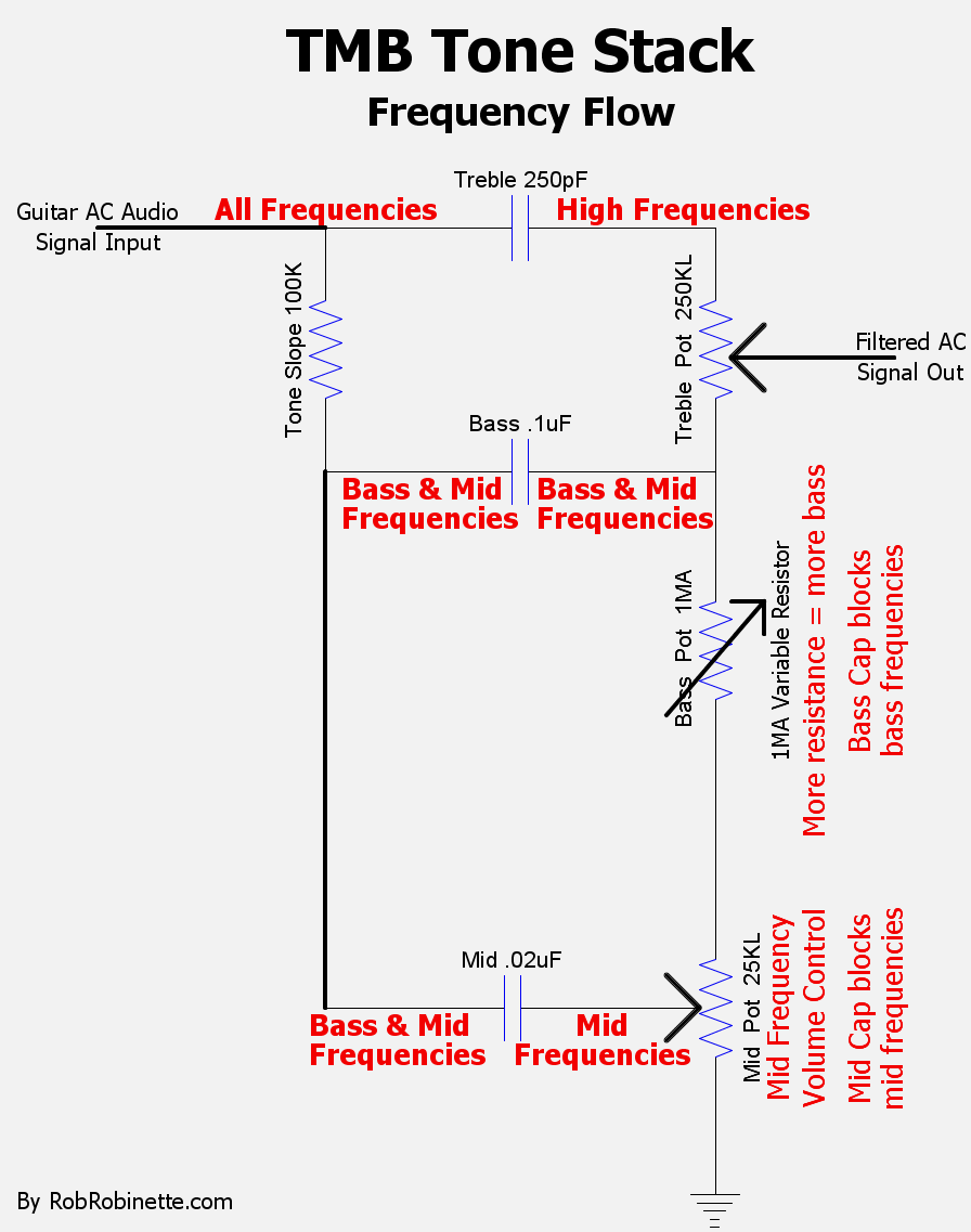
Tone Stack Overview
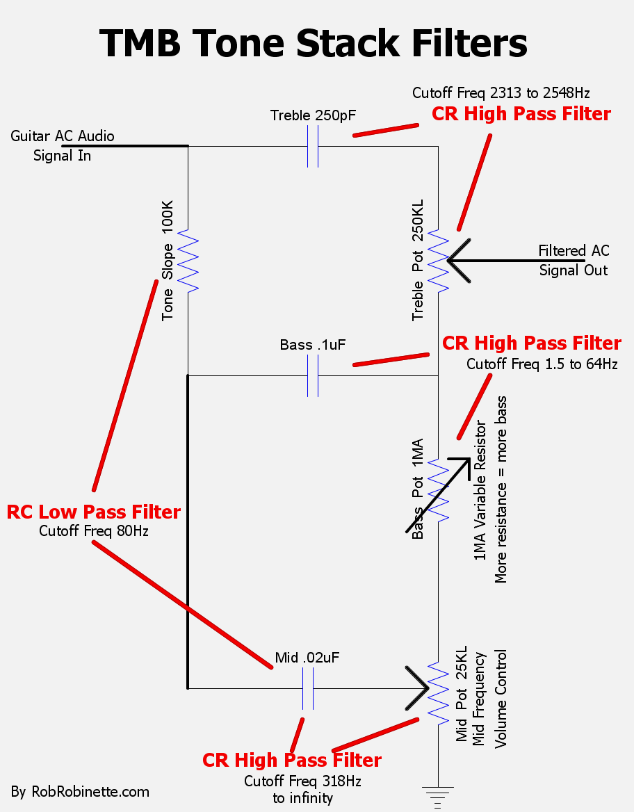
One low pass and three high pass filters make up the tone stack. Note how the bottom high pass filter formed by the Mid Cap + Mid Pot varies from 318Hz (Mid Pot at max) all the way up to infinity (Mid Pot at min). With an infinitely high cutoff frequency no audio frequencies will pass--they will all be blocked. Note the Tone Slope Resistor does not form a low pass filter with the Bass Cap because they are connected in series. The Tone Slope Resistor + Mid Cap form the only low pass filter.
The guitar audio signal enters at upper left and encounters the Treble cap and Tone Slope resistor. The Tone Slope Resistor works as a frequency divider with high frequencies passing around it to the Treble Cap and low and mid frequencies passing through it to the Bass and Mid Caps. A larger value Tone Stack resistor will pass fewer bass and mid frequencies so its value changes the balance or "slope" of the tone stack's frequency response.
The treble high pass filter made up of the Treble Cap + Treble Pot blocks frequencies below approximately 2400Hz and allow higher frequencies to pass. The high frequencies are sent to the top terminal of the Treble Pot. The bass and mid frequencies that pass through the bass and mid filters flow to the Treble Pot's lower terminal so the Treble Pot is a balance control that allows you to select between the high and low frequencies at its outside terminals.
The Tone Slope Resistor + Mid Cap low pass filter works with the bass and mid high pass filters formed by the Bass Cap + Bass Pot and the Mid Cap + Mid Pot to form band pass filters. Band pass filters remove frequencies above and below the desired band of frequencies. The bass and mid band pass filters are made up of a low pass filter that removes high frequencies and a high pass filter that removes bass & mid frequencies to leave a band of frequencies that pass through the tone stack.
The Tone Slope + Mid Cap low pass filter's cutoff frequency is a very low 80Hz so how do any mid frequencies pass on to the Treble Pot? The Mid Pot's resistance (below the wiper) comes after the low pass filter, which reduces the low pass filter's effectiveness so some mid & high frequencies pass through the filter and on to the Treble Pot.
The bass control's high pass filter cutoff frequency varies between 1.6Hz and 64Hz. With the Bass Pot full up the bass high pass filter only blocks frequencies below 1.6Hz so all guitar and bass frequencies get through. With the Bass Pot full down the filter blocks frequencies below 64Hz so low bass is filtered out.
The mid control's high pass filter cutoff frequency varies between 318Hz to infinitely high. With the Mid Pot full up the mid high pass filter only blocks frequencies below 318Hz. With the Mid Pot full down the mid filter blocks all frequencies.
The TMB tone stack will interact with a high impedance driving stage such as the plate of a 12AX7 as in Fender blackface amps. The TMB stack's high load (low impedance) loads down the guitar signal coming off the tube plate causing attenuation. In other words the TMB stack's low impedance is in parallel with the driving tube's plate load resistor which lowers gain.
The Treble Pot has high frequencies at its upper terminal and mid and low frequencies on the lower terminal. Turning the Treble Pot changes the balance between the two frequency groups.
The Treble Control
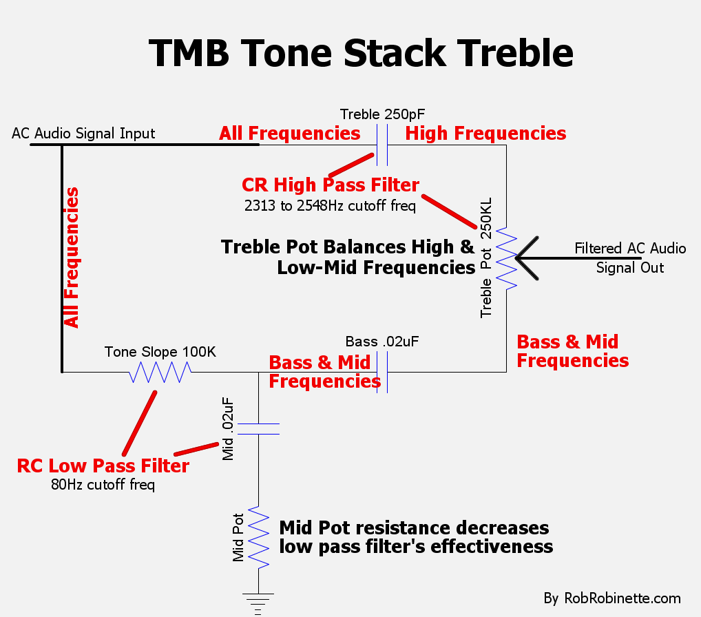
Treble Cap + (Treble Pot resistance of 250k + Mid Pot resistance) = high pass filter, so high frequencies flow across the top of the tone stack. Tone Slope Resistor + Mid Cap = low pass filter, so bass and mid frequencies flow through the Tone Slope Resistor and Bass Cap around to the Treble Pot.
The Treble Cap + Treble Pot high pass filter blocks frequencies below 2313Hz (with the Mid Pot at max) to 2548Hz (with the Mid Pot at minimum).
Turning the Treble Pot does not change the Treble Cap + Treble Pot high pass filter cutoff frequency because the Treble Pot's full 250k of resistance is always in the filter's path to ground--moving the Treble Pot's wiper does not change this. Turning the Treble Pot adjusts the balance between high frequencies on the top side of the Treble Pot and Bass & Mid frequencies on the bottom side of the pot.
As mentioned above, the tone stack's low pass filter cutoff frequency is a very low 80Hz but the Mid Pot's resistance below the wiper comes after the low pass filter, which reduces the low pass filter's effectiveness so some mid and high frequencies pass through the filter to the Treble Pot.
The Mid Pot's resistance below its wiper is added to the treble high pass filter's resistance. The treble high pass filter's resistance ranges from 250k with the Mid Pot set to minimum which gives a cutoff frequency of 2548Hz, to 275k ohms with the Mid Pot at Max and a cutoff frequency of 2313Hz.
The Bass Pot setting has no effect on the treble high pass filter cutoff frequency because the treble filter's path to ground can flow through the Bass and Mid Caps to flow around the Bass Pot.
The Tone Slope Resistor got its name because its resistance affects the balance between high frequencies that flow across the top of the tone stack and bass & mid frequencies that flow below through the rest of the tone stack. A smaller Tone Slope Resistor will tilt the frequency balance toward bass frequencies by reducing treble and increasing bass. A larger resistor will tilt it toward high freqs and less bass. A larger Tone Slope Resistor will also reduce the Tone Stack's load (raise its impedance). That's one of the reasons the Fender blackface amps use a 100k Tone Slope resistor.
The Bass Control
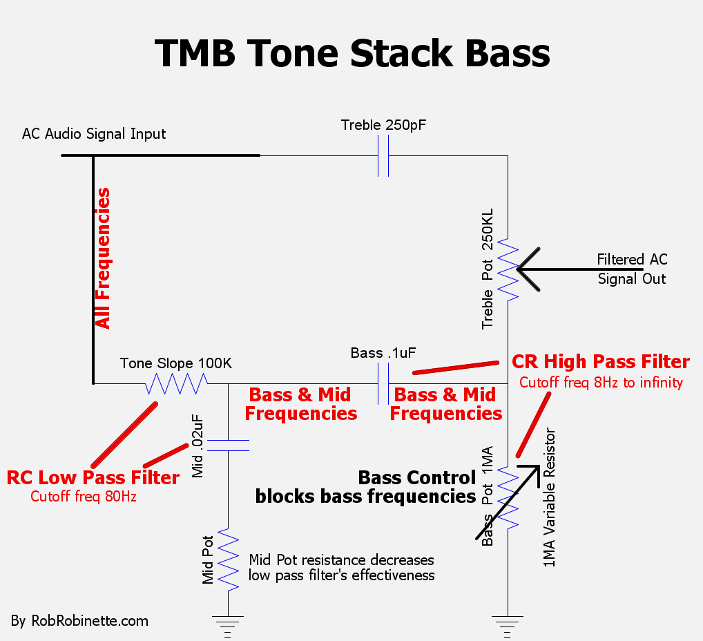
Slope Resistor + Mid Cap = low pass filter, so bass and mid frequencies flow on to the Bass Cap. Bass Cap + (Bass Pot + Mid Pot 25K resistance) = high pass filter, so the Bass Pot blocks low frequencies.
By filtering the guitar audio through a low pass filter followed by a high pass filter (Bass control) a variable band pass filter is created that only affects bass frequencies.
With the bass high pass filter's resistance of 1M Bass Pot + Mid Pot 25K = 1.025M with the Bass Pot at max gives a cutoff frequency of 1.6Hz.
With the bass high pass filter's resistance of 0 Bass Pot + Mid Pot 25K = 25K with the Bass Pot at minimum gives a cutoff frequency of 64Hz.
As mentioned above, the tone stack's low pass filter cutoff frequency is a very low 80Hz but the Mid Pot's resistance below the wiper comes after the low pass filter, which reduces the low pass filter's effectiveness so some mid and high frequencies pass through the filter to the Bass Cap.
The Bass Pot has no effect when the Mid and Treble Pots are full down.
The Mid Control
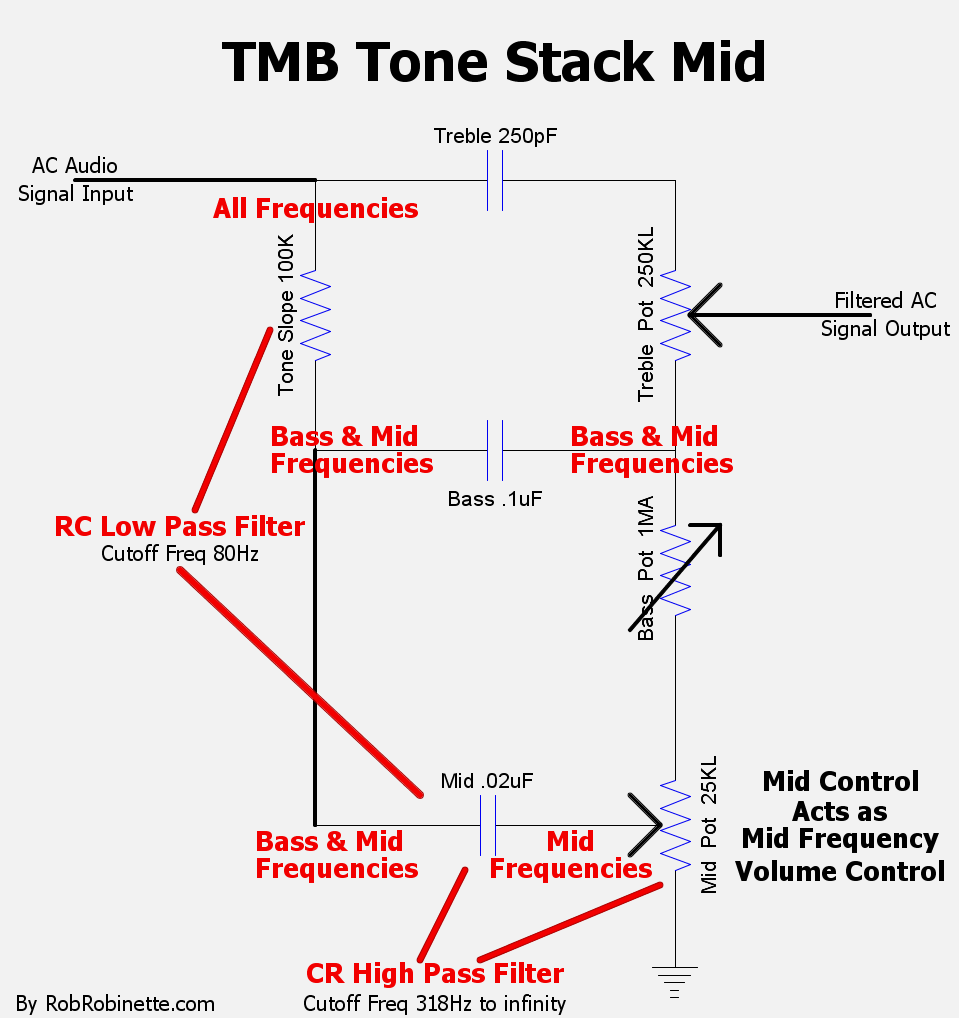
The Tone Slope Resistor + Mid Cap low pass filter passes bass and mid frequencies to the Mid Cap. The Mid Cap + Mid Pot resistance = high pass filter. The combination of the low pass and high pass filters creates a band pass filter so only mid freqs make it through.
The Mid Pot is a band pass filter that functions like a mid frequency volume control. At higher Mid Pot settings the control acts as a simple high pass filter which blocks low freqs but allows mid freqs through. As you turn down the Mid Pot, the mid filter's cutoff frequency increases. The cutoff frequency runs from 64Hz with the Mid Pot at max to infinitely high with the Mid Pot full down.
A high pass filter with an infinitely high cutoff frequency blocks all frequencies so no audio will pass.
As mentioned previously, the tone stack's low pass filter cutoff frequency is a very low 80Hz but the Mid Pot's resistance below the wiper comes after the low pass filter, which reduces the low pass filter's effectiveness so some mid and high frequencies pass through the filter. But dial the Mid Pot full down and the Tone Slope + Mid Cap's low pass filter really does cut off all frequencies above 142Hz so only low bass frequencies make it to the lower side of the Treble Pot.
In some amps the Mid Pot is replaced by a simple resistor with a typical value of 6.8k. In the AB763 blackface amps Fender used either a 6.8k resistor or a 10KA (audio or log) Mid Pot wired as a variable resistor (with input and wiper terminals jumpered). A quirk of wiring the Mid Pot as a variable resistor causes a complete dropout of the guitar signal when all three tone controls are turned full down.
All of the tone stack filters use the Mid Pot ground connection as their ground so if you disconnect the Mid Pot's ground then impedance goes to infinity, all filtering of the tone stack stops and the tone stack load disappears which gives a large jump in gain. This is how a "Raw Switch or Tone Cut" works. It breaks the tone stack's ground connection so all, unfiltered guitar audio flows out the Treble Pot wiper. The Raw Switch can also be replaced by a 100KA pot wired as a variable resistor for a "Raw Control" for a variable tone stack cut--more Raw Pot resistance = less tone stack, higher impedance, less load and less signal loss. Less Raw Pot resistance = more filtering, lower impedance, more load and more signal loss. My preferred option is to change the Mid Pot to a 100KA (audio taper) pot which will function as a Mid/Raw Pot. At higher settings all filtering is reduced for less load, less signal loss, more gain and a more "tweed-like" flat frequency response.
Tone Stack Phase Shift & Fender Shimmer
The following by Tim Breeden is a very good overview of how the Fender tone stack and its large .1uF bass cap cause frequency dependent phase shift which causes "the Fender Shimmer." When an AC audio signal enters a capacitor there is a slight delay as the cap fills and drains. This delay is called "phase shift". The larger the cap value the more delay so in the tone stack bass frequencies are phase shifted more than treble frequencies. Fender Shimmer is caused by this differing phase shift between treble (goes through a tiny 250pF treble cap) and bass (goes through large .1uF cap). The shimmer occurs where the treble and bass frequencies overlap--the mid highs to mid lows. The treble control acts as a mixer for the treble and bass and maximum shimmer will occur near the treble control mid point when bass and treble are most balanced. The effect is similar to two guitars playing, one playing treble and one playing bass and they are slightly out of time which creates a nice, fat mid frequency tone. As guitar notes decay their harmonic overtones cause varying amounts of phase shift which causes the actual wavering "shimmer" effect.
By Tim Breeden
I read a lot of articles about tone stacks that are centered around the frequency response of the circuit and how to trick it out. Unfortunately, it is one of the most misunderstood circuits out there and these articles only deal with half of the story. Almost any other tone circuit out there can outperform the tone stack in terms of quality of signal and band control. The Fender Tone Stack is unique because of the special effect it creates, the Fender Shimmer. And it does this through specialized, intentional, phase distortion.
The Fender tone stack revolutionized the tone of electric guitars. Leo had been experimenting with various tone controls throughout the 1950s. When he came across the tone stack circuit, he found the magic spark that created the Fender shimmer and everybody copied him. The shimmer is a blending of tones from the treble control, creating the effect of two guitars playing, one up high and one down low, through the midrange. When the note decays, it interpolates the harmonics from the two signals with additions and subtractions of phase interaction: the shimmer. It only occurs where the bass and treble capacitor frequency response overlaps at equal volumes.
The tone stack capacitors and slope resistor control the characteristics of the shimmer, its center point, maximum width and bandwidth as well as normal tone functions. A .02uF bass cap such as the one found in the Fender Blues Junior will not have as much shimmer as the Fender blackface AB763 standard .1uF, as it doesn't have as much phase delay. A change in the slope resistor will change the amount of bass but also shift the Shimmer to a different center point almost a full octave higher. It may also narrow the frequency overlap and reduce shimmer intensity.
The tone stack calculators found online do not account for or describe phase interactions yet it is the most important feature of that circuit. Most other tone circuits try to minimize phase shift and interaction but the Fender tone stack shimmer celebrates it. Take a closer look at your mods to ensure you don't chase it away.
The greater the difference in capacitance between the treble and bass caps, the greater the shimmer. The 5F6-A tweed Bassman and Blackface AB763 tone stacks with their large .1uF bass caps, tiny 250pF treble caps and 100k tone slope resistors seem to work best at maximizing the shimmer effect. A lower 56k tone slope resistor raises the point of maximum shimmer a full octave. AB763 tone stack Fender Shimmer is one of the main reasons blackface amps are considered the high water mark of Fender amps. The shimmer added the missing ingredient needed to make the then new solid body electric guitar sound its best.
Note: The original 5F6-A tweed Bassman schematic and layout show a small .02uF bass cap and 56k tone slope resistor. Every real tweed Bassman I have seen actually came with a .1uF bass cap and 100k tone slope resistor--just like the blackface AB763. Even Fender's modern Bassman reissues have these tone stack values. This implies that Leo Fender discovered the Fender Shimmer during the development of the Bassman and changed its tone stack after the schematic and layout were created. He may have intentionally left the incorrect component values in the amp documentation to prevent someone (Marshall) from stealing the shimmer. When Marshall copied the 5F6-A Bassman to create the JTM-45 he did in fact copy the schematic's small .02uF bass cap value (suckah!). He also changed the tone slope resistor to a very low 33k. The lower bass cap and tone slope values reduce shimmer and move it almost two octaves higher in frequency than the AB763 tone stack.
Mid Pot Wired as Potentiometer or Variable Resistor?
The TMB tone stack's Mid Pot can be wired as a potentiometer as in the 5F6-A Bassman or as a variable resistor (with input and wiper terminals jumpered together) as they are in the Fender AB763 blackface amps. The difference is subtle but wiring the Mid Pot as a potentiometer shows the treble and bass high pass filters a resistance to ground that does not vary as you adjust the Mid Pot so there is less interaction between the tone controls.
With the Mid Pot wired as a variable resistor treble frequencies drop off more when the mid control is turned down. When the Bass Pot is turned down the mid control will also cut bass frequencies as it is turned down. With the Mid Pot wired as a variable resistor a complete dropout of the guitar signal occurs when all three tone controls are turned full down.
Mid Control Wired as Potentiometer
Bass and Mid pots set to minimum. Note the Mid Pot, R4 at bottom center of the schematic wired as a potentiometer.
Mid Control Wired as Variable Resistor
With the Mid and Bass Pots both full down high frequencies are 4dB lower and bass frequencies are severely cut.
Annotated 5F6-A Schematic With Signal Flow and Component Function
Note the TMB Tone Stack at the center of the schematic. Guitar signal path shown in yellow. What do all those parts do? Click on the graphic to see the full size and readable schematic. Note: Production 5F6-A Bassman amps left the factory with a 100k tone slope resistor and .1uF bass cap even though the schematic and layout show 56k and .02uF.
Point-to-Point TMB Tone Stack
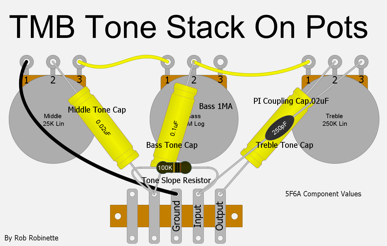
Four terminal strip terminals to support the components. A Raw control or switch would be inserted between the Middle pot and the ground terminal.
The Middle pot has been replaced with a 6.8K resistor.
Point-to-Point Baxandall or James TB Tone Stack
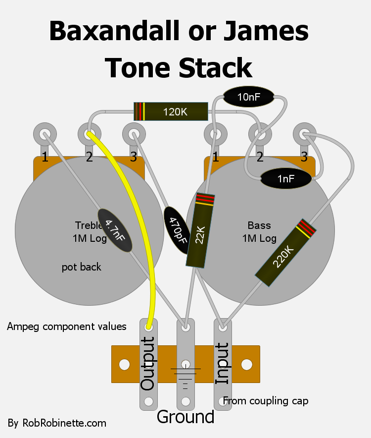
The James (or passive Baxandall) Treble/Bass tone stack allows more control with less quirks than the Fender/Marshall/Vox TMB tone stack. Unlike the Fender tone stack you can achieve a mid hump by setting the treble and bass controls low. The Baxandall does not generate the TMB "Fender Shimmer" effect. More info on the Baxandall circuit here.
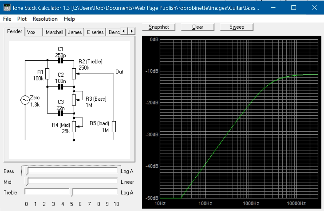
Duncan Tone Stack Calculator Graph of Baxandall
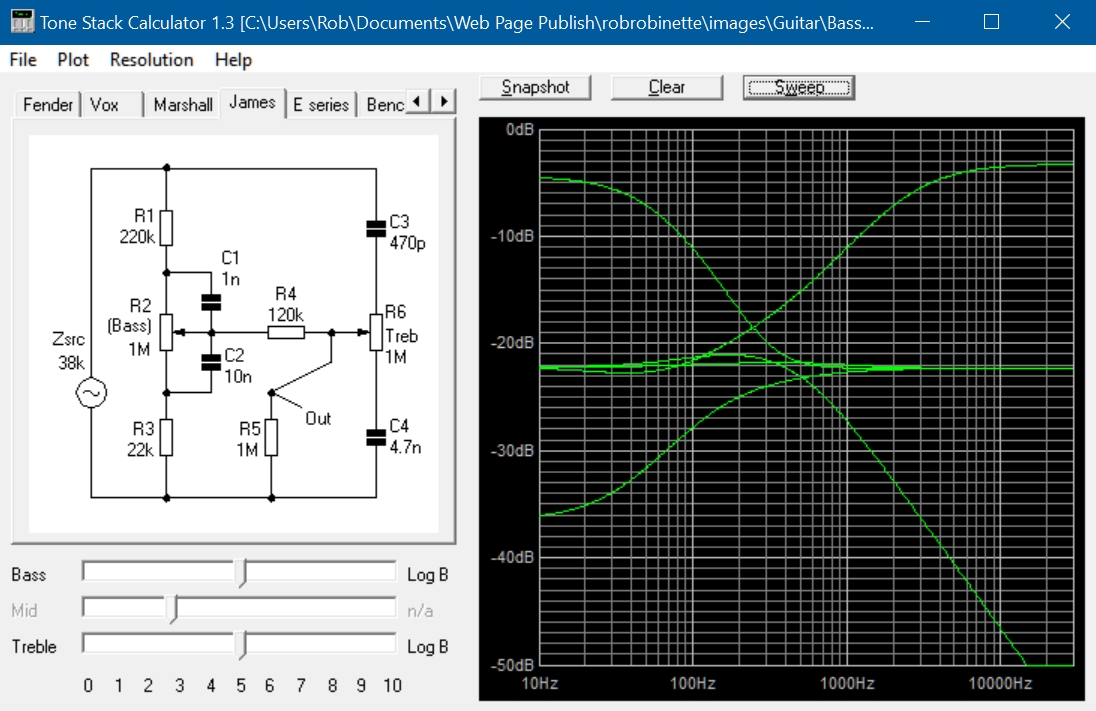
Flat frequency response with no mid scoop with bass and treble set to 5. Turn up the bass and treble for a traditional "mid scoop," turn down the bass and treble for a "mid hump." Tone stack input is at Zsrc (source impedance) on the left of the schematic, output is at "Out" at lower-center-right. Guitar open E string is 82Hz, two lines to the left of 100Hz on the bottom of the graph. Resistor R5 is not part of the tone stack, it represents the downstream load.
The passive Baxandall or James tone stack acts very differently than the Fender TMB tone stack. With the treble and bass controls set to mid resistance you get an almost perfectly flat frequency response. You can even get a "mid hump" emphasizing mid frequencies that is impossible with the Fender tone stack. The two tone controls have almost no interaction with one another which is another big difference from the Fender tone stack.
The Baxandall tone stack cannot act as a coupling cap as the Fender tone stack does so you must put a coupling cap between a tube plate and the Baxandall input to keep high voltage out of the tone pots. You can feed this tone stack from a tube plate (38k typical impedance) or a cathode follower (1.3k typical) with little effect on the circuit. I do not recommend replacing a Fender/Marshall/Vox tone stack with a James/Baxandall tone stack because it does not generate "Fender Shimmer." The component values shown on this page are from an Ampeg guitar amp with a center frequency around 400Hz. The Baxandall is an excellent tone control for stereo audio amps but different component values are needed to move the center frequency up to 1,000Hz.
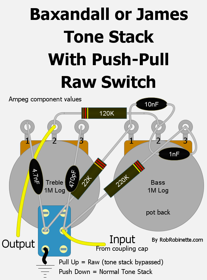
A Raw control or switch can be inserted to effectively remove the tone circuit from the amp. When you remove the circuit's ground all the tone shaping and circuit load disappear and you get a flat frequency response and huge 22dB jump in output. If you want to reduce the volume jump from normal to raw you can place a resistor between the bottom left and mid left switch terminals. A resistor value between 2.7k (small volume change when switching) to 1M (big volume change) can be used. You can also use any DPDT switch for the raw switch.
By Rob Robinette
References
RCA Corporation, RCA Receiving Tube Manual, RC30.
Merlin Blencowe, Designing Tube Preamps for Guitar and Bass, 2nd Edition.
Merlin Blencowe, Designing High-Fidelity Tube Preamps
Morgan Jones, Valve Amplifiers, 4th Edition.
Richard Kuehnel, Circuit Analysis of a Legendary Tube Amplifier: The Fender Bassman 5F6-A, 3rd Edition.
Richard Kuehnel, Vacuum Tube Circuit Design: Guitar Amplifier Preamps, 2nd Edition.
Richard Kuehnel, Vacuum Tube Circuit Design: Guitar Amplifier Power Amps
Robert C. Megantz, Design and Construction of Tube Guitar Amplifiers
Neumann & Irving, Guitar Amplifier Overdrive, A Visual Tour It's fairly technical but it's the only book written specifically about guitar amplifier overdrive. It includes many graphs to help make the material easier to understand.
T.E. Rutt, Vacuum Tube Triode Nonlinearity as Part of The Electric Guitar Sound