How the Ruby Solid State Guitar Amplifier Works
By Rob Robinette
I admit solid state is not my forte but I wanted to explain the function of this very simple but popular solid state "chip" guitar amplifier from the perspective of a tube guy. If the description below goes over your head please see How Tube Amps Work for for a basic electronics and amplifier primer.
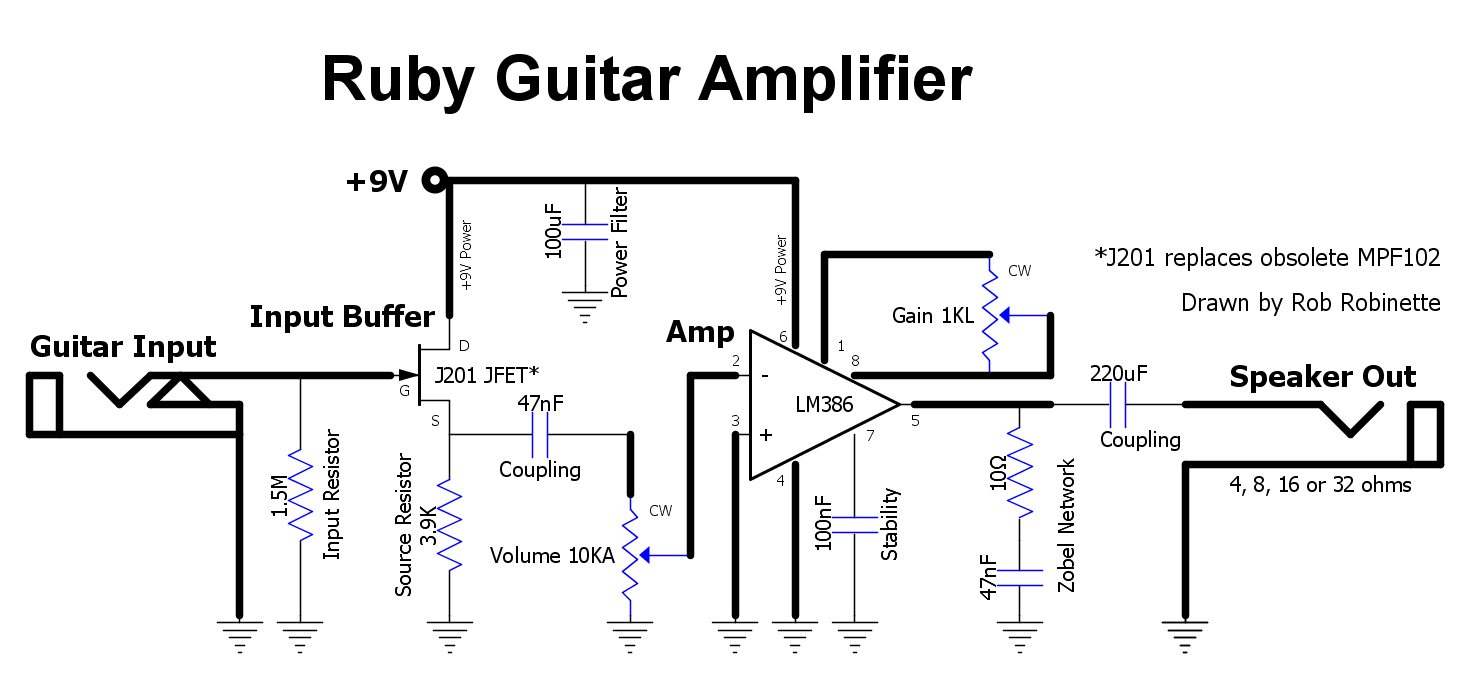
The J201 JFET (Junction gate Field Effect Transistor) is an input buffer and keeps the LM386 amplifier from affecting the guitar circuit. The J201 transistor functions like a tube cathode follower and does not amplify the guitar signal. The original Ruby Amp design called for a now obsolete MPF102 transistor. The LM386 is a chip amp that performs the functions of the preamp, power amp and output transformer. The little LM386 supplies all the amplification.
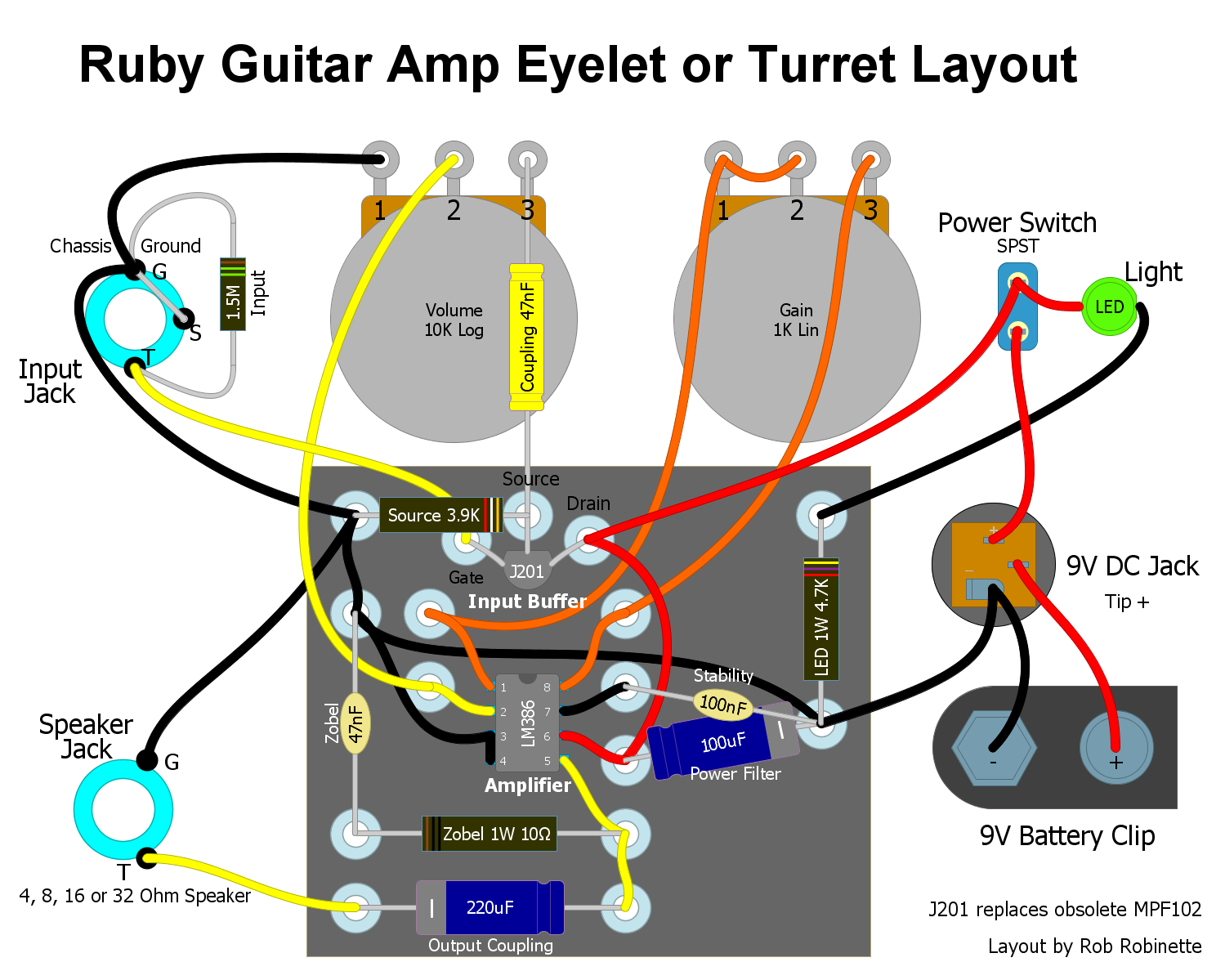
Carefully solder the J201 transistor directly to three eyelets/turrets. Use heat sink clips between the soldering iron and the J201's body to keep from damaging the transistor. Use an 8 pin DIP socket to mount the LM386 chip to the circuit board. Download the DIYLC layout file. If you want to build this amp using the above eyelet or turret board you can upload the Hoffman Circuit Board file to the Hoffman DIYLC layout analyzer and Doug will make the board for you.
Signal Path Through the Schematic
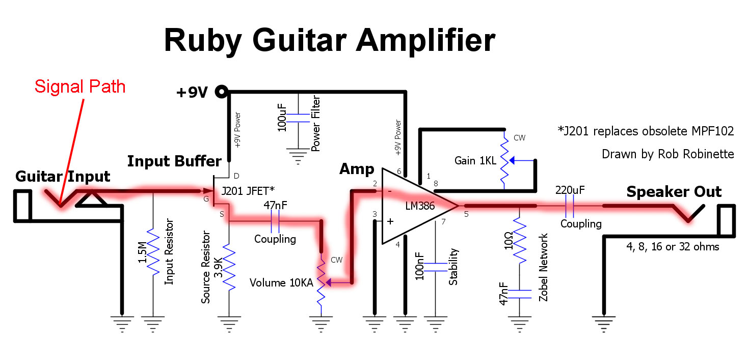
Guitar signal enters at the Input Jack at far left and flows directly to the transistor's gate where it controls the flow of current through the transistor and out the source lead. The transistor acts as a buffer to keep the LM386 amplifier from affecting the guitar circuit. The guitar signal then flows through a coupling cap to keep the transistor's DC voltage from flowing downstream into the Volume Pot. The Volume Pot's output goes directly into the LM386 amplifier's input pin 2. The Gain Pot is wired as a variable resistor and set's the LM386's gain factor from between 20 to 200. After amplification the LM386 sends the guitar audio out pin 5. The 10 ohm resistor & 47nF cap form a Zobel network to neutralize the effects of voice coil inductance. The signal goes through another coupling cap to keep any DC voltage from the LM386 out of the speaker. The output of the coupling cap is connected to the speaker jack tip.
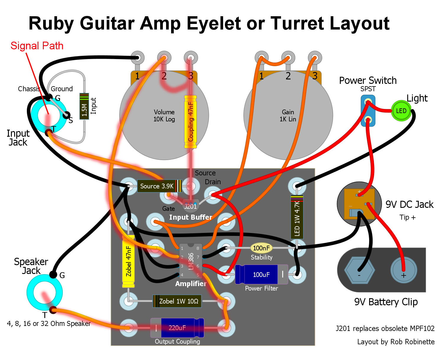
Signal Path Through the Layout
How It Works
The AC guitar audio signal enters at the Input Jack (upper left). The typical guitar signal is very weak at around 100 millivolts (.1 volts) AC (alternating current) or less.
The Input Resistor (mounted on the input jack) is 1.5M (megaohms) versus standard tube amp 1M. The 1.5M resistor better matches the J201 input buffer's needs. The Input Resistor sets the amplifier's input impedance and gives the J201 JFET's gate a ground reference.
From the input jack the guitar signal flows to the $3 J201 JFET Transistor's gate. The J201 transistor acts as an input buffer which functions like a tube cathode follower. The transistor's Gate functions similar to a tube control grid and controls the flow of current through the transistor. As the guitar signal fluctuates on the Gate, current flowing from the Source to the Drain fluctuates too. Note the original Ruby Amp design called for an MPF102 transistor which is now obsolete and no longer available. As an input buffer, the J201 transistor keeps the LM386 amplifier from affecting the guitar circuit. The Source Resistor attached to the transistor Source leg is similar to a cathode resistor and limits the flow of current through the transistor.
The guitar signal leaves the transistor's Source lead and flows through a standard Coupling Cap. The cap keeps DC voltage from the transistor from flowing downstream into the Volume Pot but it does allow the AC guitar signal to pass. You can bump this capacitor up to .1uF (micro Farad) for the Bassman Mod to allow more bass guitar frequencies to pass through the amp. The second half of the Bassman Mod is to place a 220pF (pico Farad) Bright Cap across the Volume Pot. A bright cap on a volume pot allows high frequencies to go around the volume pot to brighten lower volume settings. See the details of the Bassman Mod below.
The Volume Pot functions as a variable voltage divider to control how much guitar signal voltage gets to the LM386.
The LM386 Chip Amplifier
The $1 LM386 "chip amp" does all the amplification in the Ruby Amp. The LM386 is a specialized op amp that was designed for easy creation of various audio amplifiers. As you can see in the schematic below there's a lot going on inside that eight pin DIP chip. This little chip does everything a preamp tube + power tube + output transformer can do--it amplifies an input signal up to 200 times! Unlike a tube amplifier, the LM386 puts out enough signal current that it does not need an output transformer to drive a speaker coil.
Inside the Chip
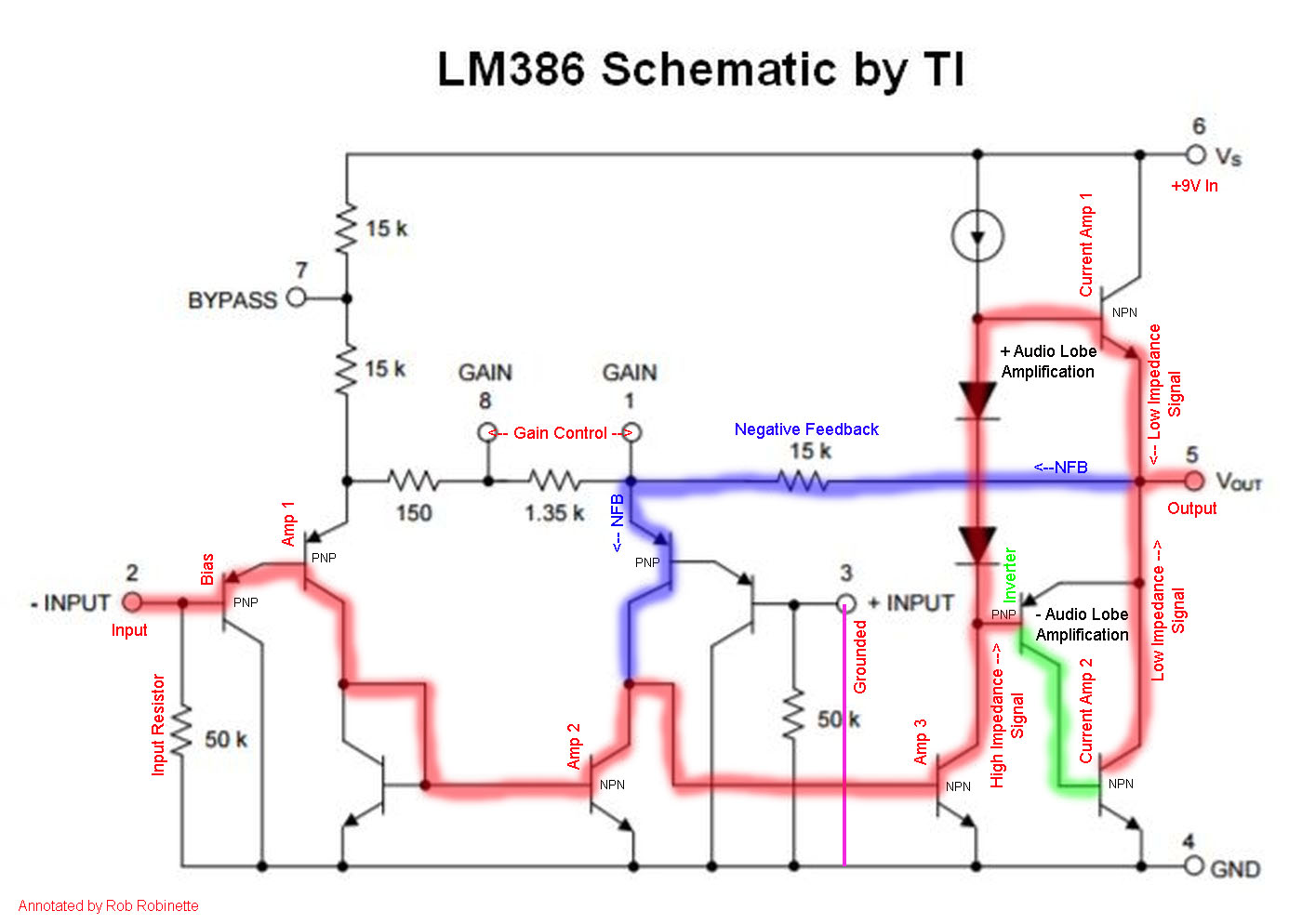
This is where the magic happens. Signal path shown in red, inverted signal in green and negative feedback loop shown in blue. Each of the 10 transistors inside the chip is the rough equivalent of a tube triode.
Referencing the schematic above, guitar audio enters the LM386 on the left at the pin 2 Input. The Input Resistor sets the LM386's input impedance to 50k ohms and gives the Bias stage's gate a ground reference. The first transistor sets the Bias voltage for the following stage Amp 1 which acts as the first stage of amplification. The amplified guitar signal then flows to the Amp 2 and Amp 3 gain stages for more guitar signal amplification. Amp 1, 2 and 3 function as voltage amplifiers creating a "thin" high impedance signal with lots of voltage swing but little current to back it up.
![]()
NPN transistor on the left, PNP on the right. A positive Base voltage on an NPN transistor will allow current to flow through the resistor. A negative Base voltage on a PNP transistor will allow current to flow.
Current Amp 1 amplifies the current of the positive voltage half (or lobe) of the guitar audio signal.
The Inverter flips the phase of the guitar signal going into Current Amp 2 where the negative half of the guitar signal is amplified. The two amplified signals are joined at the LM386 output pin 5. The two Current Amplifiers transform the "thin" high impedance guitar audio signal from the upstream voltage amplifiers into a "thick" low impedance signal with enough current to drive the speaker coil. An output transformer is not needed due to the low impedance signal output of the Current Amplifiers.
The LM386 has a negative feedback (NFB) loop that taps the output signal, attenuates it through the 15k Negative Feedback Resistor and injects it into the signal stream at the Pin 3 Input Amp 1 gain stage.
The LM386 can operate as a differential amplifier by using both the pin 2 (- Input) and pin 3 (+ Input) inputs but the Ruby Amp uses only the pin 2 input and grounds the pin 3 input so the differential amp feature is not used.
The LM386 is powered by 9 volt DC connected to pin 6. A 100uF Power Filter Capacitor is also connected to pin 6. The filter cap removes noise and hum that may enter through the 9v wall wart power supply.
The 100nF (nano Farad) Stability Cap connected to the LM386 pin 7 acts as a preamp power node filter to remove frequencies above human hearing to prevent amplifier oscillation.
The LM386's power rail consists of B+1 voltage (9v) entering at pin 6 which has the external 100uF filter cap attached. B+1 powers the Power Amp and Output section of the amp. B+1 voltage flows through a 15k resistor and gets filtered with the external 100nF filter cap creating B+2 voltage to power the Preamp section of the chip.
The chip's gain or amplification factor is controlled by the Gain Pot's resistance between pins 1 and 8. Short pin 1 to 8 and you get maximum gain of 200 times the input. Connect pins 1 and 8 with 10k (kilo ohms) of resistance and gain drops to around 20.
If you build a Ruby be sure and use an 8 pin DIP socket to mount the LM386 so you don't have to solder the LM386's legs which can easily lead to a damaged chip. You can glue the DIP socket directly to the circuit board and solder the output wires directly to the socket's legs. Don't insert the LM386 into the socket until you are finished soldering the DIP socket.
It was nice of Texas Instruments to pack 10 transistor amplifiers and other components into a nice little $1 eight pin DIP.
The guitar signal leaves the LM386 at pin 5 and encounters the 10 ohm resistor and 47nF cap that form a Zobel Network which helps neutralize the effects of voice coil inductance.
The guitar signal then flows through the Output Coupling Cap which keeps any DC voltage from the LM386 out of the speaker. The output of the coupling cap connects to the speaker jack tip.
The amplifier's voltage and current flow through the speaker coil which generates a magnetic field that interacts with the speaker magnet and causes the speaker cone to move in and out creating air pressure waves that our ears interpret as the sweet sound of electric guitar.
Ruby Amp Bassman Mod

Change the 47nF (.047uF) Coupling Cap to a two times larger .1uF cap for added bass. Add a 220pF Bright Cap to the Volume Pot to keep the tone from getting too dark at low volume. The Bright Cap allows high frequencies to go around the Volume Pot resistance. The result is a deeper, meatier, more 5F6A Bassman-like tone.
References
RCA Corporation, RCA Receiving Tube Manual, RC30.
Merlin Blencowe, Designing Tube Preamps for Guitar and Bass, 2nd Edition.
Merlin Blencowe, Designing High-Fidelity Tube Preamps
Morgan Jones, Valve Amplifiers, 4th Edition.
Richard Kuehnel, Circuit Analysis of a Legendary Tube Amplifier: The Fender Bassman 5F6-A, 3rd Edition.
Richard Kuehnel, Vacuum Tube Circuit Design: Guitar Amplifier Preamps, 2nd Edition.
Richard Kuehnel, Vacuum Tube Circuit Design: Guitar Amplifier Power Amps
Robert C. Megantz, Design and Construction of Tube Guitar Amplifiers
Neumann & Irving, Guitar Amplifier Overdrive, A Visual Tour It's fairly technical but it's the only book written specifically about guitar amplifier overdrive. It includes many graphs to help make the material easier to understand.
T.E. Rutt, Vacuum Tube Triode Nonlinearity as Part of The Electric Guitar Sound