Widowmaker Amps
By Rob Robinette
Many 1940's and 50's radios powered their tube circuits directly from mains (wall receptacle) voltage without a power transformer and their chassis was connected directly to one of the two power cord wires. When the radio shown below is plugged in correctly with the mains hot to the rectifier plate the amp is relatively safe with the chassis connected directly to the mains neutral (ground) wire. But turn the power cord plug around and you have full mains voltage and current on the chassis. This is why these types of devices are called "widowmakers". The radio will function with the power cord plugged in either way but it will usually receive better with less noise when the chassis is connected to neutral.
Please consider that after you spend a significant amount of money for an isolation transformer the cost of updating a widowmaker can exceed the value of the amp and they're not great amps to begin with.
True "Widowmaker" All American Five Radio Receiver
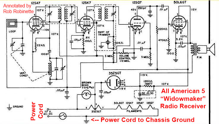
The All American Five radio receiver was very popular in the 1940s and '50s. The radio is wired as a true widowmaker--with one leg of the power cord connected directly to the radio chassis (above bottom center). If the power cord was plugged in "backwards" the radio would still function but the chassis would be hot with full mains voltage and amperage. The chassis was insulated from the user to prevent shocks but the metal screws on the bottom of the radio were exposed and present an extreme shock hazard.
I have seen only one guitar amplifier schematic which shows a power cord (mains) wire connected directly to the chassis like the All American Five radio receiver above.
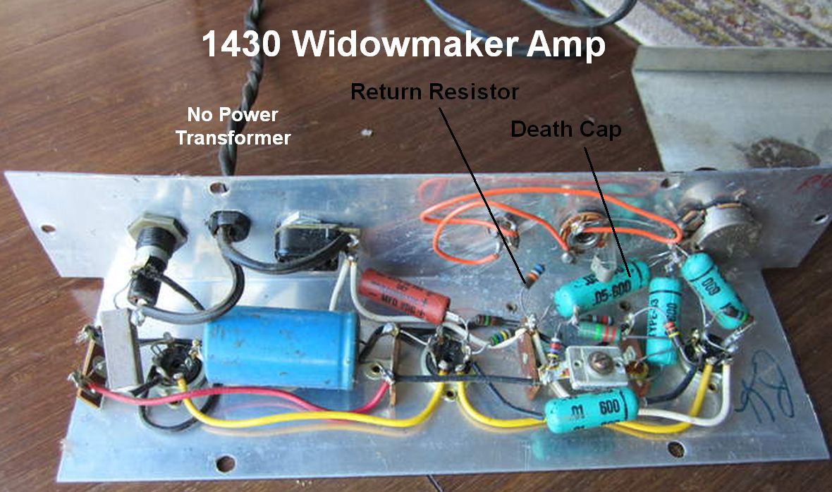
Silvertone 1430 "Widowmaker" Guitar Amplifier
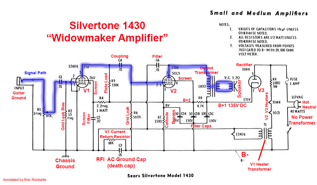
Notice how the power cord is not connected directly to the amplifier's chassis. The chassis ground is on the other side of the RFI (radio frequency interference) AC Ground Cap or "death cap". It provides an AC ground to the chassis so the chassis will block RFI and hum. The V1 Current Return Resistor is also connected to the chassis and allows a return path for V1 cathode current. When plugged in correctly there will be no voltage on the chassis. If the amp is plugged in "backwards" the amp will still function but the chassis will have 125 volts AC mains voltage on it but it will be limited to 4.2ma (2.4ma through the death cap + 1.8ma by the Return Resistor)--pretty much the same as any amp with a death cap and two prong power cord--so a player could receive a painful but mild shock.
The Silvertone 1430 shown above does not have its chassis tied directly to the mains like the All American Five radio. It uses an "RFI AC Ground Cap" (death cap) to connect a power cord wire to the chassis to make the chassis an RFI shield. They're called "death caps" because if they fail as a short they will electrify the chassis with full mains power. The 1430 also has a "V1 Current Return Resistor" to allow V1's cathode current to return to the mains' neutral wire. These two components isolate the chassis and guitar from the mains neutral and hot. Every widowmaker guitar amp and schematic I have seen except one uses a death cap and return resistor like the 1430 shown above.
Like all amps with a death cap, the 1430 will usually have less noise and hum when the amp is plugged in with the neutral wire connected to the RFI AC Ground Cap. This gives the chassis an AC signal ground which allows the chassis and guitar cable to act as an RFI shield.
These amps use mains power of 117 volts to power the tube heaters. The heater voltage required for each tube is the first two digits of the tube type: Preamp tube 12AU7 (can be wired for 6.3v or 12.6v) needs 12.6 volts of heater voltage, power tube 50C5 needs 50v and the rectifier tube 35W4 needs 35v. 12.6 + 50 + 35 = 97.6 volts so the design is 9.4 volts short of the 117 mains voltage. Resistor R9 100 ohm and 5 watts is a heater voltage dropper. It drops the last 9.4 volts to equal 117 volts. When you see a tube amp or radio that has tubes with high values for the first two digits that is a clue that it is probably a transformer-less widowmaker.
Another point of interest is the V1 heater transformer shown on the schematic above at lower right. The transformer is a safety feature that isolates the V1 heater circuit to prevent shock in case the V1 heater shorts to the cathode which is connected to the chassis. I did find one widowmaker guitar amp, the Magnatone 107 (schematic below), that does not have a V1 heater transformer. Ironically the schematic has a big "UL" Underwriter Laboratory safety stamp. The 107's V1 heater circuit is powered directly by mains voltage like V2.
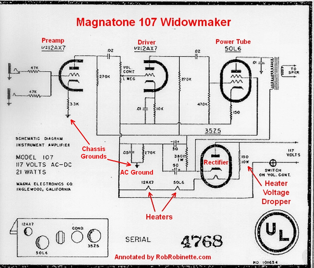
Note the lack of a V1 heater transformer. The V1 heater circuit is powered directly by mains voltage like V2. Note the .05uF cap in parallel with the 170k resistor (near center of schematic) are the RFI AC ground cap (death cap) and V1 Current Return Resistor.
Like any other amp with a two prong power cord and a "death cap" there is a risk of electrocution if the death cap fails as a short. With a shorted cap the chassis and guitar strings will become electrified with full mains power if the power plug is plugged in backwards.
Since the only chassis ground comes from the death cap there is no chassis safety ground. If an AC or DC hot wire comes loose inside the chassis and makes contact with the chassis it will electrify the chassis and guitar strings. With no safety ground the amp will simply sit there and wait for someone to touch the amp or guitar to deliver a very dangerous shock. But again, this is true of any amp with a two prong power cord and a death cap.
With a "normal" amp with a power transformer we can remove its death cap and install a three prong power cord to ground the chassis. The problem with power transformer-less widowmaker amps is if we install a three prong power cord and remove the death cap then V1's DC return current will flow through the chassis and safety ground while the rest of the amp would return its DC current to the mains neutral wire. It's true the neutral and safety ground wires are tied together at the building's service entrance but a hum inducing ground loop is very likely to be encountered.
After adding an isolation transformer and three prong power cord we can replace the death cap and Return Resistor with a jumper wire to unify the amp ground circuit.
Converting a Widowmaker Into a Safe, Normal Amp
An isolation transformer has to be used in a widowmaker to allow a "normal" and safe unified chassis grounding scheme. Because the isolation transformer has to handle both high voltage and heater current you'll need a larger than expected isolation transformer. Also many of these amps use half-wave rectifiers so you need to almost double the size of the isolation transformer. For this three tube 1430 amp I would use a Triode Magnetics N-53MG rated at 85 watts and 740 milliamps. That sounds like a lot but remember the tube heaters will be powered by this transformer too.
I have had people ask, "Why can't we just install a modern power transformer to make a widowmaker safe?" The reason is the tube heater circuit in these radios need mains voltage of 117 volts. The amp can't use the typical 6.3v of heater voltage supplied by modern tube amp power transformers.
To make an amplifier without a main power transformer (widowmaker) safe do the following:
1. Remove the two prong power cord.
2. Connect a three prong power cord: safety ground to the chassis, Hot to fuse center terminal, Neutral to one of the isolation transformer primary (input) wires.
3. Connect the other isolation transformer primary wire to one of the power switch terminals.
4. Connect the fuse side terminal to the other power switch terminal. This will wire the power cord hot wire so that it goes through the fuse first, then through the power switch, then through the isolation transformer primary.
5. Connect the isolation transformer secondary (output wires): one to chassis ground (should be separate from the safety chassis ground) and the other wire to the original fuse side terminal wire.
6. Replace the RFI AC Ground Cap (death cap) and the V1 Return Resistor with a jumper to chassis ground.
The removal of the death cap and Return Resistor and the addition of an isolation transformer and three prong cord are the only way to make these widowmaker amps as safe as any other modern amplifier.
See the Death Cap and Ground Switch page for more info.
Isolation Transformer For Amp Repair
Many budding amplifier techs are confused about the function of an isolation transformer. The purpose of an isolation transformer for amp repair purposes is to isolate the mains voltage potential in the amp from earth ground.
With a properly wired isolation transformer you can hold on to an earth ground rod in one hand and touch high voltage AC or DC in the amp with no effect. But if you touch the amp's hot and neutral wires you will still get shocked but the amperage is limited to what the isolation transformer can pass which is still enough to kill you many times over.
An isolation transformer is a good idea when using or working on widowmaker amps and radios but for normal, non-widowmaker amps and general electronic repair I don't recommend using an isolation transformer.
You can still get shocked by DC when using an isolation transformer. Since the power transformer high voltage secondary is referenced to the chassis via a center tap or rectifier bridge, touching the chassis and a DC voltage will cause a shock.
If the amp safety ground and chassis are connected to mains ground then you lose all DC isolation. You're still protected from mains AC but if you touch something that is grounded and touch DC in the amp you will get shocked. So if you use an isolation transformer you want the amp safety and chassis ground to float. Be aware that with a floating ground the chassis will lose it's RFI shielding properties so the amp may be noisier when using an isolation transformer.
When using an isolation transformer the mains AC in the amp can't shock you unless you touch the hot and neutral wires simultaneously but the DC is as strong and dangerous as ever. This and the loss of RFI shielding are why I don't bother using an isolation transformer for amplifier work.
References
RCA Corporation, RCA Receiving Tube Manual, RC30.
Merlin Blencowe, Designing Tube Preamps for Guitar and Bass, 2nd Edition.
Merlin Blencowe, Designing High-Fidelity Tube Preamps
Morgan Jones, Valve Amplifiers, 4th Edition.
Richard Kuehnel, Circuit Analysis of a Legendary Tube Amplifier: The Fender Bassman 5F6-A, 3rd Edition.
Richard Kuehnel, Vacuum Tube Circuit Design: Guitar Amplifier Preamps, 2nd Edition.
Richard Kuehnel, Vacuum Tube Circuit Design: Guitar Amplifier Power Amps
Robert C. Megantz, Design and Construction of Tube Guitar Amplifiers
Neumann & Irving, Guitar Amplifier Overdrive, A Visual Tour It's fairly technical but it's the only book written specifically about guitar amplifier overdrive. It includes many graphs to help make the material easier to understand.
T.E. Rutt, Vacuum Tube Triode Nonlinearity as Part of The Electric Guitar Sound
[ How Tube Amps Work ] [ How the 5E3 Deluxe Works ] [ 5E3 Deluxe Mods ] [ Deluxe Models ] [ Amp Troubleshooting ] [ 5F6A Bassman Mods and Info ] [ How the AB763 Deluxe Reverb Works ] [ AB763 Mods ] [ DRRI & 68 CDR Mods ] [ Tube Bias Calculator ] [ Overdrive ] [ Deluxe Micro Amp ] [ Bassman Micro Amp ] [ Champ Micro Amp ] [ My 5E3 Build ] [ Reverb & Tremolo ] [ SixShooter ] [ Spice Analysis ] [ VHT Special 6 Ultra Mods ] [ Telecaster Mods ] [ Android Tube Bias Calculator App ] [ The Trainwreck Pages ] [ Fender Input Jacks ] [ B9A Prototype Board ]