5E3 Deluxe & 5F11 Vibrolux Point to Point
This point-to-point (PTP or P2P) layout is intended for a blank Hammond style chassis or a "cake pan" build. You've got to keep everything pretty close together to make PTP work. Keep in mind you can build in "3D" with point-to-point and elevate some components up, over the top to avoid component crowding.
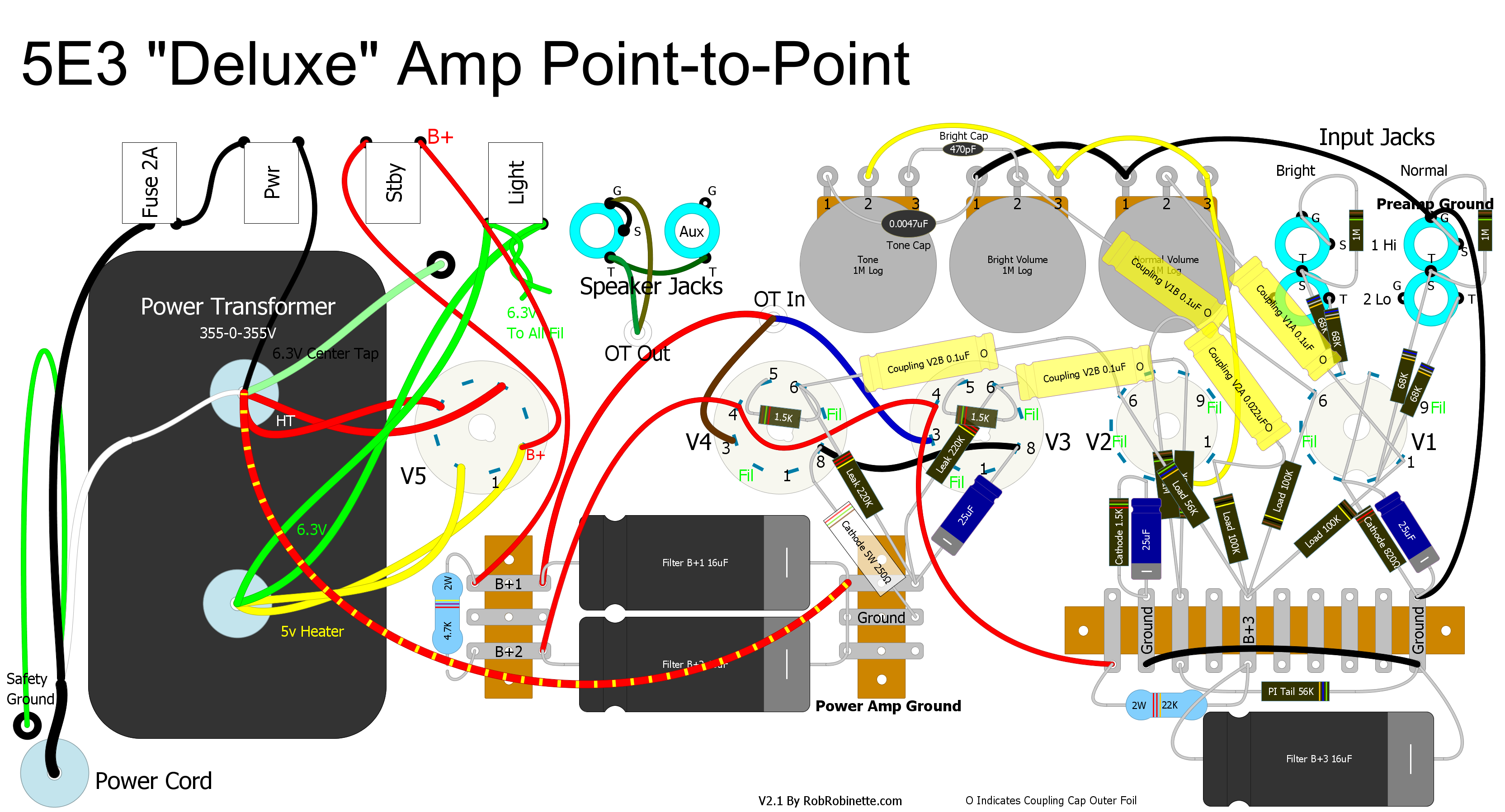
If you want to build your 5E3 Deluxe Old, Old School. Point-to-point wiring minimizes wires by using components to make connections when possible. Click on the layout to see the very large, full size layout. Components are anchored to the chassis with terminal tag strips.
Note the input jacks and volume pots need to be close to V1, that's your highest priority when setting up your chassis. If the span is too great you can put a tag strip between them to support the component and use a wire to make the rest of the run.
If you use a stand up power transformer you can mount it on top of the chassis (opposite side as shown above) for some additional room.
I don't show the heater wiring in the layout but for point-to-point builds I like to "fly" the heater wiring. Elevate the heater wiring above the circuit and drop leads down to the tube sockets. Take a look at Fender blackface and silverface heater wiring for examples. If you do plan to fly the heater wires then wire them in last after all the components are mounted.
Mount the power transformer on the opposite end of the chassis from the input jacks. Mount the output transformer next. It can be mounted near the power tubes but try to keep it away from the preamp tubes.
Note that some tag strips ground their center terminal to their chassis hold down bolt so take a close look at your strips before you mount them and avoid the grounded terminal unless you need a ground connection.

Guitar signal enters at the Bright Hi input jack at upper right. The signal splits and flows through both 68k grid stopper resistors to tube V1 pin 7 (preamp V1B grid). The signal leaves V1 through pin 6 (V1B plate) and a .01uF coupling cap to the Bright Volume pot. The coupling cap prevents high voltage DC on the plate from getting through to the volume and tone controls. The volume pot and tone controls bleed guitar signal to ground to control the volume and darken the tone. The guitar signal leaves the control circuit through the Normal Volume pot pin 3 and flows down to V2 pin 2 (preamp V2A grid). The signal leaves the tube via pin 1 (V2A plate) and flows through a coupling cap to the other side of tube V2, pin 7 (V2B grid). The coupling cap keeps high voltage DC off the V2B grid. V2B is the phase inverter and it splits the guitar signal in two. One signal leaves through pin 6 (V2B plate) and flows through a coupling cap to power tube V4 pin 6. A second, opposite phase signal flows out of V2B pin 8 (cathode) and flows through a coupling cap to power tube V3 pin 6. The power tubes' pin 6 has no internal connection and serves only to hold the 1.5K grid stopper resistor. The signal flows through the grid stopper resistor and into the power tubes at pin 5 (grid). The guitar signal leaves the power tubes via pin 3 (plate) and flows into the output transformer primary winding. The signal couples with the output transformer secondary and flows out to the speaker jack.
Simplified Point-to-Point With No Standby Switch
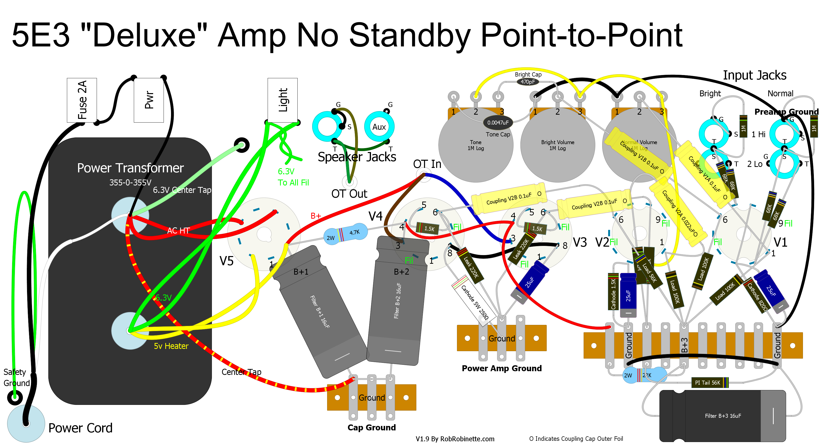
The worthless standby switch has been removed which allowed some simplification and optimization. I used a simple three-point grounding scheme with the first two filter caps' ground isolated. The "Cap Ground" and "Power Amp Ground" tag strips are grounded to the chassis. The preamp ground at lower right is grounded through the black wire connected to the Normal Hi input jack at upper right--the tag strip's center ground terminal is not used.
Aaron's Single Channel Point-to-Point 5E3
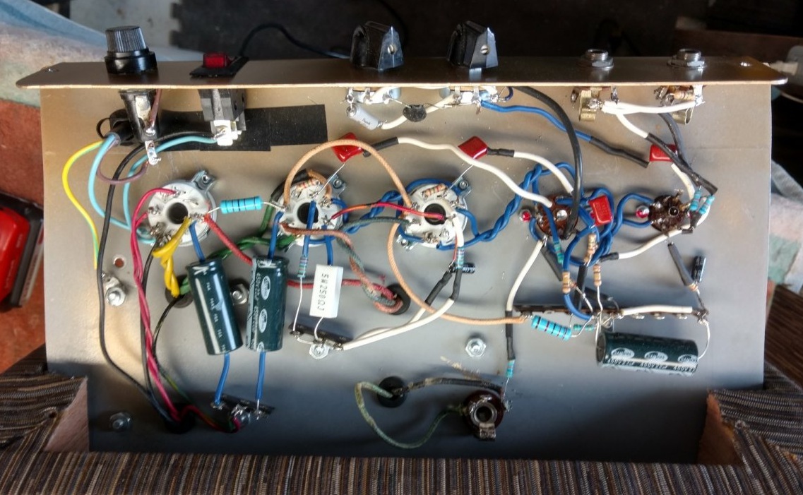
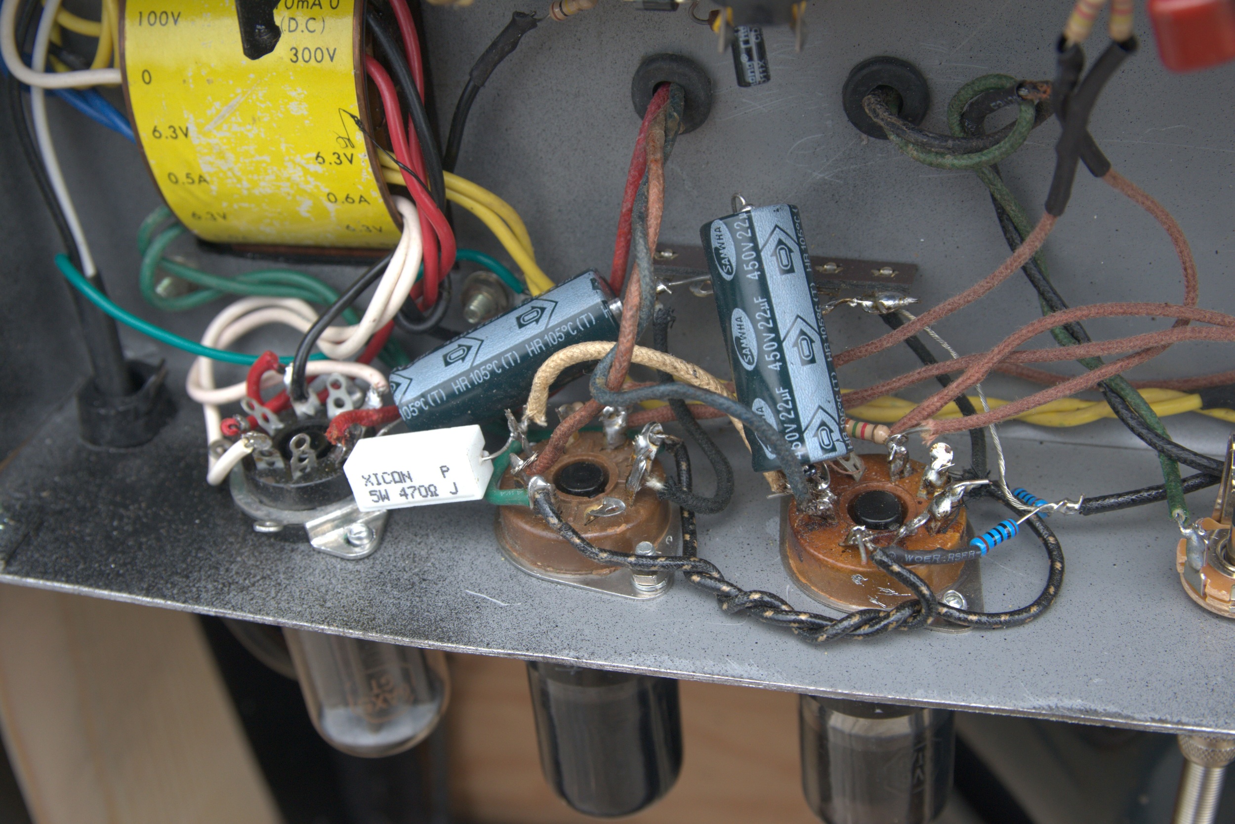
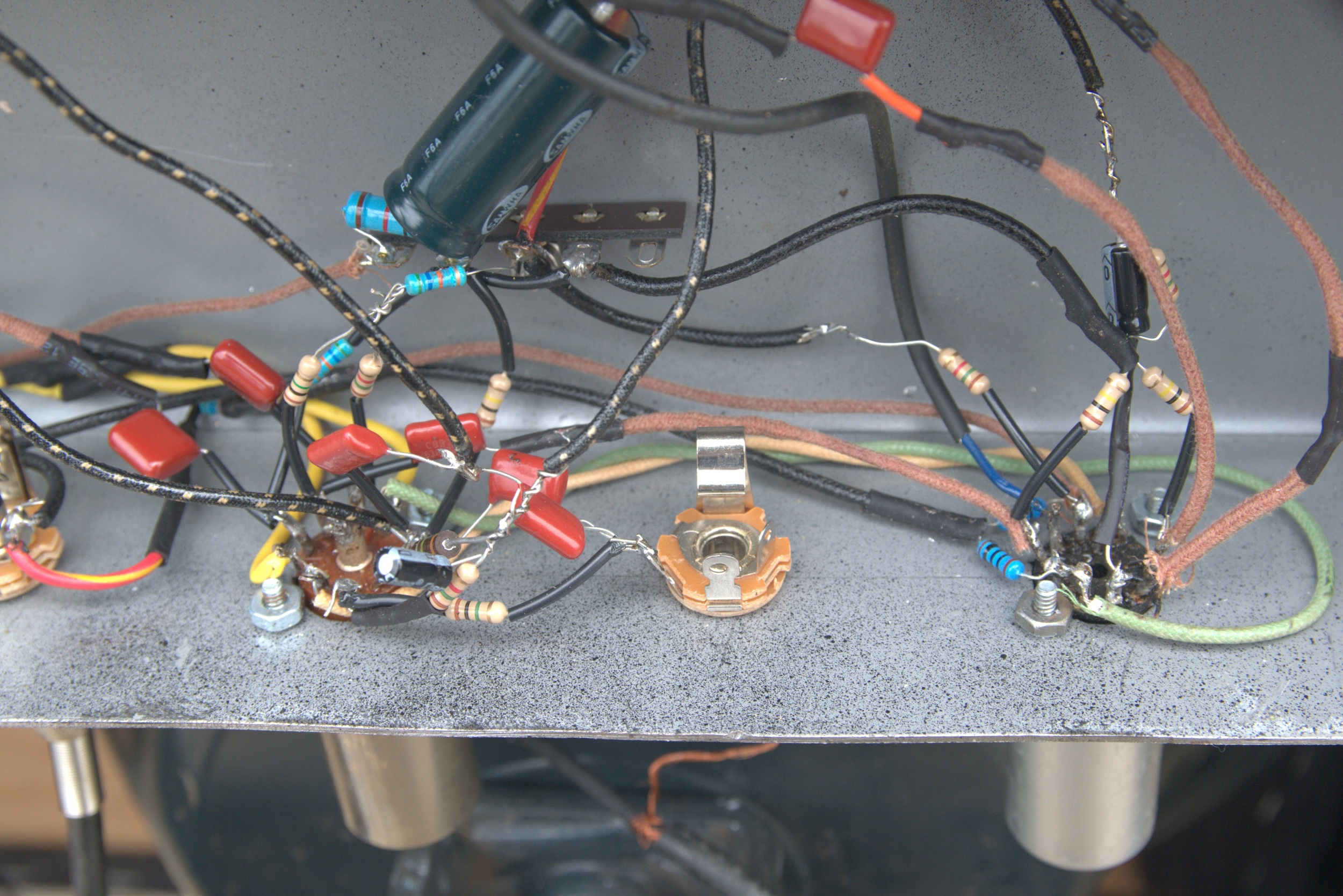
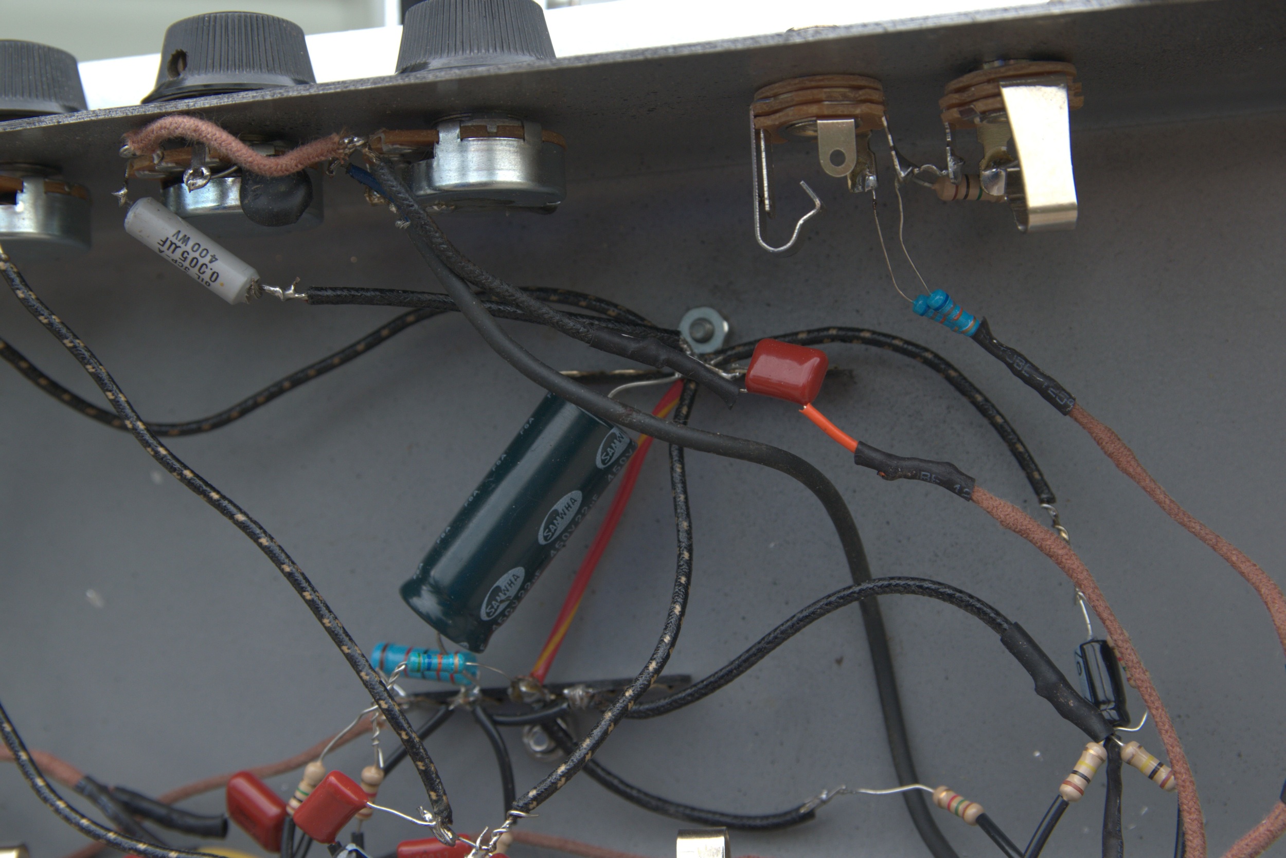
Aaron's Tweed Vibrolux 5F11 Point-to-Point
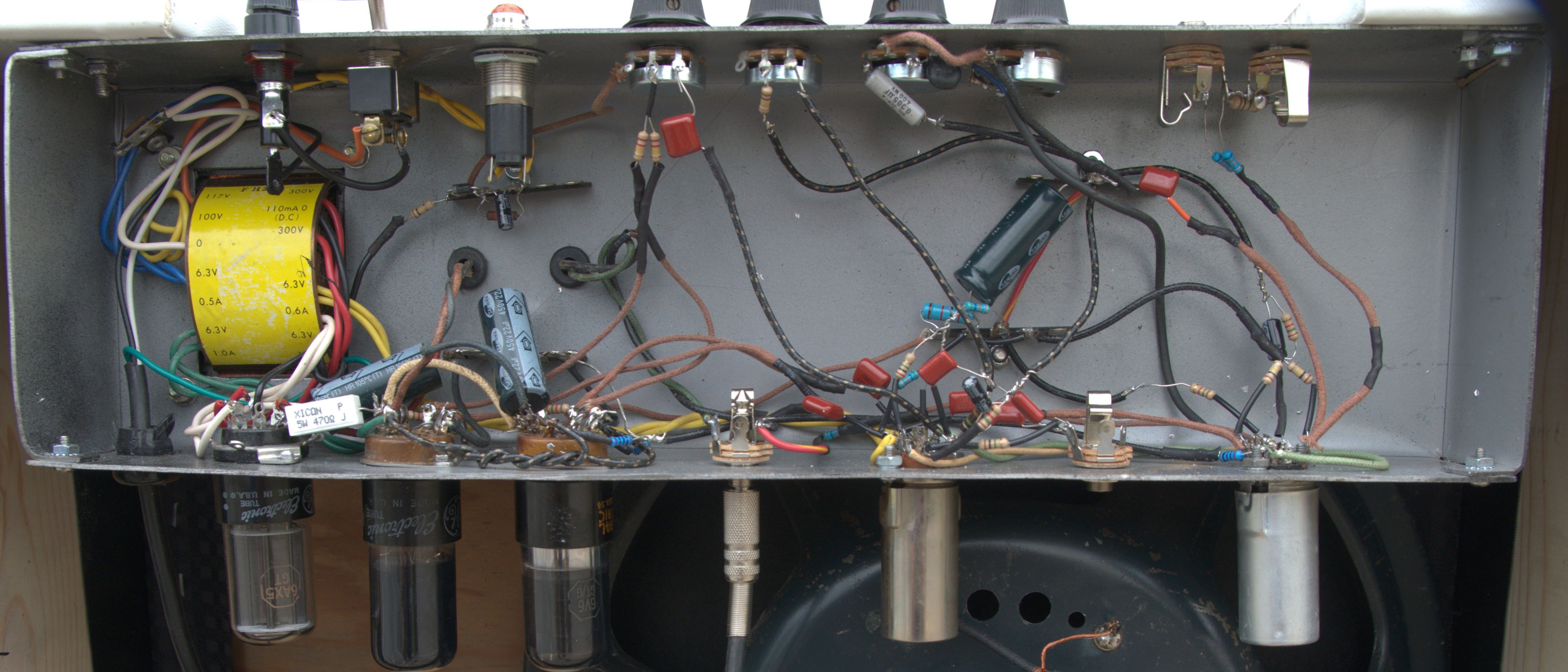
Note: This 5F11 amp uses a 6AX5 6.3v rectifier. Click the image to see the giant version for detail view.
More 5F11 Pics
Comments and corrections are always welcome at robinette at comcast dot net.
[ How Tube Amps Work ] [ How the 5E3 Deluxe Works ] [ 5E3 Deluxe Mods ] [ Deluxe Models ] [ Amp Troubleshooting ] [ 5F6A Bassman Mods and Info ] [ How the AB763 Deluxe Reverb Works ] [ AB763 Mods ] [ DRRI & 68 CDR Mods ] [ Tube Bias Calculator ] [ Overdrive ] [ Deluxe Micro Amp ] [ Bassman Micro Amp ] [ Champ Micro Amp ] [ My 5E3 Build ] [ Reverb & Tremolo ] [ SixShooter ] [ Spice Analysis ] [ VHT Special 6 Ultra Mods ] [ Telecaster Mods ] [ Android Tube Bias Calculator App ] [ The Trainwreck Pages ] [ Fender Input Jacks ] [ B9A Prototype Board ]