Enter Voltage Across Cathode Resistor:
DC volts Voltage drop across the
cathode resistor.
Tube Dissipation Using Plate Current
Use this calculator when you measure the actual plate
current. You must enter Tube Type and
Plate-to-Cathode Voltage above before
calculating Tube Dissipation.
Enter Plate Current:
DC milliampsNote: You must re-calculate after changing values by clicking any
Calculate button. Tube Type
and Plate-to-Cathode Voltage must be entered
for all calculations on this webpage.
WARNING: A
tube amplifier chassis contains lethal high voltage even when unplugged--sometimes
over 700 volts AC and 500 volts DC. If you have not been trained to work with
high voltage then have an amp technician service your amp. Never touch the
amplifier chassis with one hand while probing with the other hand because a
lethal shock can run between your arms through your heart.
Use just one hand when working on a powered amp. See more
tube amplifier safety info here.
Tube Bias Calculator Instructions & Help
Enter values in blue
and click any Calculate button.
Select the Tube Type
from the scrolling list. If your tube isn't listed then pick one with
the same Max Dissipation Rate which is shown to the right in the tube
list.
Enter the Plate-to-Cathode Voltage
which is measured between the
plate and cathode tube socket pins, not between the plate and ground.
You measure it by placing the red + multimeter probe on the plate pin
and the black - probe on the cathode pin.
You can also calculate the Plate-to-Cathode Voltage by
subtracting the voltage measured at the cathode pin from the voltage
measured at the plate pin. See this link for
more info on measuring
and adjusting bias.
For octal (8-pin) tubes the plate is pin 3 and the cathode is
pin 8. For 9-Pin power tubes like the EL84 the plate is pin 7 and the cathode
is pin 3. For 9-Pin preamp tubes like the 12AX7 the plates are pins 1
and 6 and the cathodes are pins 3 and 8 (measure between pins 1 and 3
for A; 6 and 8 for B).
Octal Tube Socket Numbers
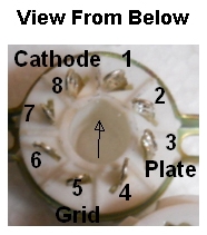
Plate is pin 3 and Cathode is pin 8. Arrow points to the insertion index notch.
Click any
Calculate button to see the recommended tube bias currents in milliamps. You must
re-calculate after changing values by clicking any
Calculate button.
Tube Type and
Plate-to-Cathode
Voltage must be entered for all calculations on this webpage.
Usually single power tube amps are Class A
and amps with two or more power tubes are Class AB. Amps with power tube
cathode resistors greater than 10 ohms are usually cathode biased.
The Fender 5F1 Champ is a Class A cathode biased amp. The Fender 5E3
Deluxe is a cathode biased Class AB amp. The Fender 5F6A Bassman
and most Marshall amps are fixed bias Class AB amps. Fixed bias amps have a
bias circuit that puts a negative voltage on the power tube grid. The grid
of cathode biased amps will be at 0 volts.
Tubes have a maximum dissipation rating in watts for how much power (and therefore heat)
they can deal with so we adjust the tube's bias voltage (voltage
between the grid and cathode) to keep the bias current below the
tube's max dissipation (power & heat) rating. If you bias
your amp too hot you may shorten the life of your tubes but bias it too
cool and the amp may sound sterile.
Fixed bias amplifiers apply a steady (fixed) negative bias voltage
to the power tube grid and the cathode is connected directly to ground
(no cathode resistor). It is called 'fixed'
bias because the bias voltage does not fluctuate the way it does with
cathode bias.
Cathode bias
amplifiers use a cathode resistor to generate a positive bias voltage on
the cathode while the grid is grounded through a 'grid leak' resistor.
As the guitar signal causes the current flow through the cathode
resistor to fluctuate so does the voltage drop across the cathode
resistor (the bias voltage). Since the bias voltage fluctuates with the
input signal it is not 'fixed.'
Be aware the term plate voltage can have two
meanings. It can mean the actual voltage measured from the tube plate
pin to ground but when measuring tube bias it means the voltage difference between the
tube's plate and cathode. To avoid confusion I use the term
plate-to-cathode voltage. You can measure it directly by placing the
red + multimeter probe on the plate pin and the black - probe on the
cathode pin. You can also measure the plate voltage and the cathode
voltage separately then subtract the cathode voltage from the plate voltage to
get plate-to-cathode voltage.
Triode Tubes
Triode tubes do not have a screen so they do not have
any screen current to consider. The dissipation ratings for dual triodes
such as the 12A*7 family of tubes is listed as total dissipation using
both triodes. For a dual triode tube with both triodes used enter "1" in
the Enter Number of Tubes that share a cathode
resistor box. If you only use one triode of a dual triode tube you
will need to
double the displayed
dissipation %.
For example my Deluxe
Micro amp uses both triodes of a 12AU7 rated at 5.5 watts max
dissipation total and 2.75 watts per
triode. If the amp used only one
triode then the max dissipation would be 2.75 watts and I would multiply
the calculator's displayed dissipation % by 2.
Over Biased Red Plating
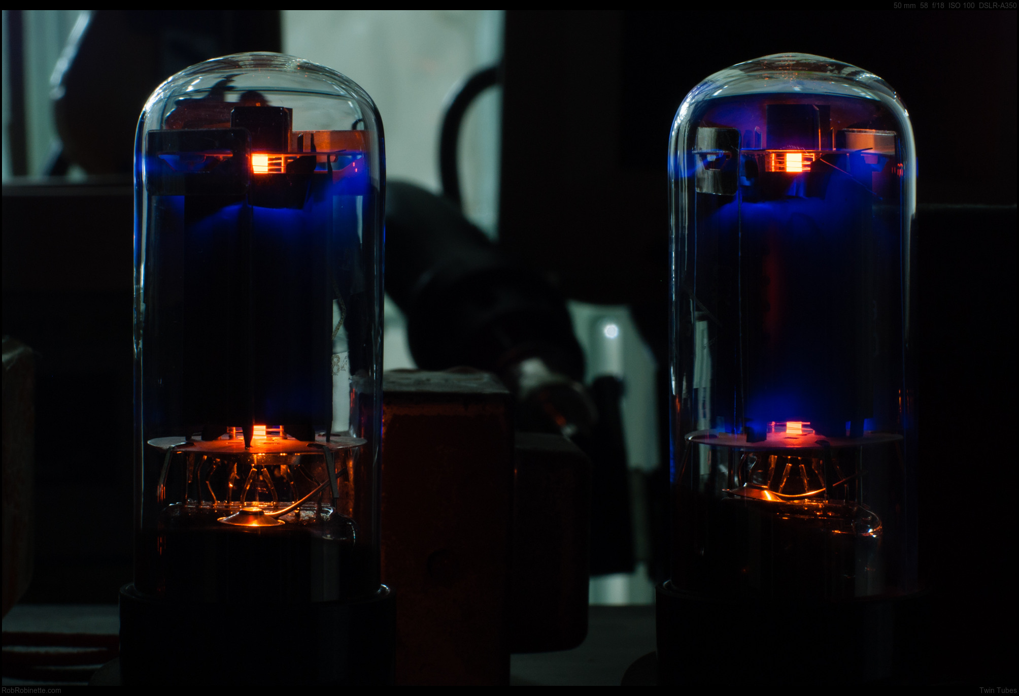
Notice the slight red glow in the middle of the right 6N3C power
tube? It's red plating due to a too hot bias. Photo by
Rob Robinette
How to Measure Bias
This webpage offers two ways to calculate
tube bias and plate dissipation.
For amps with cathode bias resistors you can simply
measure their voltage drop and use the
Tube Dissipation Using Cathode Resistor Voltage Drop
calculator. My recommended bias measurement method is the "Output
Transformer Resistance Method."
You measure the output transformer's voltage drop and resistance to calculate
the bias current.
You can also measure the actual plate current by shunting
the output transformer with a multimeter in the DC milliamps mode
and use
the Tube Dissipation Using Plate
Current calculator. This method is more dangerous
because when your meter probe touches high voltage your other meter probe will
also carry that high voltage so you must be very careful what those probes
touch.
To use the Tube Dissipation Using Cathode Resistor Voltage Drop
calculator enter your Tube
Type and
Plate-to-Cathode Voltage at the top of the page,
then
enter the Number of Tubes
that share a cathode resistor, the measured
Voltage Drop across the cathode resistor and the
Cathode Resistor's Ohm Value and
click Calculate.
If your amp has 1 ohm bias setting resistors then enter '1' into the
Cathode Resistor's Ohm Value field. You can get an accurate
resistance measurement of cathode resistors by turning the amp off and
simply measuring resistance across the cathode resistor. It's more
accurate to actually measure the resistor's ohm value rather than
relying on its marked rating. The calculator subtracts 5.5% of the
cathode current as screen current.
To measure voltage drop across the cathode resistor set
your multimeter for DC Volt measurement, clip the black probe to chassis
ground (so you can use just one hand to do the measurement) and put the red probe on the
tube socket cathode pin . You
can also put one probe on each leg of the cathode resistor. The
voltage shown on the meter is the 'voltage drop' (disregard any minus
sign).
Note that voltage measured at the cathode pin is the same as the voltage drop
across the cathode resistor so you don't have to actually put your meter
pins on the legs of the cathode resistor to measure its voltage drop.
You can get a more accurate bias measurement if you actually measure the
resistance of your cathode resistor. It may be marked as a 250 ohm
resistor but actually measure 238. To measure the cathode resistor turn
the amp off and measure the resistance from the tube cathode pin to
ground.
For fixed bias amps with no cathode
resistors you calculate the bias current by measuring the output
transformer's resistance and voltage or you can measure the actual plate current
then use
the Tube Dissipation Using Plate
Current calculator. Measuring the actual plate current by
using the "output transformer shunt method" is more difficult and dangerous than
the "output transformer resistance method or
using the cathode resistor voltage drop method. See my
Bias How-To for more info. After selecting your
Tube Type and entering your
Plate-to-Cathode Voltage at the top of the page simply enter your
Plate Current and click any
Calculate button.
I recommend you play your guitar through the amp every time you make a bias
adjustment. You may find you prefer a 'cool' or 'hot' bias with your
particular playing style,
guitar and amp. The amp's tone is what really matters so don't just set
a standard bias target like 70% for Class AB amps and forget it.
Your amp's "best" bias setting is pretty subjective so play it
while you adjust it.
See my How to Bias a Tube Amp
for more info.
If you prefer spreadsheets you can download the
Excel and
OpenOffice Tube Bias
spreadsheets.
I also have a free Android Tube Bias Calculator app available
here in the Google Play Store or just search the Google Play Store for "Rob Robinette."
Have comments, corrections or suggestions? Send them to robinette at comcast dot net.
By Rob Robinette
References
RCA Corporation,
RCA Receiving Tube Manual,
RC30.
Merlin Blencowe,
Designing Tube Preamps for Guitar and Bass, 2nd Edition.
Merlin Blencowe, Designing
High-Fidelity Tube Preamps
Morgan Jones,
Valve Amplifiers, 4th Edition.
Richard Kuehnel,
Circuit Analysis of a Legendary Tube Amplifier: The Fender Bassman 5F6-A,
3rd Edition.
Richard Kuehnel,
Vacuum Tube Circuit Design: Guitar Amplifier Preamps, 2nd Edition.
Richard Kuehnel,
Vacuum Tube Circuit Design: Guitar Amplifier Power Amps
Robert C. Megantz,
Design and Construction of Tube Guitar Amplifiers
Neumann &
Irving,
Guitar Amplifier Overdrive, A Visual Tour It's
fairly technical but it's the only book written specifically about guitar
amplifier overdrive. It includes many graphs to help make the material
easier to understand.
T.E. Rutt,
Vacuum Tube Triode
Nonlinearity as Part of The Electric Guitar Sound
[
How the 5E3 Deluxe
Works ] [
Deluxe Models ] [
DRRI & 68 CDR Mods ] [
Amp Troubleshooting ] [
My 5E3 Build ] [
Spice Analysis ] [
The Trainwreck Pages ] [ Fender Input Jacks
] [
B9A Prototype Boards ]