
How the Marshall Plexi, 2204 and JCM800 Amplifiers Work
By Rob Robinette
Keep in mind that Marshall made a lot of part substitutions and "upgrades" to these long production run amps so many parts, especially capacitors' component values can differ from these schematics. Also be advised that Marshall model numbers have nothing to do with the year the amp was introduced. If after looking at this page you feel you need some background information on how tube amps work see my How Tube Guitar Amps Work and How Vacuum Tubes Work pages.
Table of Contents
The Long Tail Pair Phase Inverter
Tweaking the Overdrive and Tone
Classic Marshall Amp Cheat Sheet
1959 Super Lead 100 Watt and 1987 Lead 50 Watt "Plexi" Preamp
The Marshall Plexi guitar amplifier was an evolution of their very successful Fender 5F6-A Bassman copy, the JTM45 but with just two preamp gain stages it can't really be considered a "high gain" amplifier.
The Plexi's topology is still very similar to the Fender 5F6-A Bassman. The guitar signal enters at left at the I "Bright" Channel input jack. The signal is amplified by the V1B preamp stage then flows through the Volume I pot to the V2A preamp then directly through DC coupling (no coupling cap) to the V2B cathode follower which supplies the tone stack with a low impedance signal to keep the tone stack from loading down the guitar signal. After the Tone Stack the signal goes into the Phase Inverter. The Phase Inverter creates two mirror image signals that are 180 degrees out of phase to feed to the Power Tubes.
The "Plexi" came with two distinctly voiced channels each with two inputs. These two channels parallel one another and meet up at the V2A second preamp gain stage. A common mod with these amps was to change the channels from parallel to series so the guitar signal went through both V1A and V1B before hitting the third V2A gain stage. These modded amps are where Marshall got the idea for the 2203 Master Volume preamp described below.
Each channel's High and Low jacks function just like the Fender standard four input circuit. The Low inputs have their guitar signal cut in half by forming a voltage divider with the two 68k Grid Stopper resistors. The High jack's input impedance is 1 megaohm while the Low jack's is 68k. The two very different input impedances can color the tone from the guitar's pickups so you should always try both the High and Low inputs to hear which sounds better with the guitar you're using. Humbuckers and hot pickups often sound better through the Low jacks. Both channels parallel one another and both go through two preamp gain stages before hitting the no-gain V2B cathode follower, Tone Stack and Phase Inverter. See How the TMB Tone Stack Works for more info.
The I "Bright" or "Lead" Channel signal is amplified by V1B (the B half of Valve 1) which has a cool bias from its 2.7k cathode resistor. Its small .68uF bypass cap boosts the gain of mid and high frequencies which reduces the Bright Channel's lower frequencies early in the circuit so it can focus on mids and highs that sound good when later stages push into heavy distortion. Because of this design the Bright or "Lead" Channel responds extremely well to boost and drive pedals. The Bright Channel's very small .0022uF coupling cap also limits bass frequencies and facilitates a cleaner, leaner overdrive tone.
The II "Normal" Channel signal is amplified by V1A (the A half of Valve 1) which has a warm bias from its 820 ohm cathode resistor. Its very large 330uF bypass cap boosts all guitar and bass frequencies for a rich full bodied tone. The Normal Channel's ten times larger .022uF coupling cap also helps preserve bass frequencies.
The large 470k Mixer Resistors interact with V2A's (the A half of Valve 2) Miller capacitance to roll off some high frequencies. That's why Marshall employed a 470pF Bright Cap or "treble peaker" around the Bright or "Lead" Channel's Mixer Resistor to preserve those high frequencies.
The Cathode Follower
The primary purpose of the Cathode Follower is to prevent the tone stack from loading down the high impedance guitar signal coming off V2A's plate. The Cathode Follower supplies a low impedance signal to the tone stack to keep the tone controls from affecting the amp's output volume too much. Amp users do not want the volume to drop when they roll off some bass.
But the Cathode Follower does much more than feed the tone stack. It is the first triode to go into overdrive and its interaction with the upstream gain stage adds a unique overdrive effect that limits clipping of both the positive and negative signal lobes. This is one of the "secret" reasons the Fender 5F6-A Bassman, Marshall JTM45, Plexi and Master Volume amps sound so good when pushed hard.
The Birth of the High Gain Amplifier
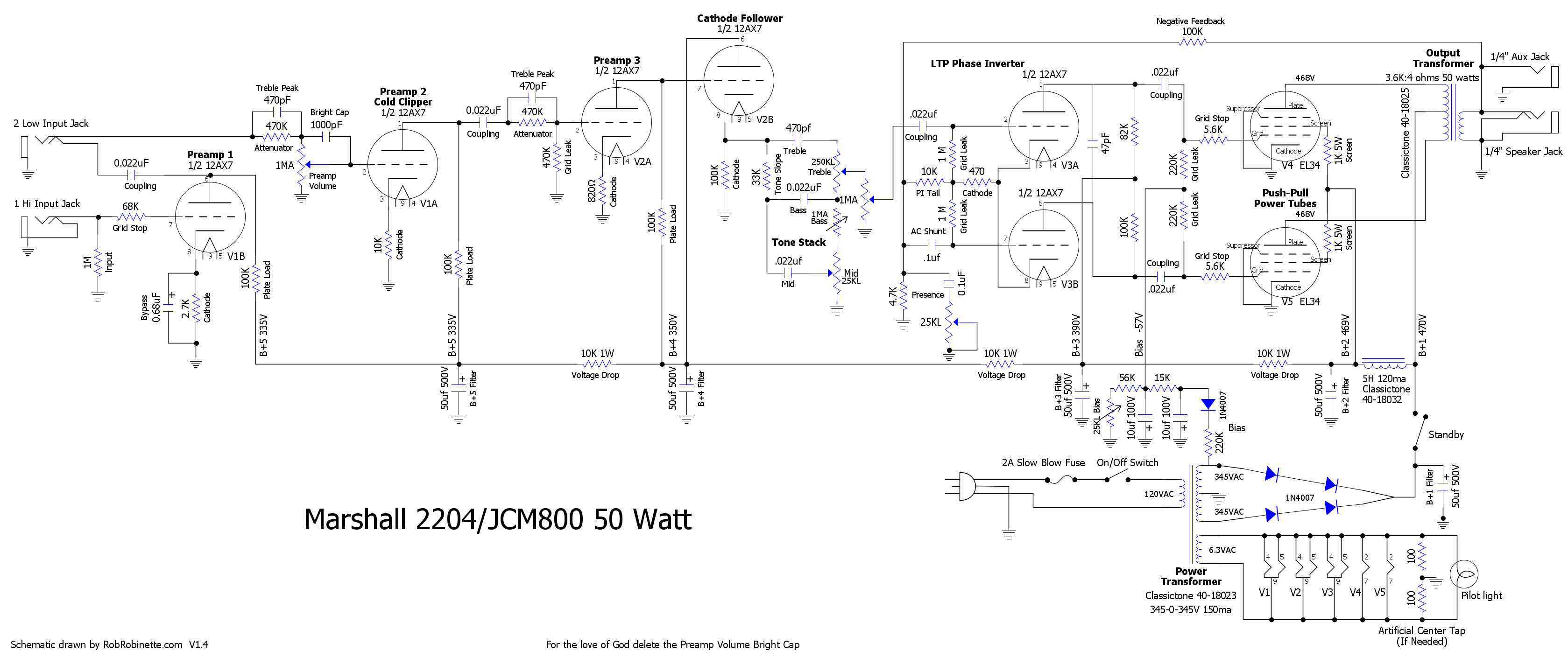
2203 Master Volume 100 Watt, 2204 50 Watt and JCM800 Lead Series Preamp
Introduced in 1974, the "Master Volume Lead" series amps were Marshall's first true high gain amplifiers. They cascaded the Plexi's bright channel into the normal channel, added a pre-phase inverter master volume and cold biased "cold clipper" gain stage and tweaked the resulting circuit for an aggressive but sweet overdrive tone.
The 2203 was a 100 watt head and the 2103 was a 100 watt 2x12 combo. The 2204 was a 50 watt head and the 2104 was a 50 watt 2x12 combo. The change from "2204 Master Volume" to JCM800 was mostly cosmetic and made for legal purposes at the end of the Rose-Morris distribution deal.
The guitar signal enters at far left at the High "Lead" Channel input jack. The signal is amplified by the V1B preamp stage then flows through the Preamp Volume pot to the V1A cold biased "cold clipper" gain stage which generates asymmetric clipping. The signal then flows through the V2A preamp then directly through DC coupling (no coupling cap) to the V2B cathode follower which supplies the tone stack with a low impedance signal to keep the tone stack from loading down the guitar signal. After the Tone Stack the signal goes through the Master Volume and into the Phase Inverter. The Phase Inverter creates two mirror image signals that are 180 degrees out of phase to feed to the Power Tubes.
The "High Sensitivity" or "Lead" Channel has an extra preamp gain stage compared to the Low Channel (described below). The guitar signal is amplified by V1B (one 12AX7 triode) which has a cool bias from its 2.7k cathode resistor. Its small .68uF bypass cap boosts the gain of mid and high frequencies which reduces the High Channel's lower frequencies early in the circuit so it can focus on mids and highs that sound good when later stages push into heavy distortion. The signal then flows through the Low Channel input jack (where the Low Channel input would start) to the Preamp Volume pot. The pot's output flows to the V1A "cold clipper" gain stage.
The Cold Clipper
The cold clipper is very important to these Marshall high gain amps' smooth overdrive tone. For minimum distortion a tube should be biased halfway between cutoff (when all electron flow is stopped) and saturation (when electron flow is maxed out). A 1.5k cathode resistor for a typical tube amp 12AX7 triode gain stage is very close to center bias. The cold clipper's very large 10k cathode resistor sets a cold bias that leaves little room on the shutoff side so the input signal can easily be clipped when the input signal's negative lobe on the grid reduces electron flow through the tube and electron flow is shutdown completely. This clipping is asymmetric because there's plenty of room on the saturation side of the bias point. Asymmetric clipping generates mostly sweet sounding 2nd harmonic distortion. The positive, saturation side of the guitar signal lobe isn't distorted and carries the original musical content.
The JMC800 uses a cold clipper stage with an unbypassed 10k cathode resistor. Soldano liked to use a more aggressive 39k cathode resistor for an even colder cold clipper. Note the following gain stage is biased warm with an 820 ohm cathode resistor. Since a guitar signal's phase if flipped after each gain stage putting a warm biased stage after the Cold Clipper helps keep the distortion asymmetrical by keeping the undistorted lobe clean.
Asymmetric clipping tends to sound smoother and creamier than symmetric clipping where both the + and - signal lobes are clipped equally. With asymmetric clipping one signal lobe carries the clean signal while the clipped lobe carries the distortion. The cold clipper generates early, relatively low volume, smooth, musical preamp distortion that can be controlled by the Master Volume for high gain tone at lower volume than their earlier non-master volume amps. Without the cold clipper stage the preamp would stay too clean and the amp would have to rely on distortion from the power amp making the Master Volume less useable. As the cold clipper distortion comes on it blends seamlessly into the downstream phase inverter and power tube distortion into a cacophony of delicious high gain tone.
The cold clipper's asymmetric output signal can be clipped in later gain stages at high volume levels but note the gain stage following the Cold Clipper is biased warm with an 820 ohm cathode resistor (V2A). Because a guitar signal's phase if flipped after each gain stage, putting a warm biased stage after the Cold Clipper helps keep the distortion asymmetric by keeping the guitar signal's undistorted lobe clean. The warm bias leaves more room on the cutoff side to reduce clipping to the undistorted signal lobe.
The cold clipper is also a relatively low gain stage compared to one with a fully bypassed cathode. Soldano used the cold clipper cathode resistor value to trim gain to make his preamp work as desired. The higher the resistance value the lower the gain. That's one of the reasons Soldano used such a very large (39k) cathode resistor in his cold clipper.
Marshall Cold Clipper Load Lines
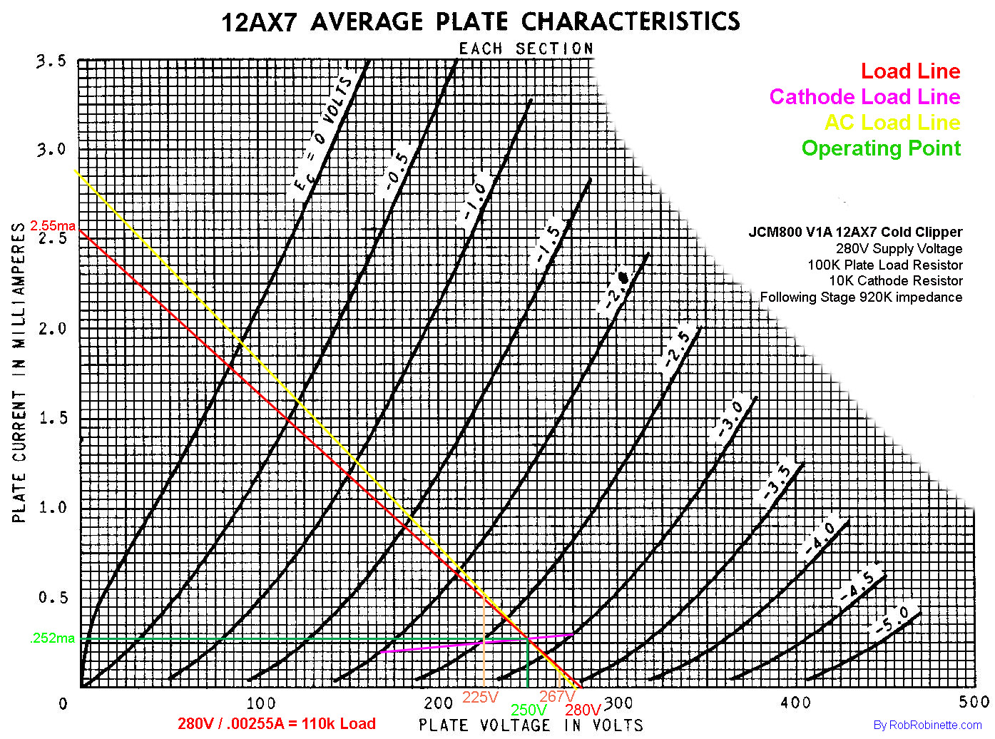
The operating point (intersection of green lines) is very low in the curvy end of the grid voltage lines so the negative half of the guitar audio signal is distorted even before clipping occurs. Signal clipping will occur with the negative lobe of the signal voltage much earlier than the positive lobe which will lead to early sweet sounding asymmetric cutoff clipping. For information on how these lines were charted see How to Draw Load Lines.
Cold Clipper Switch
This is a cool little mod that allows you to select a 10k Marshall Cold Clipper, Soldano 39k Clipper or aggressive grid clipping in the following stage.
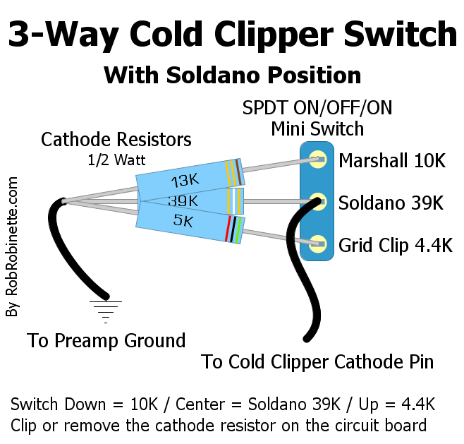
Down: Marshall 10k
Middle: Soldano 39k
Up: Grid clipping 4.4k
You can also put a cathode bypass cap across the 5k resistor to generate extreme grid clipping in the following stage with the switch in the "Grid Clip 4.4K" position. You can then choose between two levels of cold cutoff clipping and harsh and aggressive grid clipping. The extra gain from the bypass cap will cause the following stage to grid clip at very low signal levels for a very different overdrive tone. I recommend you temporarily alligator clip the cap into place to try it before warming the solder gun. You normally don't want to put a bypass cap on the 10k or 39k cathode resistor because the extra signal swing generated by the bypass cap will distort too early and too severely and sound "fizzy".
The switch is a SPDT ON-OFF-ON switch. In the middle position only the middle resistor is connected. In the up and down position a resistor is in parallel with the center resistor so total resistance is their parallel resistance. You can also use the more common DPDT ON-OFF-ON switch and just use half the switch. The voltage across the switch is only 2 or 3 volts so its rating is unimportant.

The Attenuator Circuits
After the first preamp stage the guitar signal flows into an attenuating voltage divider. The OD Channel divider is made up of a 470k Attenuator resistor + the 500k OD Gain pot. Attenuating voltage dividers are an important part of high gain amp tone. This divider dumps 48% of the guitar signal to ground to keep from over overdriving the following gain stages. Signal attenuating voltage dividers are present in all high gain tube amps to control the level of overdrive and saturation. The Attenuator resistor is bypassed with a 470pF Bright cap (also called a Treble Peaker) to allow high frequencies to go around the voltage divider to boost high frequencies. Low and mid frequencies are cut by 48% by the attenuating voltage divider while high frequencies are not cut. If you remove or bypass the upper resistor in a voltage divider then there is no voltage divider. Removing this Treble Peaker cap is a common mod for overly bright amps to cut ice pick highs and reduce shrillness. There are four other attenuating voltage dividers in the OD and Clean Channels that moderate gain to keep things under control at high gain settings.
The V2B Tone Stack Buffer Cathode Follower is used to prevent the tone stack from loading down the high impedance guitar signal coming off the FX Recovery V4B plate. The Cathode Follower supplies a low impedance "thick" signal to the tone stack to keep the tone controls from affecting the amp's output volume too much.
The Treble, Mid & Bass (TMB) Fender style tone stack uses variable RC filters to block high, mid and low frequencies. It's a passive tone control that cannot boost frequencies, only remove them from the guitar signal. It's a low impedance circuit that places a heavy load on the guitar signal so the V4A Tone Stack Buffer Cathode Follower acts as a buffer between the low impedance tone stack and the high impedance signal from the preamp. Without the cathode follower the tone controls would raise and lower the overall signal volume even more than they already do. See How the TMB Tone Stack Works for more info. The guitar signal leaves the tone stack through the treble pot's wiper and flows to the Master Volume pot.
The Master Volume is a pre-phase inverter master volume versus the more common post phase inverter master volume (PPIMV). The pre master volume controls the signal level flowing into the phase inverter and controls the distortion level of both the phase inverter and the power tubes. The 12AX7 phase inverter gets hit with a hot signal from the preamp and being able to tame that signal before it hits the inverter's grid can help prevent unwanted blocking distortion at extreme volume levels. The down side of having the master volume on the input side of the phase inverter is you don't have the phase inverter's gain to create distortion before the master volume.
The "Low Sensitivity" or "Normal" Channel
The Normal Channel's guitar signal bypasses the High Channel's first gain stage V1B and flows directly to the Preamp Volume pot then on to the V1A Cold Clipper gain stage. From there it follows the same path as the High Channel described above. With one less preamp gain stage the Normal Channel has more clean headroom and tends to be more pedal friendly.
Negative Feedback Levels
The 50 Watt Marshall amps with their 100k Negative Feedback (NFB) Resistor tapped at the 4 ohm speaker jack get a little less NFB voltage than the 5F6-A Bassman which uses a 2 ohm tap and 56k NFB resistor. The higher voltage 4 ohm tap increases NFB voltage by 41% but employing a 100k NFB resistor cuts the NFB voltage by 39%.
45 watt Bassman: 2 ohm load = 9.5 volts AC RMS NFB signal at the speaker jack
50 watt Marshall: 4 ohm load = 14.14v NFB signal (49% increase in NFB signal voltage)
Moving from 56k Bassman NFB resistor to Marshall 100k cuts the NFB voltage by 39%
14.14v -39% = 8.6 volts AC RMS NFB signal voltage in the Marshall 50 Watt (9% less NFB than the Bassman).
The 100 Watt Marshall amps use the same NFB circuit as the 50 watt amps but the voltage at the 4 ohm tap is 41% higher so they get 41% more NFB which tightens up the transition from clean to distortion and makes the overdrive tone more aggressive.
To drop a 100 Watt amp's NFB to a 50 Watt's level you can change the 100 Watt's NFB resistor from 100k to 130k.
To increase a 50 Watt amp's NFB to a 100 Watt's level you can change the 50 Watt's NFB resistor from 100k to 56k.
Known Part Value Variations
The V1B Coupling Cap can be .022uF or .0022uF.
The V2A Cathode Resistor is sometimes bypassed with a large cap.
Bright caps can can be 100, 390 or 470pF.
The Tone Stack "Tone Slope" resistor can vary from 33k to 56k.
The Negative Feedback (NFB) resistor value can vary from the 100k resistor shown.
A Negative Feedback tap of 4, 8 or 16 ohms can be used instead of the 4 ohm tap shown in the power amp schematic below. Different taps supply different NFB source voltages so therefore affect the level of NFB.
Some amps had a .68uF Presence Cap rather than the .1uF shown.
Earlier Marshall amps had a 5k Presence Pot with no Presence Resistor in parallel. The Presence Pot was changed to 22k and a parallel 4.7k Presence Resistor was added to eliminate pot scratchiness due to DC voltage across the pot. In the new circuit (shown above) the Presence Cap blocks DC and keeps it off the pot. The 4.7k Presence Resistor also backs up the Presence Pot in that if the pot fails the amp will continue to function. In the old circuit if the pot fails the amplifier will completely cease to function.
Marshall 1987 Lead, 2204 Master Volume Lead and JCM800 Lead Series 50 Watt Power Amp
The simpler 50 watt power amp is shown below but the 100 watt power amp used in the Super Lead Plexi and 2103 and 2203 Master Volume amps simply had two additional power tubes in parallel with the two shown below. The power and output transformers were also beefed up to handle the two extra tubes.

Guitar signal from the Phase Inverter enters at far left and flows to the Power Tube grids. The signal is amplified and flows out the tube plates where one tube pushes the signal through the Output Transformer primary winding while the other power tube pulls. The high impedance signal (high voltage but low current) flowing through the Output Transformer primary winding induces a low impedance signal (low voltage but high current) in the secondary winding which is connected to the Speaker Jacks. The guitar signal then flows through the speaker's voice coil and generates a magnetic field. The magnetic field interacts with the speaker magnet and causes the voice coil and speaker cone to move in and out generating air pressure waves our ears perceive as the sweet sound of electric guitar.
The large 1 kilohm 5 watt screen resistors are required to control the screen current that flows from the EL34 true pentode's screen under heavy power tube overdrive. A true pentode flows more screen current than a beam tetrode such as the 6L6 and 6550 tubes. The screen voltage drop caused by the voltage drop across the screen resistor during heavy overdrive is the main difference in overdrive tone between the EL34 and beam tetrode tubes. If you want Marshall style power tube overdrive you need to use EL34's with 1k 5 watt screen resistors.
Amps bound for the USA had 6550 power tubes so the 56k bias resistor shown above was reduced to 47k and the 220k grid leak resistors were reduced to 150k.
The power supply's solid state rectifier and the use of a choke between the power tube plate and screen power nodes offers up minimal dynamic voltage sag to keep the overdrive tone tight and reduce the chance of power supply induced oscillation.
Click the schematic to see the high resolution version. Download the schematic pdf and DIYLC file.
How the Long Tail Pair Phase Inverter Works
The Long Tail Pair (LTP) Phase Inverter (also called the cathode-coupled phase inverter) is the most popular phase inverter in guitar amplifiers due to its large output voltage swing and sweet overdrive tone. Unlike the non-amplifying cathodyne phase inverter used in many guitar amps the LTP phase inverter not only creates a dual mirror image signal stream but it also acts as a gain stage boosting the signal by about 1/4 of what two normal triode gain stages would. This added gain gives its output more voltage swing to drive big bottle power tubes to a fully distorted state. The LTP is a true differential amplifier and uses both halves of a dual triode tube (usually a 12AX7or 12AT7).
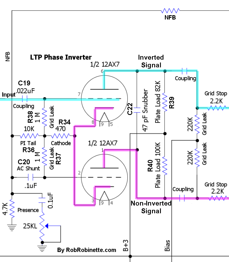
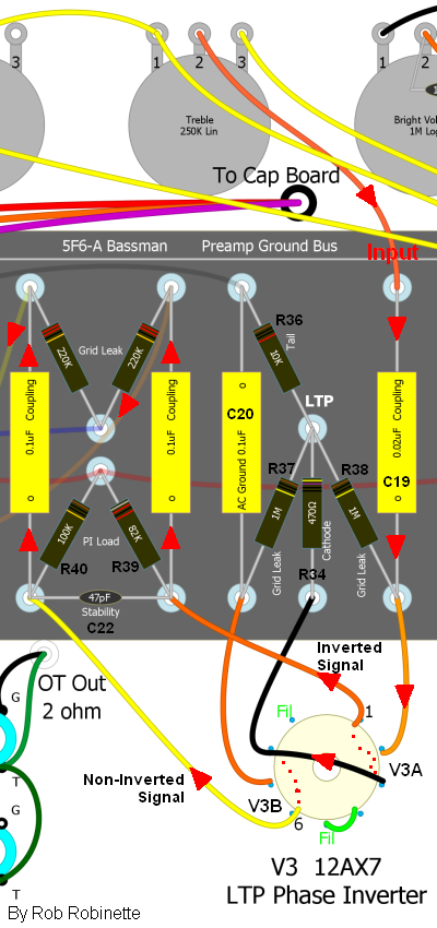
The LTP in the Fender 5F6-A Bassman is identical to the Marshall Plexi, 2204 and JCM800 amps except Marshall adds an additional 4.7k "NFB Tail" resistor in parallel with the presence pot. Signal flow shown with red arrows. Component numbers on the schematic and layout match. The signal enters the phase inverter at V3A's grid and flows out both its plate (inverted signal) and cathode (non-inverted signal). The cathode signal flows to V3B's cathode where it is amplified.
For simplicity I will refer to the upper V3A triode as the "upper triode" and V3B as the "lower."
The upper triode in the schematic above has a dual function. It acts as a normal gain stage by outputting an inverted signal at its plate but also acts like a cathode follower by outputting a non-inverted signal at its cathode.
In the schematic above the AC input signal flows through coupling capacitor C19. Cap C19 blocks the upper triode's 32.5v of DC grid voltage out of the tone stack. The signal then flows onto the upper grid while the lower grid is held at a constant DC voltage and all AC signal is sent to ground through shunt capacitor C20.
The upper and lower cathodes are tied together. All of the lower triode's input signal flows from the upper cathode. With the lower grid held constant, signal voltage fluctuations on the lower cathode alter the electron flow from it to the plate which creates an amplified signal on the lower cathode's plate.
R36 is the tail resistor that creates the relatively high voltage (34v DC in the Bassman) needed for the cathode follower function of the upper cathode. It also supplies a near constant current flow shared between the two cathodes--as current increases through the upper cathode the current decreases through the lower and vice versa.
R34 is a standard bias resistor and creates a 1.5 volt difference between both tubes' grid and cathode. Its 470 ohm value shared between the two cathodes is the equivalent of each triode having a 940 ohm cathode resistor so the phase inverter is biased warm.
R37 and R38 are simply grid leak resistors which leak off DC grid current to maintain a steady DC bias voltage between the grid and cathode.
The plate load resistors R39 and R40 are different values to balance the difference in gain between V3A and V3B.
The negative feedback signal from the output transformer's 2 ohm speaker tap is injected into the LTP phase inverter in two places: the lower grid through C20 and between the R36 tail resistor and presence pot which leads to the cathode. The negative feedback signal on the lower grid counteracts the signal on the upper grid resulting in negative feedback attenuation. Injecting the NFB signal at R36 helps balance the feedback signal between the upper and lower triodes.
The Presence control (R35 and C21) removes a variable amount of high frequency from the negative feedback signal. Reducing negative feedback has the effect of boosting output so reducing the high frequencies in the negative feedback signal boosts high frequency output (C21 shunts the high frequency AC NFB signal voltage to ground). Increasing C21's capacitance value will lower the cutoff frequency and bypass a larger range of frequencies to ground therefore boosting a larger frequency range at the speaker output.
Capacitor C22 suppresses oscillations above audio frequencies between the two triodes' plates to help stabilize the circuit.
LTP and cathodyne phase inverters present a very high impedance to upstream circuits because their grid leak resistors are "bootstrapped" to the phase inverter tail resistor. The input signal on the grid is also present at the top of the tail resistor. This in-phase tail resistor signal reduces signal loss through the grid leak resistor which greatly reduces the load shown to the previous gain stage. Since impedance affects an audio filter's corner frequency we must use a much smaller coupling cap at the phase inverter grid to get the same low frequency roll off. This is why phase inverter input coupling caps are so small. AB763 blackface head cab amps use a 500pF coupling cap and the .022uF cap used by Marshall in their Plexi and JCM800 could easily be reduced to .002uF with no effect on tone but decrease the likelihood of blocking distortion.
Function Detail: When a positive voltage signal arrives at the upper grid the reduction of blocking negative electrons on the grid allows electrons to flow from its cathode, through the grid, to its plate. The electrons flowing onto the plate lowers the plate voltage--this is the inverted and amplified output signal. As electrons leave the upper cathode a positive voltage is created on the cathode (scarcity of electrons = positive voltage) caused by the voltage drop across the cathode resistor R34. This positive signal voltage is also present in the lower cathode because the two cathodes are directly connected. Since the lower grid is held constant at 0 volts AC, any change in its cathode voltage will create a voltage difference between the grid and cathode. This voltage difference changes the flow of electrons from the cathode, through the grid to the plate. As the lower cathode goes positive (scarcity of electrons) fewer electrons will flow from it through the grid to the plate. The reduction of electrons flowing onto the plate raises the plate voltage--this is the non-inverted and amplified output signal.
Bassman 5F6-A LTP Phase Inverter Idle Voltage
Note the voltage difference between the resistor junction of 32.5v and the cathodes at 34v equaling a normal bias for a 12AX7 of 1.5v. The voltage difference between the grids (22 and 23v) and the resistor intersection (32.5v) is measurement error caused by voltage probe circuit loading (if it were real the triodes would be in cutoff). Marshall's schematics show the same error with 24 and 25v shown on the phase inerter grids. Both grid voltages are actually the same as the resistor intersection at 32.5v for a bias voltage of 1.5v.
Here's an online calculator for determining the Balance of Output of the Long Tail Pair Phase Inverter.
Here's an online Long Tail Pair Negative Feedback Calculator .
Tweaking the JCM800 Overdrive Intensity and Tone
It's easy to adjust the JCM800 preamp overdrive and tone by changing the value of a few components. These tweaks apply to the Marshall Master Volume/2104, JCM800, my JCM800 6V6 and JCM800 Micro.
The first Attenuator resistor (located between the Preamp Volume pot and input jack) in front of the second preamp stage can be increased to reduce preamp gain. The 470k Attenuator resistor and 1M volume pot form a voltage divider so increasing the Attenuator resistor will cut gain. Try a 560k or 680k there for less gain. If a 680k doesn't do enough then I recommend adjusting the second Attenuator resistor located just before the 3rd preamp stage at the top of the circuit board.Try a 560k, 680k or even up to 1M to reduce preamp gain.
Increasing gain is more difficult in the JCM800 because the preamp is already pushed near the limit of stability. That's why many factory amps have a stability or "snubber" cap on the V1 tube socket. If you want to try for more gain you should start with a 100pf 600v+ ceramic disc cap across the first preamp stage pins 1 & 3 (plate & cathode) to add some stability.
Reducing the second preamp stage Attenuator resistor from 470k to 330k will add gain. If you alligator clip a 1M resistor in parallel with the 470k you'll get 320k to see if you like the mod. 270k will probably be too much gain but you can give it a try by clipping in a 680k in parallel.
If you need to tame the JCM800 high end you can reduce the value of the first Treble Peaker capacitor located in front of the second gain stage between the Preamp Volume pot and input jack from 470pF to 330pf or 270pF. The Bright cap on the Volume pot can also be reduced but keep in mind that cap only comes into play at lower volumes. Marshall used a .001uF Bright cap so try a 470pF, 330pF or even a 270pF cap.
If you just need to reduce a little ice pick then an Ice Pick cap around the NFB resistor can do that without too much side effect on the overdrive tone. Its value can range from 47pF to 470pF, a higher value will cut more highs. You can alligator clip the cap in temporarily to find what you like.
If you are a very high gain player you can cut some low end by reducing the second Coupling cap (2nd coupling cap from the right on the circuit board) from .022uF to .0022uF. This lower value was used by Marshall in many factory Plexi, Master Volume and JCM800 preamps.
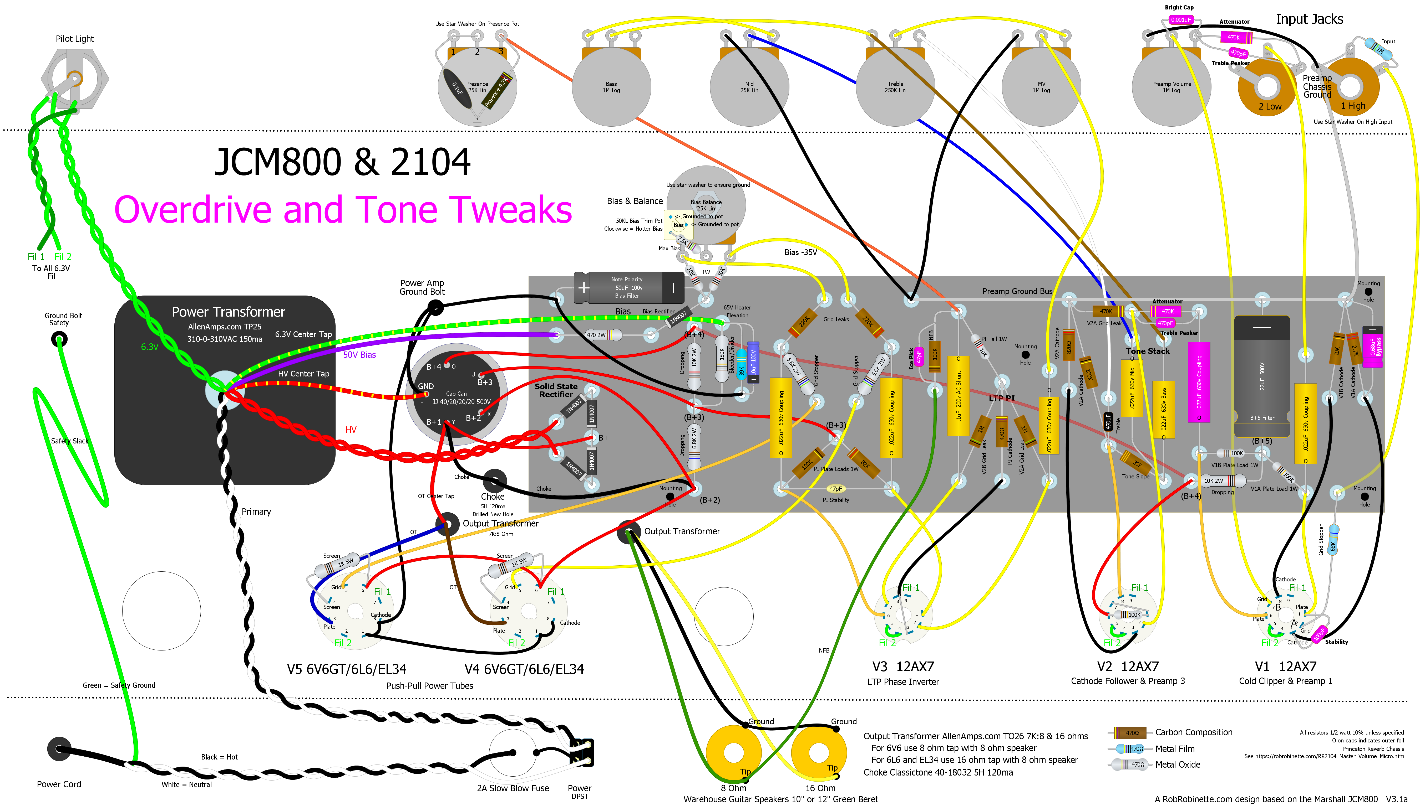
Tweaks in magenta. Click the image for the hi-res version.
Classic Marshall Amp Cheat Sheet
I have a very hard time keeping Marshall amplifier model numbers straight. Marshall model numbers do not have anything to do with the year the amp was introduced. 50 watt amps have two power tubes, 100 watts have four.
JTM45 1962-1966, KT66, 5F6-A Bassman copy
, 45 wattsJTM50
has EL34 and solid state rectifier for 50 watts1959 Super Lead
100W Plexi 1966-1969Channels marked I (bright) & II (normal)
Model 1987 Lead 50W is the 50 watt version
Model 1974 "18 Watt" EL84 introduced 1965
JMP Master Volume Lead amps introduced 1974
2203 Master Volume Lead 100W head
2103 Master Volume Lead 100W 2x12 Combo
2204 Master Volume Lead 50W head
2104 Master Volume Lead 50W 2x12 Combo
EL34 true pentode in England, 6550 beam tetrode in USA
High Sensitivity (bright or lead) and Low Sensitivity (normal) channels
JCM800 Lead Series new name for Master Volume Lead series
Introduced 1981
JCM800 name used after Rose-Morris distribution deal ended
References
RCA Corporation, RCA Receiving Tube Manual, RC30.
Merlin Blencowe, Designing Tube Preamps for Guitar and Bass, 2nd Edition.
Merlin Blencowe, Designing High-Fidelity Tube Preamps
Morgan Jones, Valve Amplifiers, 4th Edition.
Richard Kuehnel, Circuit Analysis of a Legendary Tube Amplifier: The Fender Bassman 5F6-A, 3rd Edition.
Richard Kuehnel, Vacuum Tube Circuit Design: Guitar Amplifier Preamps, 2nd Edition.
Richard Kuehnel, Vacuum Tube Circuit Design: Guitar Amplifier Power Amps
Robert C. Megantz, Design and Construction of Tube Guitar Amplifiers
Neumann & Irving, Guitar Amplifier Overdrive, A Visual Tour It's fairly technical but it's the only book written specifically about guitar amplifier overdrive. It includes many graphs to help make the material easier to understand.
T.E. Rutt, Vacuum Tube Triode Nonlinearity as Part of The Electric Guitar Sound
[ How the 5E3 Deluxe Works ] [ Deluxe Models ] [ DRRI & 68 CDR Mods ] [ Amp Troubleshooting ] [ My 5E3 Build ] [ Spice Analysis ] [ The Trainwreck Pages ] [ Fender Input Jacks ] [ B9A Prototype Boards ]