How To Build a Tube Amplifier
By Rob Robinette
Have comments or corrections? Email rob at: robinette at comcast dot net
For a first amplifier build you should consider a kit because it can be difficult to source all the correct components and shipping charges from multiple vendors can add up. Building a kit is also a great way to boost your understanding of electronic theory and tube amplification. I recommend Mojotone.com and BootHillAmps.com for complete or partial tube amp kits. If you are tight on cash consider building the chassis only and playing through an extension cab (if you don't have an extension cab consider borrowing one). You can always buy a speaker and buy or build a cabinet after you successfully get it up and running.
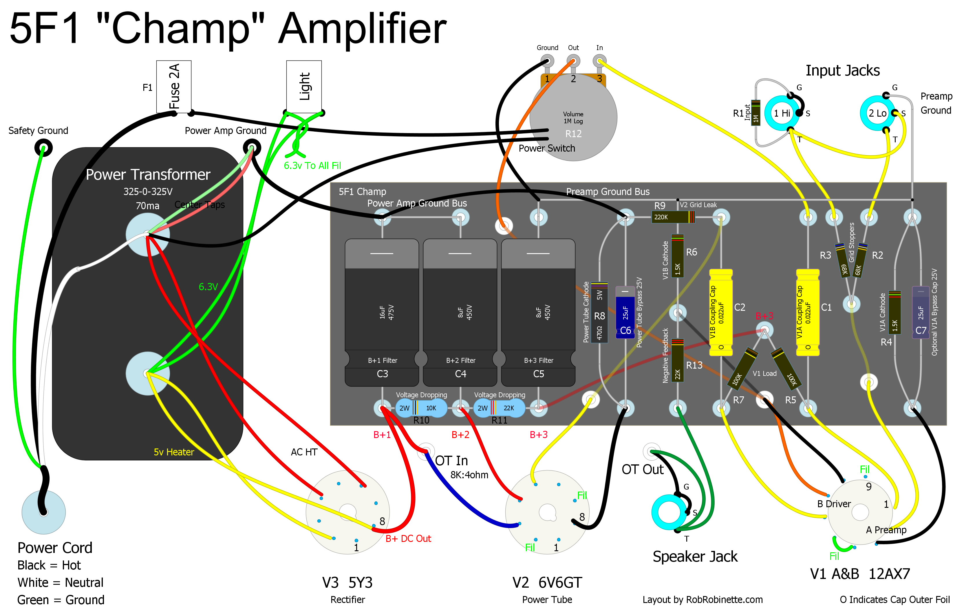
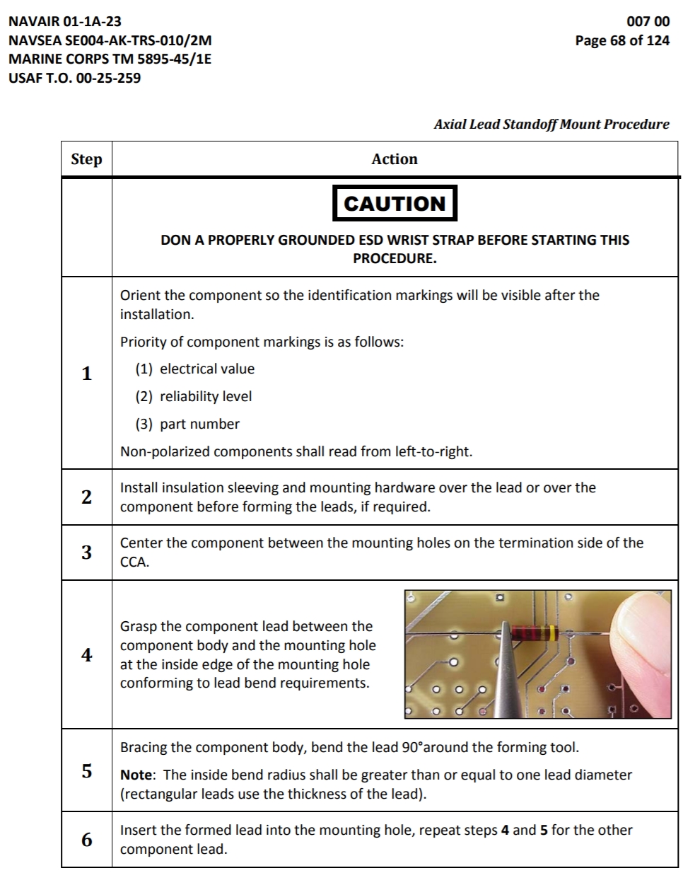
There's no better guitar amp to start with than the Fender 5F1 Champ. It has only 26 components but sounds fantastic. The circuit is so simple I use it in my How Tube Amps Work webpage. It is a single-ended amp with one power tube. Keep this in mind when choosing your first build, anyone can piece together a complex amp. The problem is as complexity increases the more likely you are to make an assembly mistake and troubleshooting a complex amp can be extremely difficult for a beginner. That's why I recommend the simple 5F1 Champ.
5F1 Champ Chassis
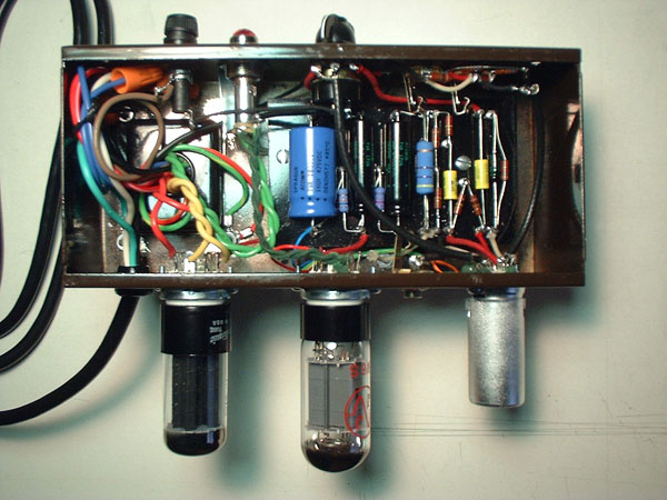
Control on top, Circuit Board inside, tubes on bottom: V1 Preamp Tube on right, V2 Power Tube in center, V3 Rectifier Tube on left. The Power Transformer and Output Transformer are attached to the other side of the chassis.
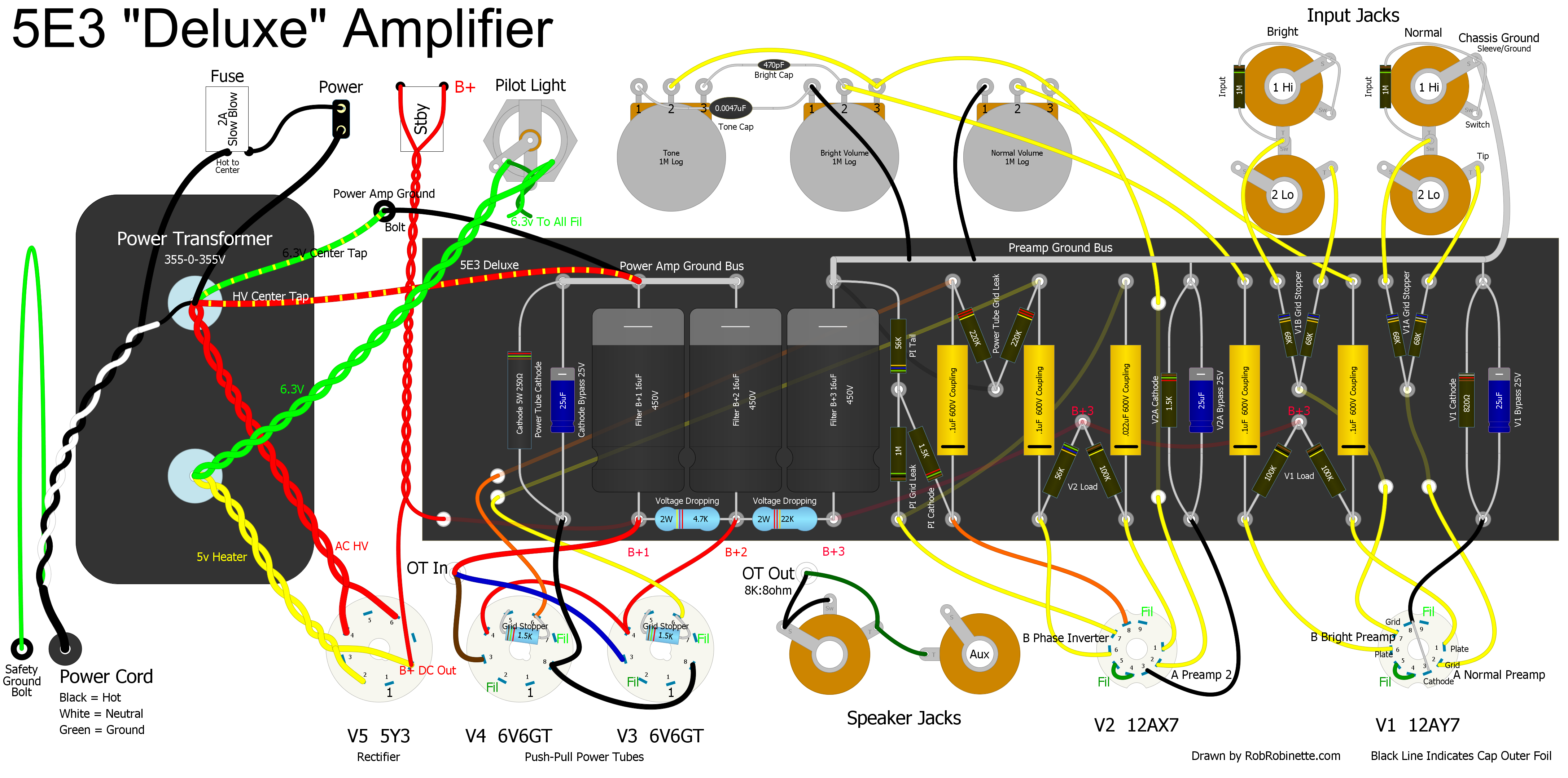
Another option for someone that has some electronic experience is the wonderful Fender 5E3 Deluxe amplifier. It has two power tubes in a push-pull configuration and is loud enough for many gigs.
I went from being a lousy solderer and having a casual knowledge of electronics (I couldn't even calculate the value of 3 parallel resistors) and having no idea how tubes worked to really understanding electronic amplification and tube theory and my soldering skills are now top notch after building an amp or two. Researching that first build motivated my learning and I have really enjoyed the entire process--and then of course there's the end result--having a nice self-built tube guitar amplifier to play through.
Opening a tube amp kit and seeing all those little parts can be overwhelming so I recommend you do an inventory of the big parts like transformers, chassis, switches, tube sockets, etc., then immediately begin assembling the circuit board. Getting all those little resistors and caps in place on the board will make your amp project seem much more manageable and it will help you identify missing components or circuit board layout problems. It sucks to come close to completing an amp and then realize you're short a capacitor and have to wait for delivery.
I also recommend you study factory built examples of the amp you plan to build so you know what your amp should look like. Also go to the tdpri.com DIY Amplifier Forum and look at similar amp builds.
These amp build instructions from StewMac are very good: StewMac_15_Watt_Build_instructions
WARNING: A tube amplifier chassis contains lethal high voltage even when unplugged--sometimes over 700 volts AC and 500 volts DC. If you have not been trained to work with high voltage then have an amp technician service your amp. Never touch the amplifier chassis with one hand while probing with the other hand because a lethal shock can run between your arms through your heart. Use just one hand when working on a powered amp. Learn how to drain the filter capacitors. See more tube amplifier safety info here.
This is the General Amplifier Build Sequence I Recommend
Assemble the circuit board with longer than needed lead wires.
Install the tube sockets and pilot light into the chassis. Match the tube socket pin orientation to your layout diagram.
Install the power transformer into the chassis. Use grommets in the chassis holes where wires pass through.
Wire the heater circuit with regard to heater wire phase.
Install jacks, pots, fuse, power, standby and ground switches and as much of their wiring as possible.
Install the output transformer and choke.
Install the power cord.
Install the circuit board.
Trim the circuit board wires to length and solder their connections.
Do a thorough final inspection before startup.
Complete the Amplifier Startup Procedure.
Build or buy a cabinet.
Mount the speaker into the cab.
Finish the amp, install faceplate, knobs and insert the chassis into the cab.
Create an Amplifier Tube Chart
How to determine the outer foil lead and orient your non-polarized capacitors.
Building an Amplifier
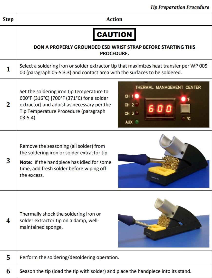
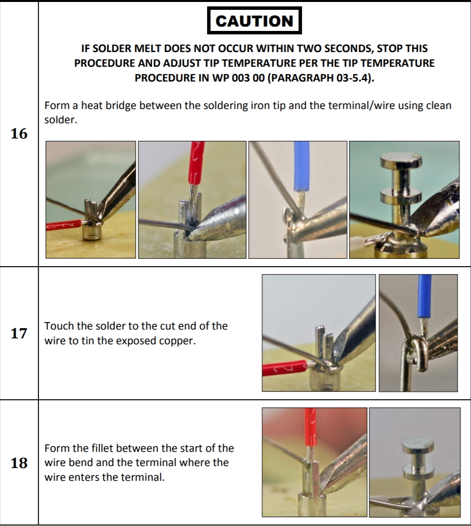
You need a good quality soldering iron with a clean, pre-tinned tip to successfully solder eyelets and turrets. Frequent tip steam cleanings using a damp sponge will make soldering easy and keep your solder joints looking good. For high quality solder joints you must use rosin flux on the eyelet/turret and the component leads because it cleans and removes oxidation so the solder can adhere for a good, long term connection. I just dab a little flux on the joint using a thin artist paint brush or you can use a refillable flux pen. You want good solder joints because chasing a cold solder joint can be a colossal pain in the butt. I'm a fan of the $99 Hakko FX888D soldering iron. Weller soldering irons are also well liked.
I have run into turrets that still have some sort of lubrication on them that can make soldering very difficult. If using flux on a turret doesn't make it easy to solder then you may need to wipe them down with rubbing alcohol to get them clean. When soldering turrets keep in mind they are pretty good heat sinks so you need to use a larger iron tip and preheat the turrets. I use a big fat chisel tip with turrets. Just apply iron heat to the turret for a second or two before making contact with the component leads. You need the keep the iron tip in contact with the turret and all the component leads to get a good, shiny solder joint. This will keep you from frying components as you wait for the turret to get hot enough to bond with the solder. Your iron's tip size & temperature should allow a good joint with 2 seconds or less contact with component leads.
Speaking of frying components, it's a good idea to use heat sink clamps on component leads--especially capacitor leads--to protect the component during soldering. Even just an alligator clip on the component lead between the soldering iron and component body will protect it from over heating. This is a pretty good soldering training video. Part 2 is about soldering turrets.
I like to use 60/40 .031" solder for most amp soldering.
I like to use 22 gauge solid core wire for everything except 20 gauge for heaters but even 22 gauge is adequate for heater wiring. Solid core wire allows for better lead dress because the wire will stay where you put it but some feel it can cause microphonics. I haven't had that problem.
Start your build with the circuit board itself, either eyelet, turret, B9A development board or even perf board. If you are making your own circuit boards I recommend you use #3 Eyelets or Turrets designed for 1/8" (0.125") thick circuit board. Making your own eyelet or turret board is surprisingly easy with the right board making tools. Doug Hoffman sells a variety of tube amp circuit boards using either eyelets or turrets and you can buy them empty or with components soldered in. He also has an online program for creating a circuit board design then he'll make it for you. You can also submit a DIYLC file to Hoffman to create a custom circuit board.
I like to measure and record the resistance value of all resistors just before I place them on the circuit board. I write the measured values on a printed copy of the amp layout diagram. It can be impossible to measure some resistors once they are in circuit and it's a very common mistake to install a 470K resistor instead of the required 470 ohm. Measuring the resistors just before installation can save you from hours of frustrated troubleshooting. Also, knowing the exact resistance value can come in handy when measuring bias and troubleshooting.
Install the components to populate the board but don't start soldering until the components and lead wires are all in place and you're sure they are placed correctly. If you have access to an oscilloscope you can easily determine the outside foil lead and orient your non-polarized capacitors for least noise.
I recommend securing the big filter capacitors so they don't hang by their leads. You can use a mild glue (remember, someone will need to change these out someday) or drill two holes in the circuit board and wrap a tie-wrap around the board and caps. Put the tie-wrap on before soldering the leads to keep from stressing the leads.
Ensure the negative terminals of the big electrolytic filter capacitors are connected to ground because they may explode and damage the output transformer if installed backwards. The exception to this rule are the filter capacitors in a fixed bias circuit. Since the bias circuit is dealing with negative voltage the filter caps are connected with their + terminals to ground. Most filter caps have an 'indention' on their positive end and arrows pointing to the negative end.
You may need to install the circuit board hold-down bolts or standoffs before covering them up with components.
Recommended Resistor & Capacitor Types
I like to use carbon film resistors in classic circuits in place of carbon composition these days because carbon film create much less resistor "hiss" (shot noise). They are a nice compromise between classic carbon composition and ultra quiet metal film resistors. If you want your circuit board to look 1950s and '60s period correct then you will need to use carbon composition resistors. I recommend metal film resistors for the input (V1 grid leak) and V1 grid stopper resistors for minimal resistor hiss injection into the first gain stage. I don't recommend metal film for anything beyond the input stage for classic tube amps because they seem to sound a little too sterile compared to carbon comp and carbon film. Having said that, for the quietest amp you should use metal film everywhere except for the 3 watt and greater power or "voltage dropping" resistors and screen resistors where metal oxide should be used.
I like to use higher watt rating resistors to reduce hiss. Fender used 1/2 watt resistors for plate loads in the '50s and '60s but I recommend 2 watts to reduce resistor temperature and therefore reduce noise. Higher rated resistors will also increase amp longevity.
One of the more difficult aspects of building your first tube amp is figuring out all the different types of capacitors used in them. For capacitors in the signal path of classic amps I like to use Mallory 150 polyester film capacitors (now made by Cornell Dubilier CDE). Another set of popular signal caps are the Sprague 225P series "Orange Drop" polyester film caps which are also now made by CDE. The Mallory 150 and 225P Orange Drop caps are very close in tone and construction to the "mustard" caps made in the 1950s and '60s. Polypropylene signal caps are also an option and tend to be more robust than polyester.
For cathode bypass caps these electrolytics are my favorites. For small, Marshall sized 0.47 and 0.68uF cathode bypass caps I like these Vishay & Kemet 0.47uF tantalum and 0.68uF tantalum caps.
"Axial" capacitors have their leads coming out of both ends of the cap. "Radial" caps have both leads coming out of one end and are designed to be mounted standing up. Classic amps used axial caps.
For pF value caps typically used as bright caps and tone stack treble caps I like to use silver mica caps.
For power supply filter caps I'm a fan of F&T caps. For tremolo circuits I go with what Fender used, ceramic disc caps. I don't like to use ceramic discs in the signal path because they tend to be microphonic due to their large, flat and thin structure.
Component Placement and Soldering
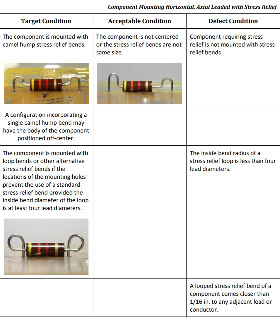
Nice straight component leads look good but they stress the component during expansion and contraction every time the amplifier warms and cools during a power cycle. Adding some bend to your component leads is the way the military and NASA demanded their circuit boards be built.
Mil Spec Turret Board Strain Relief
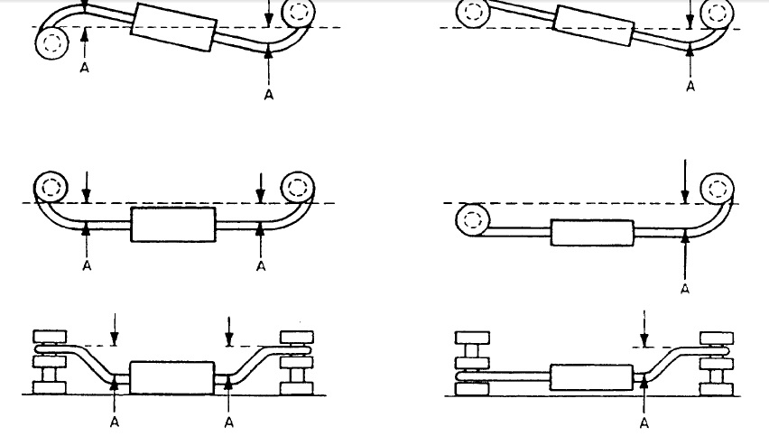
You need some bend in your component leads to allow for expansion and contraction during amplifier heat cycles.
Standoff/Strain Relief Lead Bends
This lead bend adds strain relief and keeps the component above the circuit board.
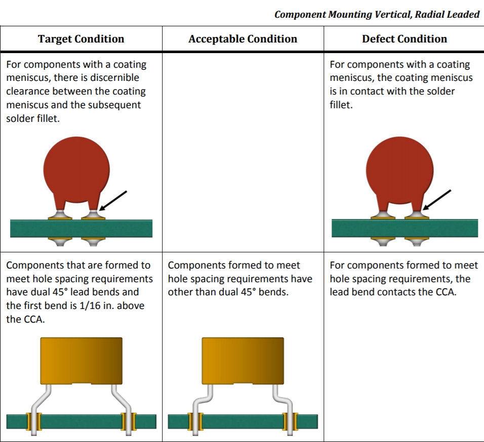
Mounting Radial Caps
Circuit Board Strain Relief
Bend & Trim Leads
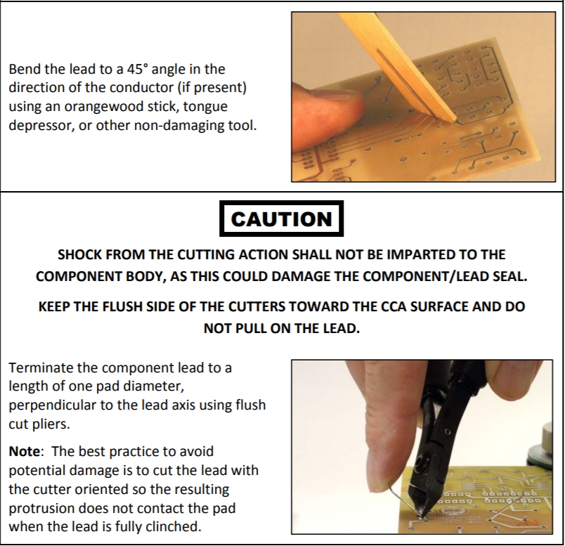
Using a flat wooden stick to bend the leads prevents lead scratching.
From NASA Soldered Electrical Connections
Mounting of Parts to Turret Terminals
1. Parallel Mounting. Parts shall be mounted parallel to, and in contact with, their mounting surface. Slight angularity is permissible. One watt and greater resistors should be mounted above the mounting surface for cooling.
2. Lead Lengths. The length of leads between parts and terminals should be approximately equal at both ends, except when special part shapes require staggering.
3. Stress Relief. Where parts are mounted between turrets it is mandatory to put a stress relief bend in at least one lead (Figure 8-5).
NASA Component Lead Strain Relief
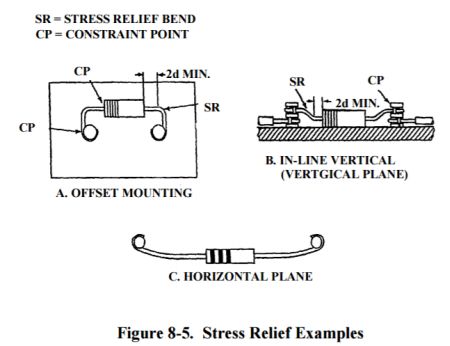
"2d MIN" means a minimum of 2 lead diameters.
If using turrets you can suspend your resistors above the board to aid in cooling but large capacitors should rest against the circuit board. I like to add a dab of silicone RTV (clear silicone caulk) to hold down large filter caps. RTV will hold them in place but it is still easy to remove the caps for replacment. I do not recommend hot glue.
Remember to leave the turret top holes available for wires that run to tubes, controls and jacks. You can connect lead wires to the bottom turret hole for a cleaner look but be sure and use a circuit board bottom cover which will hold leads in place. With no bottom cover your leads may fall out when you solder components to the top of the turret.
The exception to the rule above is for components you know will have to be replaced in the future, like electrolytic filter capacitors, put their leads in the turret top hole to make unsoldering them easier. If you think you may mod your amp then place components you think you may swap out with their leads in the top turret holes to make replacement easier.
To attach component leads to turrets I use the "1/2 to 3/4 wrap around the turret" method which is old mil spec. Leave about 1/4 inch lead sticking out from the wrap so you can grab the lead with a pair of needle nose pliers to facilitate removal for a future repair.
22 or 24 gauge wire is fine for all the amp's wiring except maybe the heater wires. For heater wires even 22 gauge is plenty big but many people like to use 20 or 18 gauge but the thicker wire, the more difficult it is to fit it in the little tube socket pin holes. I typically use 20 gauge green and black wires for the heaters so I can keep track of heater phase.
For wire color I like to use yellow for the signal path, red for power, black for ground and cathodes. If two signal wires are next to one another I sometimes use orange wire to differentiate them. I like to use green and black wires for heaters so I can keep track of heater phase.
If you put shrink-tubing over a resistor I recommend you double the resistor watt rating because the shrink-tube will insulate the resistor and make it more difficult to shed heat.
With the circuit board fully populated but not soldered it's a good time to post pics of the circuit board (front and back) on a guitar amp forum for others to review. I like the TDPRI Shock Brothers DIY Amps forum (I'm robrob). Be sure and take a photo of the back side of the board so you can review it in case you have to troubleshoot the amp at startup--you don't want to have to remove the circuit board to verify its backside wiring and solder joints.
Once you are sure your board is right insert the wire leads that run from the board to the tube sockets and pots with a couple of extra inches of length and solder everything together. When you're finished take a very close look at every solder joint--it's common for people to miss a joint or two and leave them unsoldered. If you have some dull or nasty looking joints use a solder sucker or solder wick to remove the solder. Put some flux on the joint and leads and re-solder the joint. Remove flux using 90% isopropyl alcohol.
Soldering Iron Tip Prep
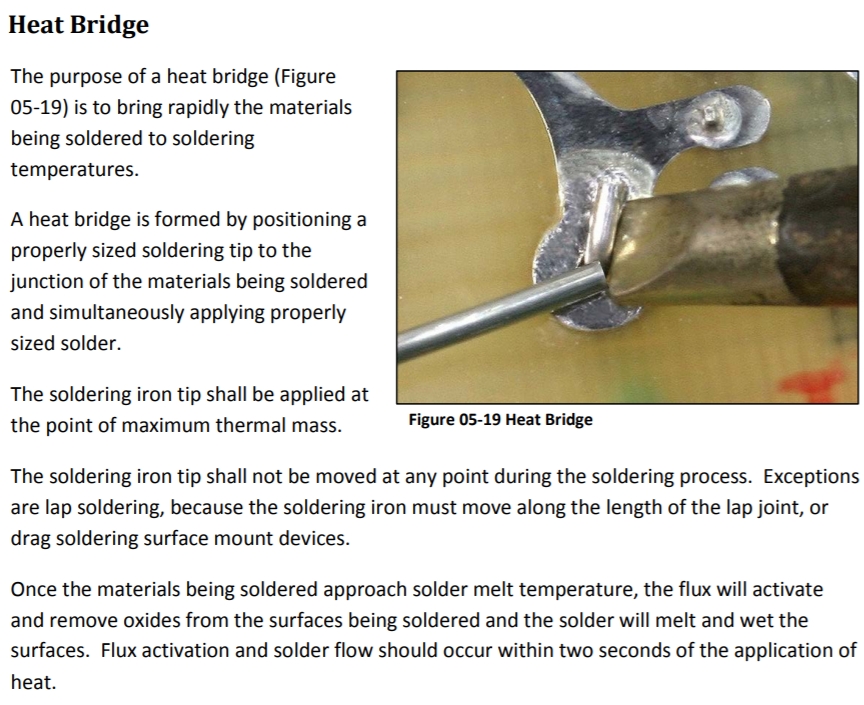
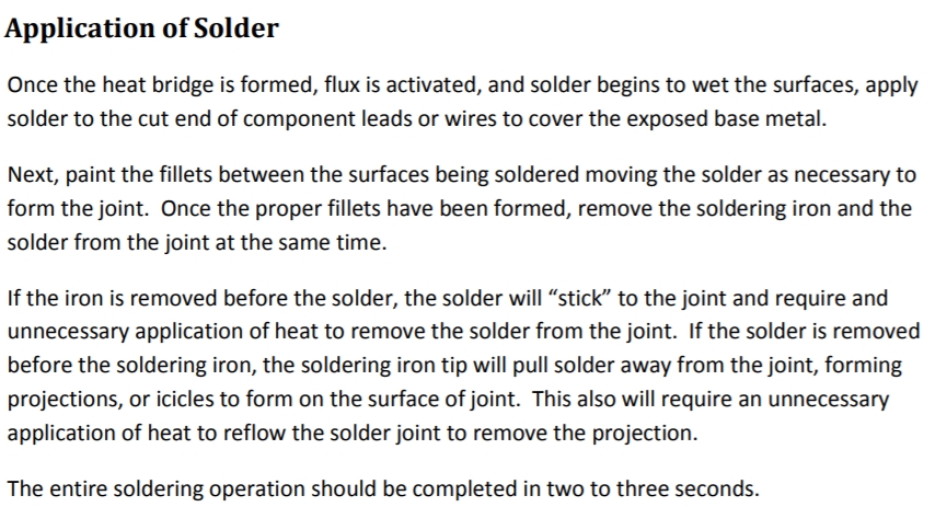
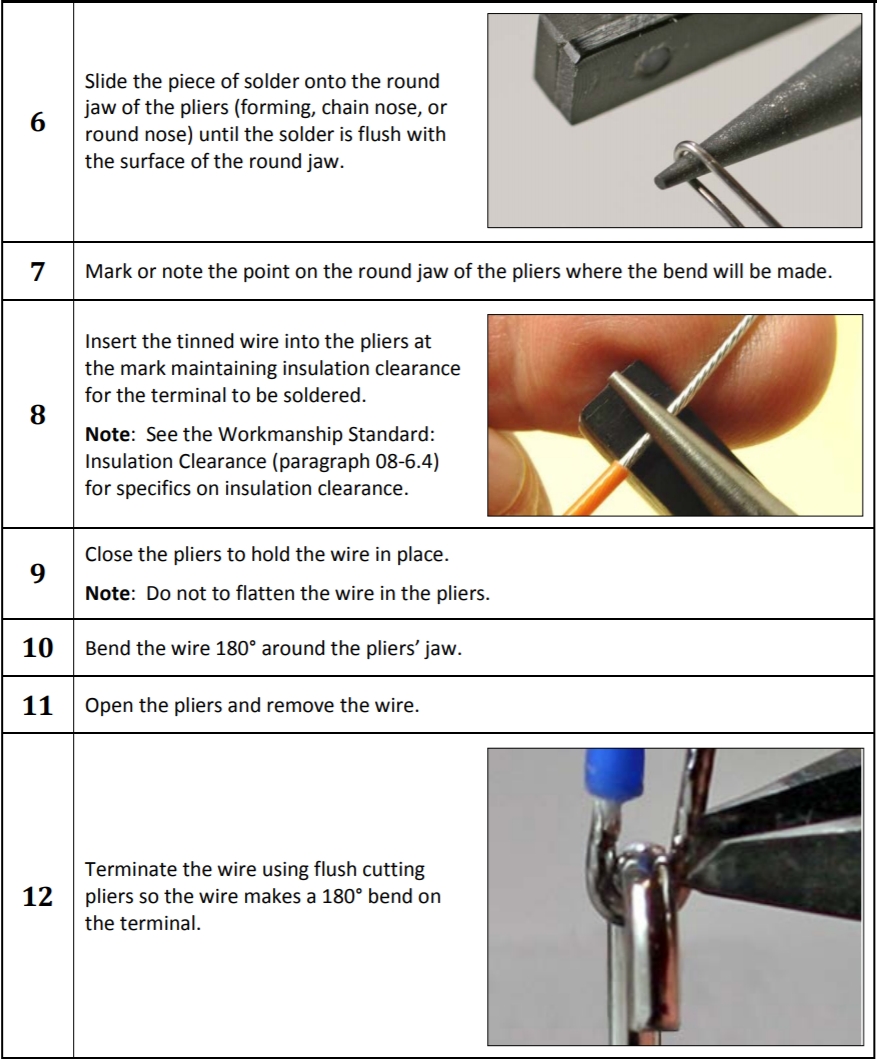
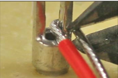
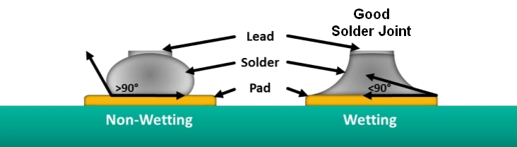
How To Solder
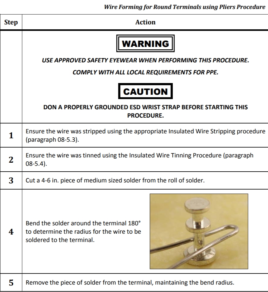
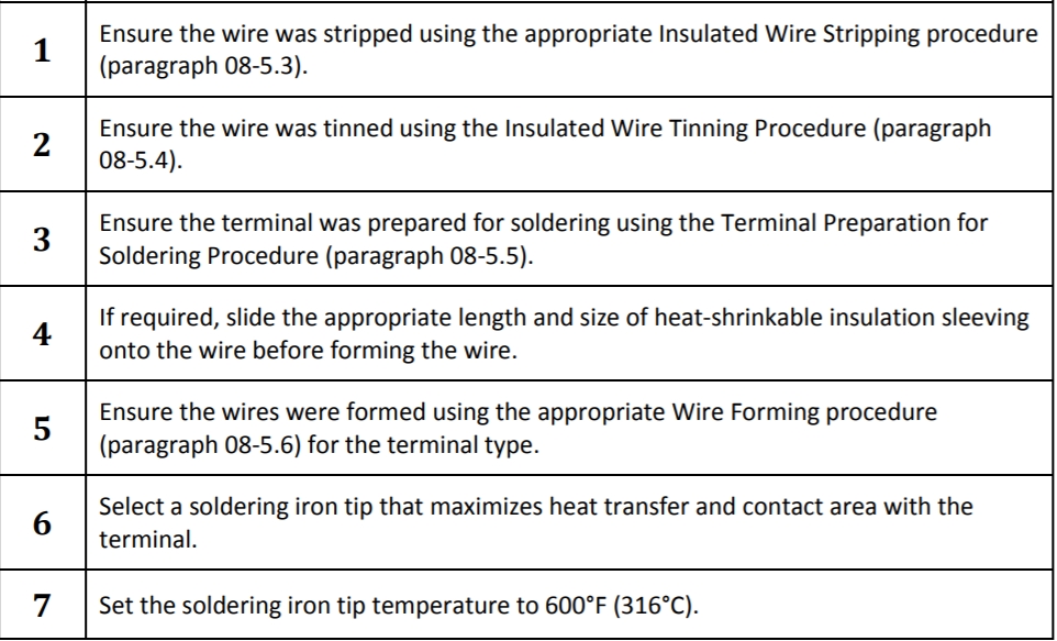
Wiring Turrets
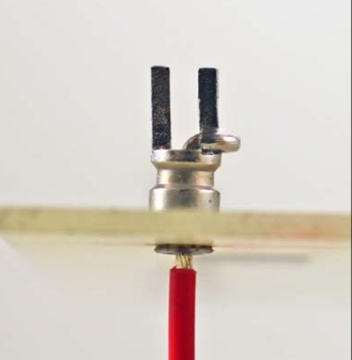
Bifurcated (Dual Post) Terminals
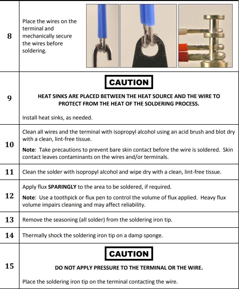
Soldering Turrets
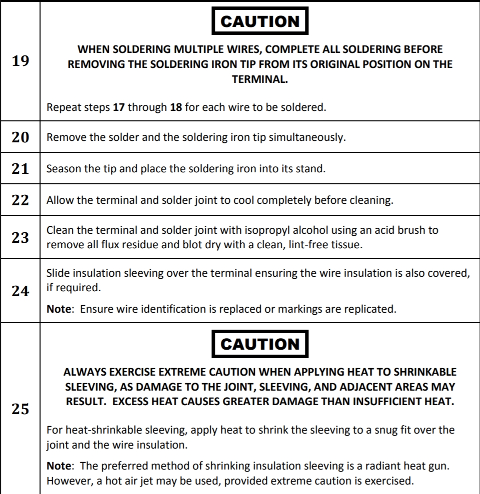
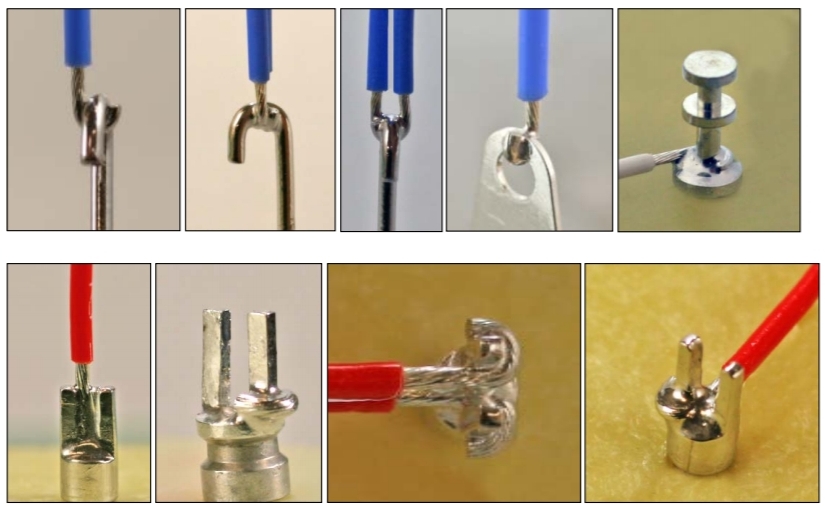
Turret Bottom Entry
Good & Bad Circuit Board Joints
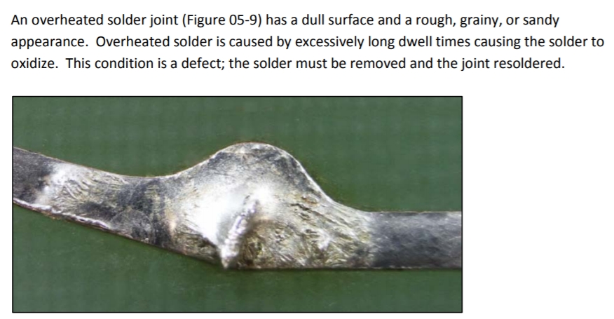
Overheated Solder Joint
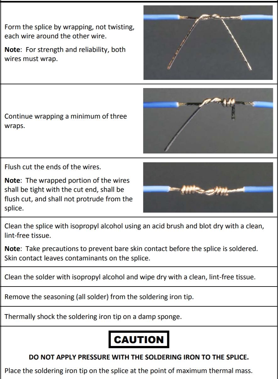
Mil-Spec Wire Splice
Connecting the power transformer high voltage center tap directly to the first filter cap negative terminal can reduce hum and buzz by minimizing pulsing 120Hz ground return current.
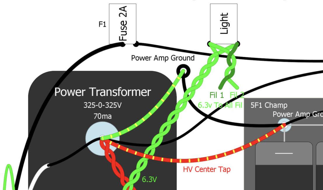
Connecting the (red/yellow) high voltage center tap on the first filter cap negative terminal can reduce 120Hz hum and buzz.
If you make your own chassis I recommend using a step drill bit to drill the tube socket, jack and pot holes.
Mount the power and output transformers to the chassis. Do not twist the output transformer wires, especially the primary wires that run to the power tube sockets. Twisting them together can allow capacitive coupling and the loss of high frequencies.
Mount the tube sockets and pilot light in the chassis and wire the heater circuit before installing the circuit board. If you plan to do Fender blackface style flying heater wires then save the heater wiring for last. I recommend you connect the 6.3V filament heater wires from the power transformer directly to the first power tube, then split two wires from there: a thin set of wires to the pilot light and one to the next tube. Try to keep the tightly twisted heater wires down against the chassis floor to reduce noise and hum (unless you're using flying heater wires) and keep track of phase.
Install pots, fuse, power & standby switches, transformers and choke in the chassis and do as much wiring on these as you can before you mount the circuit board because it can get crowded in the chassis, especially Fender tweed chassis. It's a good idea to use washers on your output transformer and choke bolts to reinforce their mounting flanges. Their weight can cause their mount holes to rip if the amp is dropped. Don't forget to do the heater wires before you install the circuit board (unless doing flying heaters).
Install the power cord. The black hot wire usually connects to the fuse's center terminal. The white neutral wire connects to a power transformer primary wire. The green safety ground wire is bolted directly to the chassis using a star washer for a good electrical and mechanical connection. The safety ground wire needs to have more slack in it than the other power cord wires so if the cord is yanked out of the chassis the ground wire is the last to come loose.
USA Power Cord Wiring
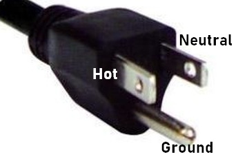
Modern U.S. wall cords and sockets have a narrow blade for Hot (black wire 120v), a wide blade for Neutral (white wire ground), and a round or 'D' shaped prong for the chassis Safety Ground. Power cord wire colors are sometimes non-standard so use a multimeter in continuity mode to identify the Hot, Neutral and Ground wires.
Bolt the circuit board into the chassis but make sure you have the transformers and choke installed and bolted down before the circuit board covers them up. 1950's and '60's Fender amps used an insulation board to go between the circuit board and chassis. The two layers were screwed to the chassis using sheet metal screws. I'm not a fan of that technique so I like to use standoffs to get the circuit board up off the chassis by a 1/4 inch or so.
Trim all the circuit board lead wires to length and solder them to the tube sockets and pots. You don't want the leads too short because you need to push them down to hug the floor of the chassis. You also may have to move them around for proper lead dress--lead separation and crossing them at 90 degrees when possible.
Pay particular attention to your preamp tube plate and grid wires. Keep them separated because they can interact with one another and cause hum and oscillation.
If you are doing flying heater wires install them last.
If your amp has adjustable bias set the bias pot for max resistance for a cold, safe bias.
Safety Ground
Before adding power to a new amp be sure and verify the safety ground connection. Plug a guitar cable into an input jack and check that you have continuity (meter "beep") between the guitar cable's sleeve (the part that isn't the tip) and the amp's power cord ground prong. In the USA it looks like this:
Verify you have continuity between the amp's power cord ground prong and guitar cable and speaker cable sleeve.
If your amp has a main speaker jack, plug a cable in and test again for continuity between the cable sleeve and power cord ground prong. If your amp has speaker wires one of them should show continuity with the power cord ground prong.
You must not power up the amp until you have safety ground continuity between the power cord ground prong, guitar cable sleeve, speaker cable sleeve and chassis because the amp is a deadly shock hazard without it. If you don't have continuity use your meter's continuity function to verify your power cord wiring: Hot to the fuse, Neutral to the power transformer primary and the ground prong wire bolted directly to the chassis.
Cap & Diode Polarity
Also before adding power be sure and verify the filter caps are connected - to ground. If your amp has a fixed bias circuit make sure its bias filter cap(s) are connected + to ground because they deal with negative voltage. Getting any of this wrong can lead to exploding capacitors and damaged transformers.
Capacitor Polarity
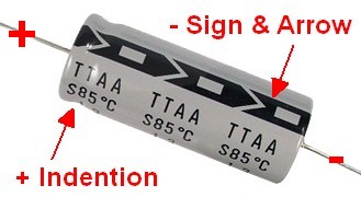
Note the cap's case indentation on the + end of the cap and the arrow pointing to the - end.
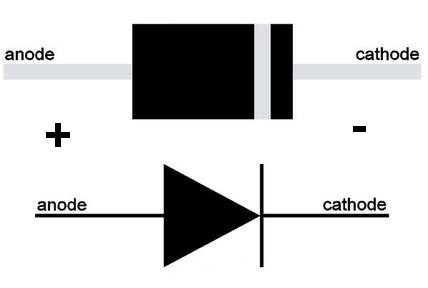
If your amp has any diodes installed, such as a solid state rectifier or fixed bias circuit, make sure their polarity is correct--the striped end of the diode is the cathode.
Solid State Diode Polarity
Post detailed pics for forum review before applying power.
Don't insert the tubes until you power it up without tubes to check the power transformer output voltages. I recommend you follow my Amp Startup Procedure. Following it can prevent damage from a miss-wired amp.
If you have a light bulb current limiter you should use it for the startup.
CAUTION: You must connect a speaker anytime you power up the amp with the power tubes installed to prevent output transformer and power amp damage.
After startup remove the light bulb limiter and measure and set the bias. If your amp is cathode biased and the bias is measured above about 110% max dissipation you can install a larger value power tube cathode resistor to cool the bias.
Play the amp and sample the clean and overdrive tone. Try it with your usual pedals to make sure it behaves with no oscillation squeals or blocking distortion.
The two most common assembly mistakes are mis-wired input and speaker jacks. If your amp doesn't make guitar sounds at startup check those first.
If your amp has problems see the Tube Amp Troubleshooting Guide.
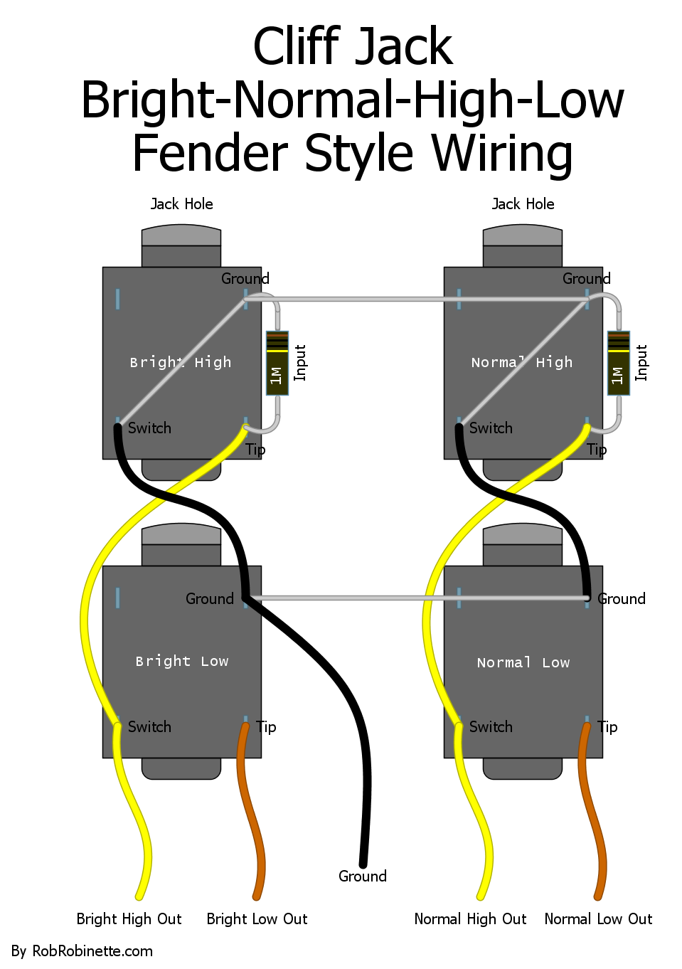
Cliff jacks are isolated from the chassis and must be grounded via a ground wire. View is from the rear with jack holes forward.
Heater Wiring Phase
Using the proper heater wiring phase between tube sockets can help minimize 60Hz heater hum. I usually use two wire colors for the heater circuit so I can keep track of heater phase. Heater phase doesn't matter for the pilot light.
Heater phase for preamp tubes isn't critical but I do wire them in-phase. Since the guitar signal phase is inverted with each preamp gain stage keeping the heaters in phase will help 60Hz heater hum self cancel. For in-phase wiring you would run one heater wire from pin 9 of one preamp tube to pin 9 of the next tube.
Power tubes wired in push-pull should also be wired in-phase to take advantage of common mode noise rejection inherent in the push-pull circuit. To wire in-phase one heater wire would be connected to pin 2 on one power tube and pin 2 on the other power tube.
Power tubes wired in parallel should have their heaters wired out-of-phase for hum reduction. We do this because if the same heater hum gets into two parallel tubes the hum is additive--it gets louder. If we wire them out of phase the hum will be subtractive and cancel out. To wire out-of-phase one heater wire would be connected to pin 2 on one power tube and pin 7 on the other power tube.
In amps with four power tubes (two pairs of parallel tubes in push-pull), we want the tubes in parallel wired out-of-phase but the connection between the two parallel pairs should be in-phase. For the Twin Reverb the power tubes are numbered 7, 8, 9, 10 from right to left (as shown below in the layout).
Tubes 9 & 10 are paralleled and make up one half of the push-pull circuit. Tubes 7 & 8 are paralleled and make up the other half of the push-pull circuit.
We want tubes 7 & 8 wired out-of-phase because they are in parallel.
Tubes 9 & 10 are also in parallel so they are wired out-of-phase.
But we need tubes 8 & 9 wired in-phase because they are in push-pull.

V9 and V10 run in parallel so we wire their heaters out of phase. Same goes for V7 and V8 but the connection between V8 and V9 must be in phase to take advantage of push-pull common mode noise reduction.
For stereo single-ended amps (one power tube per channel) you should wire the two power tubes out of phase so any heater hum out of the speakers will cancel.
For stereo push-pull amps each push-pull pair should be wired in phase but the heater phase between the two stereo channels should be out of phase. Again, we do this so that any heater hum that makes it out of the speakers will cancel.
Create a Voltage Chart
Measure and record the following amp voltages for troubleshooting and future reference:
Wall Voltage AC because it affects all the amp's voltages
Power Transformer Output in volts AC
Heater Voltage should be between 5.7 to 6.9 volts AC, see this to lower the heater voltage.
Rectifier Heater Voltage should be between 4.5 and 5.5 volts AC.
These are the only AC measurements, everything below is DC
B+1 Measured at the first filter cap
B+2 Measured at the second filter cap
B+3 Measured at the third filter cap
B+4 Measured at the fourth filter cap (if applicable)
All the tube pin voltages
Finish the Amp
Install the faceplate, knobs, etc. Put the speaker in the cab, wire the speaker, then insert the chassis into the cab.
This is who I use for logo nameplates: https://www.etsy.com/shop/AwardsEtc
Etsy Awards Shop Logo Plate
![]()
Precision Design does a great job creating custom amp faceplates.
Don't forget to connect the speaker--you can damage a tube amp if you power it up with no speaker connected.
I'm not a woodworker so I typically source my cabs from margili.com or Mojotone.com.
Parts and Kit Suppliers
I'm a big fan of Mojotone.com and BootHillAmps.com's amp kits.
If you just need an amp's small parts (no transformers, chassis, cab or speakers), Mojotone sells small parts kits at a great price with quality components. It keeps you from having to source all these parts from multiple suppliers and prevents you from ordering the wrong freakin' capacitors.
For generic parts in large quantities I like Mouser.com.
I also really like TubeDepot.com for tube amp parts, tubes and hard to find tube amp specific stuff. They label and separate their parts so you don't receive one big bag of 1000 mixed parts. Their shipping rates are really cheap too.
Doug Hoffman is also one of my go-to sites for tube amp parts. He also has pre-made amp circuit boards and he'll do custom boards too.
Doug Hoffman and TubeDepot both ship very quickly.
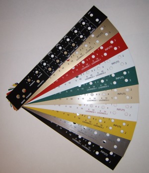
Create an Amplifier Tube Chart
This is a reproduction of a standard tweed era tube chart that Fender glued to the inside of their amps:
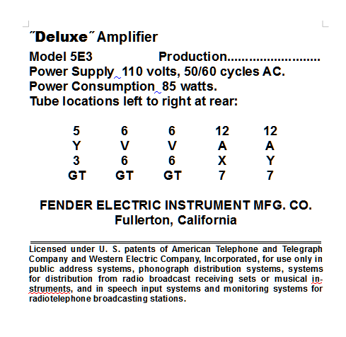
Click the image to download the editable 5E3_Tube_Chart.doc
Here's a good "glue paper to wood" how-to.
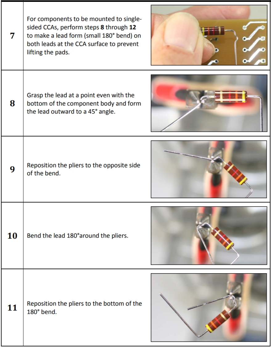
Capacitor Outer Foil
Placing your non-polarized capacitors with their outer foil connected to ground or the circuit's lowest impedance can reduce the amount of RFI (radio frequency interference) they pick up and prevent capacitive coupling between components and nearby wires. Doing this will use the outer foil as a grounded shield. If you have an oscilloscope it takes just a few seconds to determine which lead is the outer foil on non-polarized caps (caps with no + or - end markings). Some caps come marked with the supposed outer foil end but many times the marking is wrong so I recommend testing all your caps before installation. Doing this really can reduce RFI, environmental noise such as LED lights and reduce capacitive coupling in an amplifier circuit.
What does, "connect the cap's outer foil lead to the lowest impedance mean?" The key to getting this right is to realize that to an AC signal, including noise, the DC power supply looks like a "ground". For example let's look at a standard coupling cap in the schematic below. It has a 100k plate load resistor connected to the DC power supply on one end and a 1 megaohm grid leak resistor connected to ground on the other end. The 100k to the power supply is a lower impedance than the 1 megaohm to ground so the cap's outer foil lead should be connected to the 100k plate load resistor. This will allow noise that hits the outer foil to flow easily to and "AC ground".
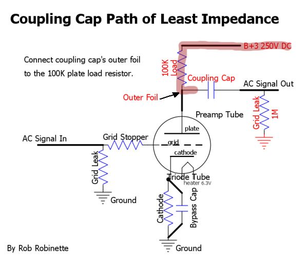
The coupling cap has 100k of impedance to the DC power supply and 1M of impedance to ground. The 100k to the DC power supply is the lower impedance and should have the cap's outer foil connected to it.
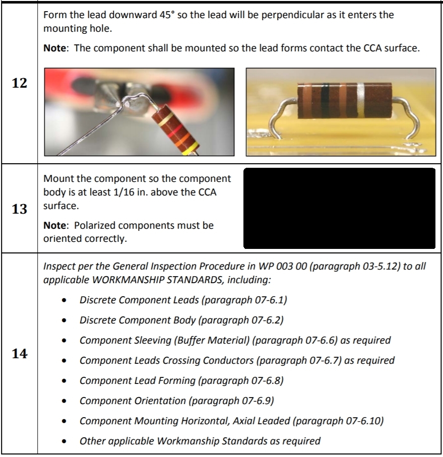
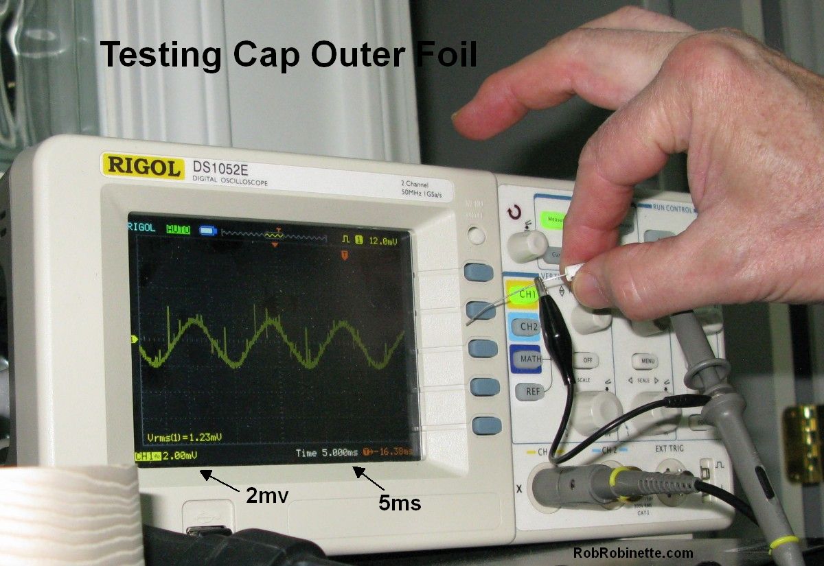
Determine a Cap's Outer Foil Lead Using an Oscilloscope
Set the oscilloscope to its lowest millivolt setting (usually 2 to 5 millivolts) and 5 milliseconds
Clip the oscilloscope probe to one capacitor lead and the probe's ground clip to the other.
Hold the cap between your fingers making sure not to touch either lead. Your body acts as an antenna to pick up RFI noise which is transmitted through your fingers to the cap.
Look at the scope and note the size of the waveform. The waveform is the noise transferred from your fingers into the cap.
Reverse the probe connections and repeat.
When the scope probe ground clip is connected to the outer foil lead the waveform size will be smallest. The smaller waveform represents less RFI noise getting into the cap--and this is a good thing.
Mark the ground probe end of the cap and connect it to the lowest impedance in the amp circuit. In most of this website's layout drawings I have an "o" marking the outer foil end of non-polarized caps.
Cap Hooked Up Backwards
Larger waveform so black ground alligator clip is on wrong (inner foil) lead.
Cap Hooked Up Right
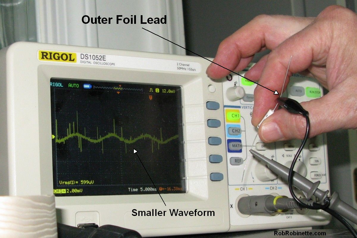
Smaller waveform so ground clip is on outer foil lead. Mark that end of the cap. The oscilloscope is set to 2 millivolts and 5 milliseconds.
Cap Outer Foil Low Impedance Orientation
Note the "O" on the yellow coupling caps at mid right on the circuit board. That is the outer foil lead mark. Connect the outer foil lead to the lowest impedance which is usually the tube plate or ground connection. Most of the layouts on this website have cap outer foil markings like this 5E3 Deluxe layout.
Simple Blackface Amp Design
I designed the RR763 BLACKVIBE amp (see layout and schematic below) for builders who don't want to deal with the complexity of the AB763 circuit's reverb, tremolo and dual channels but still want its authentic tone.
Removing the reverb, tremolo and Vibrato Channel drops the preamp tube count to only two but the tone stays 100% Normal Channel Vibroverb. This amp uses authentic Vibroverb power and output transformers and choke so voltage levels and power output are all Vibroverb. I have listed the recommended Classictone transformers and choke on the schematic and layout below. The filter caps were moved from the doghouse to the circuit board for build simplicity.
Simple Blackface
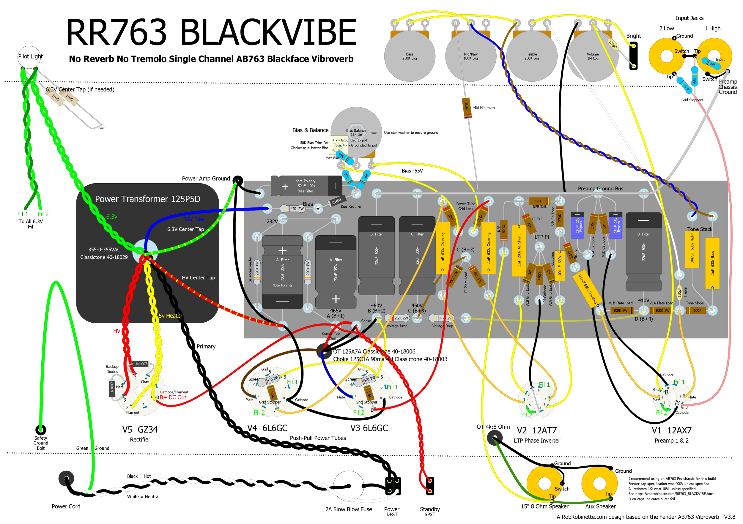
No reverb, no tremolo, single channel AB763 Vibroverb. It's a very simple amp compared to the Vibroverb above. Download the BLACKVIBE pdf here and the DIYLC file here.
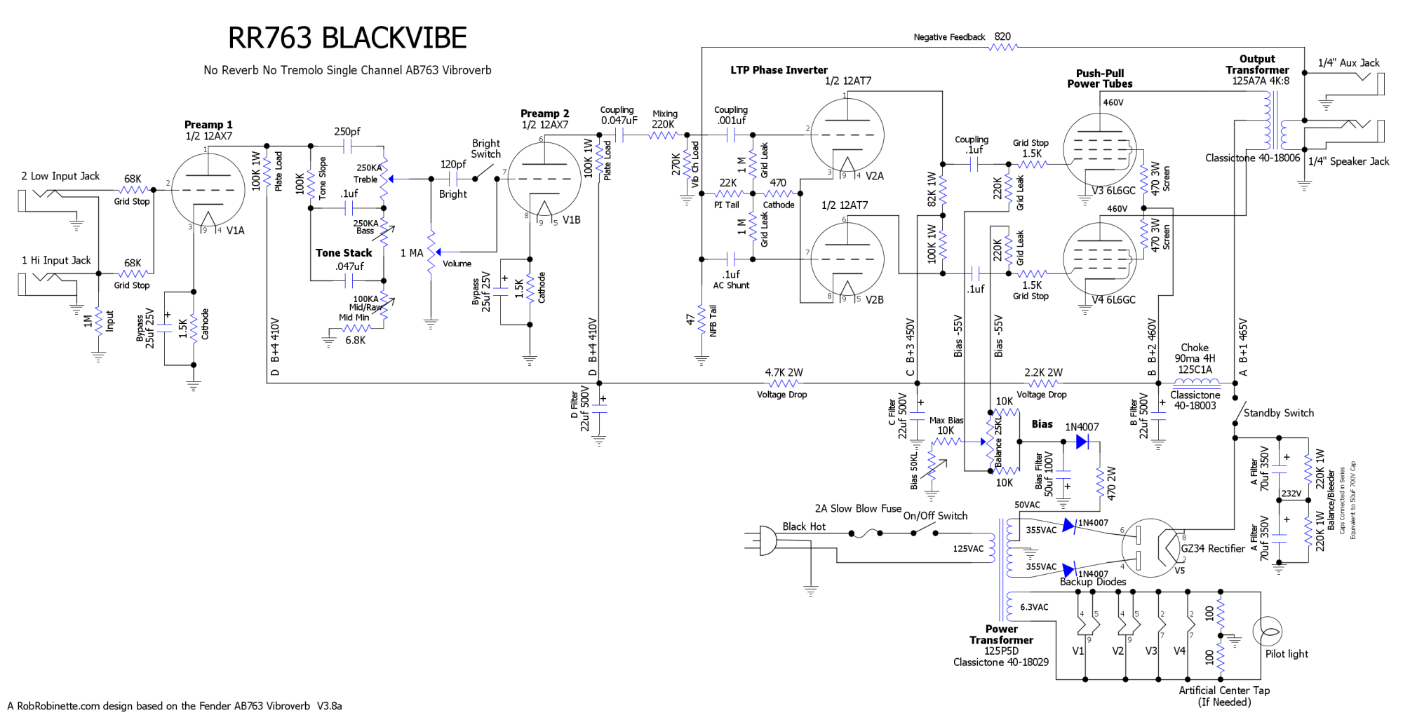
It's very much a single channel Vibroverb. Download the pdf here and the DIYLC file here.
See this for more info on the BLACKVIBE.
By Rob Robinette
References
RCA Corporation, RCA Receiving Tube Manual, RC30.
Merlin Blencowe, Designing Tube Preamps for Guitar and Bass, 2nd Edition.
Merlin Blencowe, Designing High-Fidelity Tube Preamps
Morgan Jones, Valve Amplifiers, 4th Edition.
Richard Kuehnel, Circuit Analysis of a Legendary Tube Amplifier: The Fender Bassman 5F6-A, 3rd Edition.
Richard Kuehnel, Vacuum Tube Circuit Design: Guitar Amplifier Preamps, 2nd Edition.
Richard Kuehnel, Vacuum Tube Circuit Design: Guitar Amplifier Power Amps
Robert C. Megantz, Design and Construction of Tube Guitar Amplifiers
Neumann & Irving, Guitar Amplifier Overdrive, A Visual Tour It's fairly technical but it's the only book written specifically about guitar amplifier overdrive. It includes many graphs to help make the material easier to understand.
T.E. Rutt, Vacuum Tube Triode Nonlinearity as Part of The Electric Guitar Sound
[ How the 5E3 Deluxe Works ] [ Deluxe Models ] [ My 5E3 Build ] [ The Trainwreck Pages ] [ Fender Input Jacks ] [ B9A Prototype Boards ]