Amateur Radio Hotspot VHF & UHF Digital Modes
By Rob Robinette K9OJ
I use a few Chinese MMDVM_HS_HAT_DUPLEX pi hat + pi3 for all my digital ham radio needs. They can do everything Pi-Star/WPSD can dish out including Yaesu System Fusion (YSF), DMR, D-STAR, P25, NXDN, M17, POCSAG paging, YSF-to-DMR, YSF-to-NXDN and YSF-to-P25.
I get my generic Chinese MMDVM_HS_HAT_DUPLEX pi hat from aliexpress.com and it typically takes about three weeks for delivery. I paired them with $35 Raspberry Pi 3s and 4s. The duplex HATs work great and it's what I currently recommend everyone get. It has dual radios with dual antennas for simultaneous UHF transmit and receive.
I had a heck of a time getting my digital radios to communicate with my hotspots so I created this webpage to hopefully help new hotspot users get up-and-running easier and quicker than I did.
If you want to get your feet wet in digital Ham radio before buying an expensive radio you can use Droid-Star (computer and phone based) free software to monitor and transmit on P25, DMR, D-STAR, YSF and others including the exciting new M17 digital protocol.
Jumbo Spot RTQ $40 Hotspot
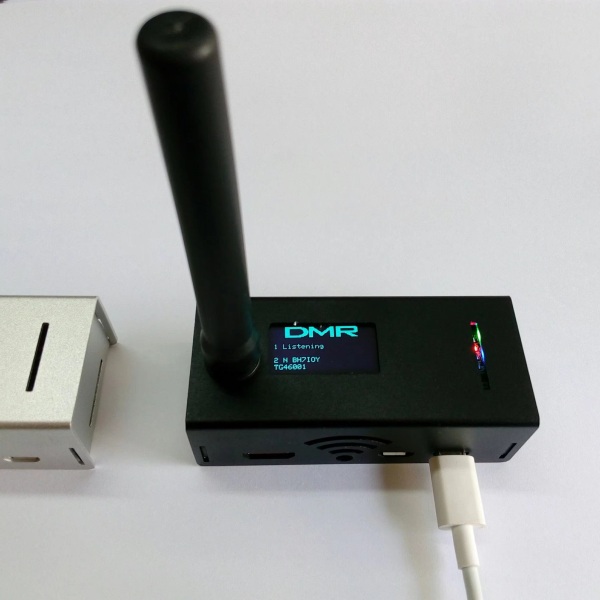
The Jumbo Spot RTQ have Wi-Fi, a single 70cm radio, OLED screen and supports Pi-Star/WPSD, YSF, D-STAR, DMR, P25, NXDN, M17, POCSAG, YSF-to-NXDN, YSF-to-P25 and YSF-to-DMR. The Jumbo Spot transmitter is rated at 20 milliwatts. See my Jumbo Spot Pi-Star settings.
Generic Chinese MMDVM_HS_HAT_Duplex Pi Hat Hotspot/Repeater $38
Dual radios allow simultaneous reception and transmission (duplex operation). I paired it with an old $35 raspberry pi3 with WPSD. Its dual radio chips are rated at 20 milliwatts each. See my MMDVM_HS_HAT_Duplex Pi-Star settings.
Setting Up The Radios
For me setting up the radios to work with a hotspot was much more difficult than setting up the hotspot and Pi-Star software. Here's a rundown on what I had to do to get each radio setup:
For general troubleshooting I recommend you monitor your radio and hotspot transmissions on an SDR or analog radio so you can verify the hotspot is transmitting and your radio is transmitting in digital mode. You can also use the SDR to monitor your radio and hotspot to compare their exact frequency. This can help you quickly dial in the correct Pi-Star/WPSD RX and TX Offset.
The typical "CQ" call for all these digital modes is simply, "K9OJ is listening on talk group 3147".
YSF Yaesu System Fusion FT1DR
D-STAR Kenwood TH-D74
DMR Tytera MD-380
P25 Motorola XTS3000 Model II UHF
M17 Moded Tytera MD-UV380G with OpenRTX
Using Digirig for M17 Transmit and Reception
POCSAG Paging Mode
Decoding POCSAG Messages Using An SDR
DroidStar Software Based Ham Digital Transmission and Reception
Pi-Star Settings
MMDVM_HS_HAT_DUPLEX Pi-Star Settings
Hotspot Info
Upgrade Nano-Spot MMDVM_HS Firmware
What YSF, D-STAR, DMR and P25 look and sound like on a waterfall display
Adding An OLED Display To A Hotspot
Adding A Nextion Display To A Hotspot
Motorola P25 Radio Info
Modifying Motorola CPS Programming Software For Out-of-Band Frequencies
Motorola XTS2500 & XTS5000 Info
YSF
Yaesu System Fusion C4FM is super simple. Just program your hotspot transmit and receive frequencies into a memory and hit the "Dx" button until "DN" (digital narrow) is displayed and you're all set. Pi-Star now supports YSF-to-DMR, YSF-to-NXDN and YSF-to-P25 so you can access these modes with one Yaesu C4FM radio. You can also change YSF "rooms" using DTMF tones. One of the nice things about YSF is it runs on Yaesu radios. They are my favorite amateur radio manufacturer. I have an FT-1DR, FT-70DR, old FT-50 and a new FTM-200DR dual band mobile. All of these radios except the old FT-50 support YSF.
Yaesu FT1DR Hotspot Programming
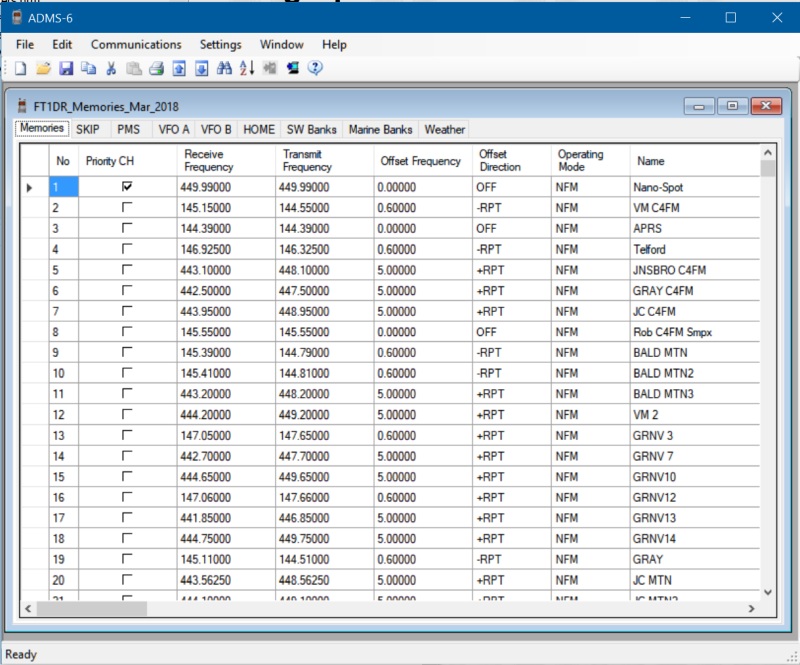
The hotspot frequency is in row 1. For a hotspot that transmits and receives on a single frequency such as a typical MMDVM_HS_HAT just put the hotspot frequency in both the Receive and Transmit Frequency as shown above. For a duplex MMDVM_HS_DUAL_HAT put the Receive and Transmit Frequencies in the memory.
Troubleshooting YSF
Monitor Pi-Star's dashboard as you transmit and you should see activity in the "Local RF Activity" section. If you don't:
Use an analog radio to monitor the hotspot and radio's transmissions. YSF has a white noise static sound to it. It does not sound "digital".
Verify you're using VFO 1.
Verify the radio transmit mode is showing "DN" (digital narrow) on the display.
Check the radio and hotspot frequencies are the same.
If using a simplex hotspot, make sure your radio is in simplex mode when using the hotspot. If you put your hotspot frequency in a repeater band your radio may automatically switch into repeater mode and transmit on the wrong frequency.
Pi-Star's Admin/Live Logs display will give you more detail on what the hotspot is doing.
Excessive "Loss" (shown on Pi-Star dashboard) means data loss on data incoming from the internet. If your radio transmissions to the hotspot show a high loss then the hotspot's connection to the internet has a problem. If only other callsigns show high loss then they have a connection problem.
See this to adjust and tune your hotspot's RXOffset & TXOffset for lowest reception bit error rate (Local RF Activity BER). An incorrect setting can prevent your radio from decoding your hotspot's transmissions.
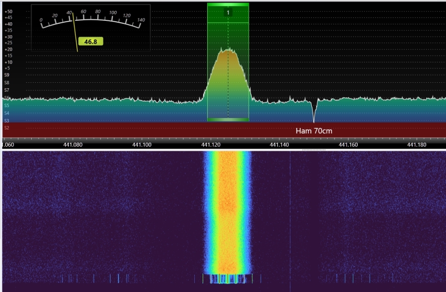
YSF Modulation

Notice the broad, thick, solid waterfall signal. YSF uses 12.5kHz of bandwidth like DMR & P25. YSF sounds very similar to P25 because they both use C4FM and sound like soft static.
YSF uses C4FM (Continuous 4-level Frequency Shift Keying & Frequency Modulation) digital modulation like P25 but the two standards are not compatible.
D-STAR
Programming my Kenwood TH-D74 for hotspot D-STAR was difficult with lots of little details that if you get wrong will keep you from communicating with the hotspot. You need to start with registering for D-STAR repeater access so you can use net-linked D-STAR repeaters.
You must enter your callsign into the radio's "Menu (Digital)-TX/RX" page. There is no "D-STAR ID" like DMR and P25 use.
D-STAR Callsign
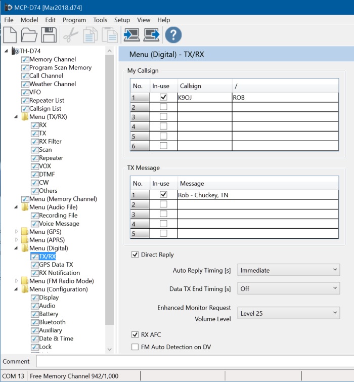
Enter your callsign in the Menu (Digital)-TX/RX page. When using D-STAR my callsign goes out as "K9OJ/ROB" which is a common D-STAR technique.
D-STAR Memory Programming
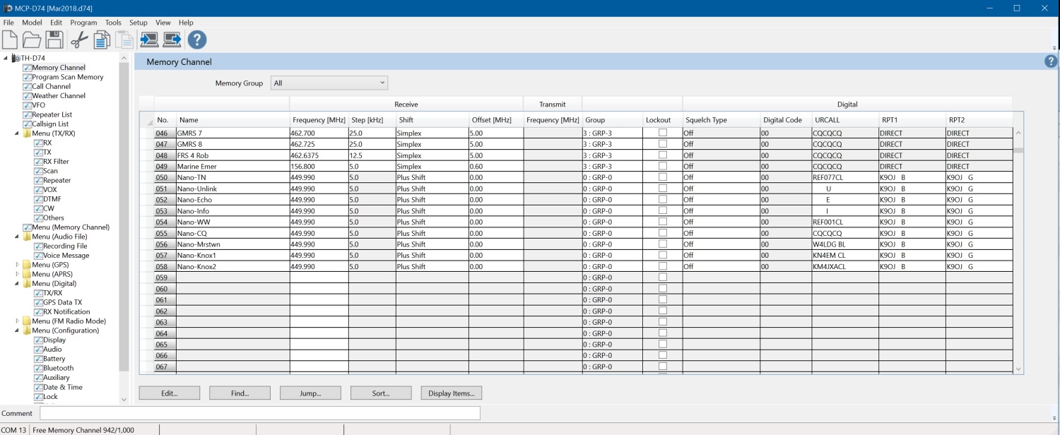
The hotspot channels run from row 50 to 58.
When programming radio memories you must select the "DR" Digital Repeater mode.
You must also select a "Plus Shift" or "Minus Shift" with a 0MHz offset as shown above (I know, it's weird).
Memory 50 above, "Nano-TN" is the Tennessee-wide Reflector 077C. Notice the "URCALL" column "REF077CL" means "Link to Reflector 077 C module". The "C" must be in the 7th character spot and the "L" must be in the 8th spot.
At far right above, "RPT1" and "RPT2" is where we tell the radio about the hotspot. "K9OJ" is the hotspot callsign and should match what you have in Pi-Star under "General Configuration - Node Callsign". The "B" says to communicate with the "B" module and the "G" means connect through the hotspot's Gateway. The B & G must be in the 8th character spot (I have 3 spaces between my callsign and the B & G). If your hotspot uses VHF then you may need to use "C" instead of "B" (B=70cm, C=2m). RPT1 and RPT2 should match what you have in the Pi-Star D-STAR configuration section, "RPT1 Callsign" & "RPT2 Callsign".
To use the hotspot I select memory 50 (Reflector 077 module C) and transmit for a couple of seconds to get linked to the reflector. The radio will say "Linked to xxxxxx". This step isn't necessary if you have Pi-Star configured to connect to a default D-STAR reflector at startup. Then I change the channel to the talkgroup I want to speak with and transmit.
I use channel 51 (Unlink) to disconnect my hotspot from the reflector or talkgroup when I'm done. Channel 52 is the "parrot" or Echo talkgroup for testing the hotspot and radio. Channel 53 (Info) will make the hotspot tell you the link status. In the URCALL field the U, E and I must have 7 spaces in front of it so it is the 8th character.
Channel 54 is Reflector 001C world-wide. Channel 56 is the Morristown, Tennessee D-STAR repeater. Notice how there is a space between the repeater callsign "W4LDG" and the "CL" (Link to the C module) command because the CL must occupy the 7th & 8th character position in the URCALL column. For most repeaters the B module is a 70cm repeater and the C module is a 2 meter repeater.
Troubleshooting D-STAR
Monitor Pi-Star's dashboard when you transmit and you should see activity in the "Local RF Activity" section. If you don't:
Use an analog radio to monitor the hotspot and radio's transmissions. D-STAR sounds like a typical digital transmission.
Verify the D-STAR Callsign is set in the radio.
Check the memory's Shift & Offset are set for 0 offset.
Verify the memory's URCALL has the "B" or "C" in the 7th character position and the L, U, E or I in the 8th position.
Check the memory's RPT1 and RPT2 has the "B" and "G" in the 8th character position.
Verify the radio transmit mode is set to D-STAR.
Check the radio and hotspot frequencies are the same.
If using a simplex hotspot, make sure your radio is in simplex mode when using the hotspot. If you put your hotspot frequency in a repeater band your radio may automatically switch into repeater mode and transmit on the wrong frequency.
If you cannot connect to a D-STAR reflector in Pi-Star verify your D-STAR registration is complete. After registering you have to get approved and then log in to complete your registration.
Pi-Star's "Admin/Live Logs" display will give you more detail on what the hotspot is doing.
Excessive "Loss" (shown on Pi-Star dashboard) means data loss on data incoming from the internet. If your radio transmissions to the hotspot show a high loss then the hotspot's connection to the internet has a problem. If only other callsigns show high loss then they have a connection problem.
See this to adjust and tune your hotspot's RXOffset & TXOffset for lowest reception bit error rate (Local RF Activity BER). An incorrect setting can prevent your radio from decoding your hotspot's transmissions.
D-STAR Modulation
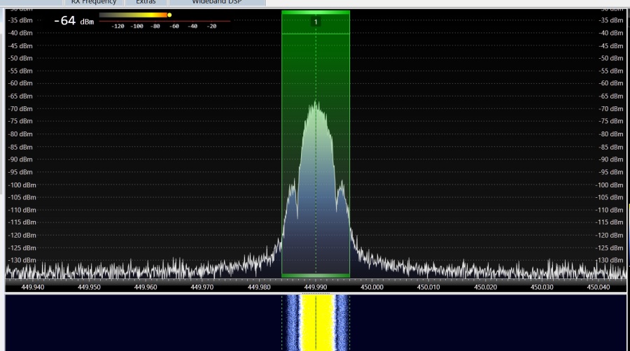
Notice the "shoulders" and solid waterfall signal. D-STAR is noticeably thinner on the waterfall display due to its 6.25kHz bandwidth. The other digital modes use 12.5kHz of bandwidth. D-STAR sounds like a "typical" digital signal.
D-STAR stands for Digital Smart Technologies for Amateur Radio. It was developed by the Japan Amateur Radio League and uses Gaussian Minimum Shift Keying (GMSK) digital modulation.
DMR
I really like my Tytera MD-380 DMR UHF radio but it wasn't easy getting it to work with the hotspot.
You have to set your DMR ID in the Pi-Star configuration page and in the radio. If you don't have a DMR ID you can register for your DMR ID here.
Programming memories into a DMR radio is a three step process. You first create "Digital Contacts", then put those digital contacts into "Channels", then put the Channels into a Zone. A Zone is just a grouping of channels.
DMR Memory Programming Digital Contacts
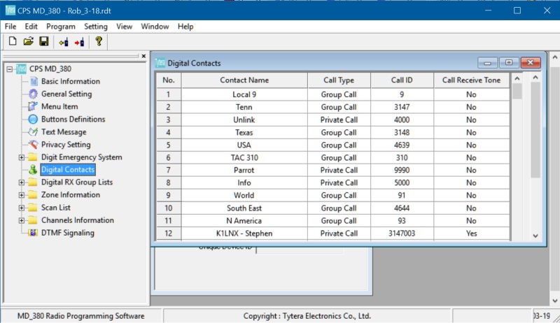
After setting your DMR ID in the radio's "General Setting" page, program your talkgroups in the "Digital Contacts" section. The "Call ID" is the talkgroup number. Use "Private Call" for BrandMeister reflectors, status or pistar remote commands, all other DMR hotspot "Digital Contacts" should use "Group Call".
DMR Memory Programming Channel Information
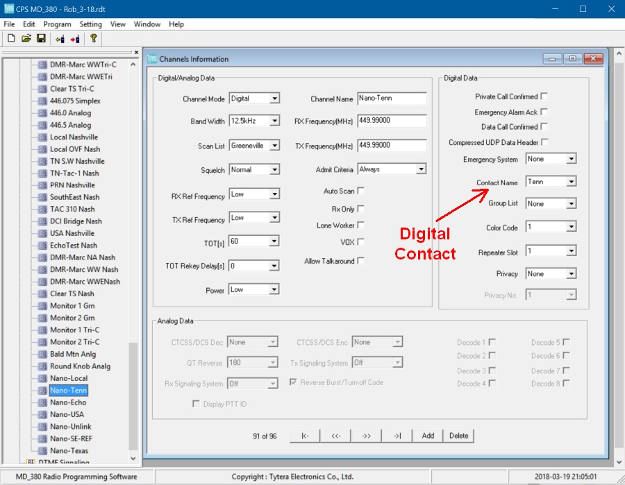
After entering your "Digital Contacts" above you can plug them into the "Contact Name" field of the "Channel Information" page. Note the "Channel Mode:Digital", "Color Code:1", "Repeater Slot (time slot):1" and "Privacy:None" fields.
I created "Nano-Local" talkgroup 9, "Nano-Echo" parrot, "Nano-USA" USA-wide talkgroup, "Nano-Unlink" talkgroup 4000, "Nano-Info" talkgroup 5000, "Nano-SE-REF" Southeast USA Reflector and "Nano-Texas" Texas-wide talkgroup channels.
DMR Memory Programming Zone Information
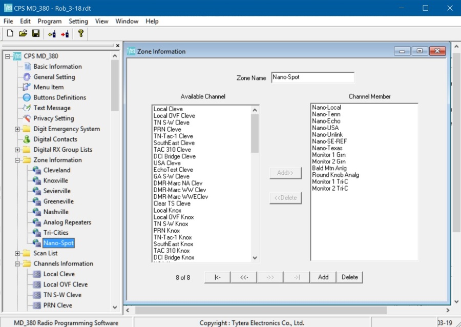
The last thing to do is to create a "Hotspot" zone and fill it with the channels you created above. A zone is simply a grouping of channels.
BrandMeister Controls in Pi-Star
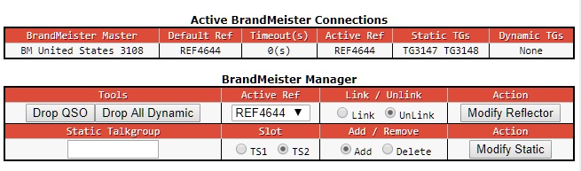
You can change several DMR BrandMeister controls using Pi-Star's "Admin" dashboard.
I recommend you register with BrandMeister and use their reflectors. I set Pi-Star's "DMR Master" to "BM_United_States_3108" (Atlanta).
If you use your hotspot with a phone then the BrandMeister Device Manager Android app can help you drop calls and dynamic talk groups very easily.
To use the hotspot press the MD-380's Menu key to select the hotspot zone.
Turn the radio selector knob to select a reflector. I use BM-SE-REF as my default reflector. Then transmit for about two seconds to link to the reflector. The radio will say, "Linked to xxxxx".
Once linked turn the selector knob to select a talk group if you don't want to speak through the reflector.
DMR talkgroup 3147 is Tennessee-wide. 3148 is Texas-wide, 4639 is USA-wide and 91 is World-wide
We typically use Repeater Slot 1 (time slot 1) and Group Call (not Private Call) for most talk groups.
4xxx talk groups are actually reflectors which can be set as the default reflector.
Once you register with BrandMeister you can edit your hotspot's info for others to see.
You can manually select a new talkgroup on-the-fly in the Tytera MD-380 by hitting the radio's Menu key, selecting Contacts, keying in the talkgroup number (numbers only, no "TG"), then pressing the PTT button to connect.
Troubleshooting DMR
Monitor Pi-Star's dashboard when you transmit and you should see activity in the "Local RF Activity" section. If you don't:
Use an analog radio to monitor the hotspot and radio's transmissions. DMR sounds like digital static.
Verify the DMR ID is properly set
Check the memory's Channel Mode is set to "Digital"
Verify the memory's Contact Name is correct
Check the memory's Color Code is set to 1
Verify the memory's Repeater Slot (time slot) is correct
Check the memory's Privacy is set to "None"
Verify the memory and radio frequencies are the same.
If using a simplex hotspot, make sure your radio is in simplex mode when using the hotspot. If you put your hotspot frequency in a repeater band your radio may automatically switch into repeater mode and transmit on the wrong frequency.
Pi-Star's "Admin/Live Logs" display will give you more detail on what the hotspot is doing.
Excessive "Loss" (shown on Pi-Star dashboard) means data loss on data incoming from the internet. If your radio transmissions to the hotspot show a high loss then the hotspot's connection to the internet has a problem. If only other callsigns show high loss then they have a connection problem. You may be able to decrease your Loss % in DMR by increasing Pi-Star's Configuration / Expert / MMDVMHost / DMR Network / Jitter from 300 to 700.
See this to adjust and tune your hotspot's RXOffset & TXOffset for lowest reception bit error rate (Local RF Activity BER). An incorrect setting can prevent your radio from decoding your hotspot's transmissions.
DMR Modulation
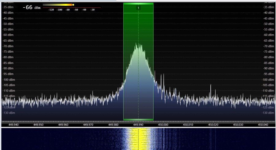
Notice the bands in the waterfall signal which make the signal sound choppy. They were caused by a bug in the MMDVM firmware which has been fixed. DMR uses12.5kHz of bandwidth and sounds like digital static.
DMR stands for Digital Mobile Radio and uses Four-state Frequency Shift Keying (4FSK) digital modulation with Time Division Multiple Access (TDMA) to create two time slots.
P25
Commercial P25 radios are very cool and I love the Motorola XTS3000 P25 radio I purchased on eBay. It's a heavy but rock-solid radio that thousands of police and firemen have relied upon for rugged reliable service. There are brand-new housings available for many Motorola P25 radios so you can completely refurbish their look. There are also brand-new batteries and accessories available. The XTS3000 Model I comes with no display or front panel buttons. The Model II has a display and six buttons and the Model III has a display and full keypad. I purchased a used Model II for $169. The XTS3000 comes in VHF, 700/800MHz and two UHF models. The UHF models put out around 4 watts on high and 1 watt on the low setting.
Motorola XTS3000 P25 UHF Radio
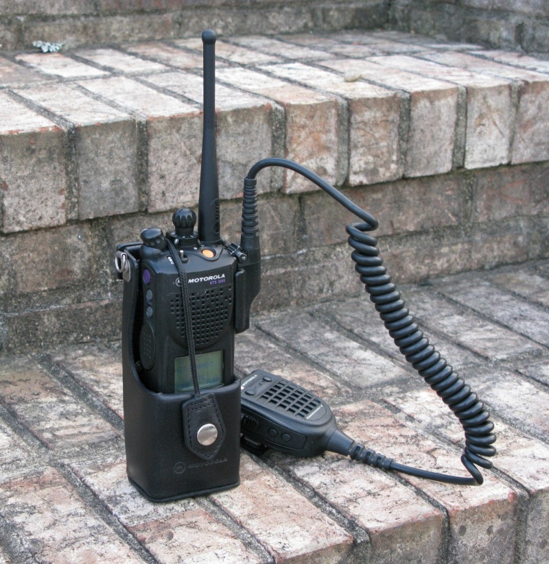
The first thing I did wrong was to purchase an XTS3000 UHF Range II with a frequency band of 450 to 520MHz. I didn't realize there were two UHF versions of the XTS3000. Luckily the radio will function just fine on 449.990MHz so that's where I set my hotspot frequency. If you go too far out of the radio's band the CPS programming software won't write the code plug to the radio so I can't use this radio for P25 repeaters. Fun fact: The XTS3000 uses the same antennas, microphones, batteries and charger as the newer XTS5000 but the programming cables and software are different.
The correct UHF radio version for hams would be "UHF Range 1" which covers 403 to 470MHz. Range 1 radios are also referred to as "R Split" radios. Range II radios cover 450- 520MHz and are called "S Split". I was later able to extend my Range II radio's band down to 440MHz for use with ham repeaters, see Modifying Astro CPS for more info. Later I broke down and purchased a nice Range 1 R Split radio for ham use.
You'll also need a programming cable for the radio. The XTS3000 uses a "Ribless" cable. RIB stands for "radio interface box" and "RIBless" means you don't need a RIB. Ebay sells the cables for around $25 but make sure the seller mentions XTS3000 in the add because the XTS5000 RIBless cable will not work with the XTS3000. The cable clips to the left side of the radio and has either a serial or USB connector to connect to your computer. Mine has a 9-pin serial COM port connector and I use a USB-to-serial adapter with it. I had to set the USB-to-serial adapter for XON-XOFF flow control inside Windows's Device Manager to make it recognize the radio.
The next thing I did wrong was purchase an incorrect version of the Motorola CPS (Customer Programming Software). I ordered the current version which doesn't cover older radios like my XTS3000. After doing some research I found what I was looking for. You can download the Astro Saber and XTS3000 CPS programming software here. The software is no longer available from Motorola.
There is also an Astro 25 CPS version for the XTS2500 and XTS5000. There are also other versions of CPS for newer radios available on eBay so do some research before you buy programming software.
Astro Saber & XTS3000 CPS software only works on 32 bit Windows XP, Vista or Windows 7. I loaded an old laptop with downloaded copy of Windows 7 Ultimate x86 (32 bit). I also had to download the driver for my MaxtonData USB-Motorola Ribless Cable (has real FTDI USB chip) and it worked like a champ with XTS3000 CPS. Use Window's Device Manager/Ports to see what COM port the serial port is using (for real RS232 port or USB-to-serial adapter). You have to set this COM port number in CPS to establish contact between the computer and radio. Motorola recommends com port settings of: 9600 baud, N81, Flow Control=None, Advanced Settings: un-check "Use FIFO buffers," set these in Windows Device Manager under "Ports." Others have reported success using a Linux computer with a Windows XP virtual machine.
Once I got the correct version of CPS and had the USB-to-serial adapter working it was time to program the radio. P25 radio memory is laid out very much like DMR with talkgroups, channels and zones.
The first thing you should do once you are hooked up is to read the radio data into CPS. I highly recommend you save the code plug before you start editing so you can go back to the original programming. Once that is done you can edit and use "Save as" to save the programmed data and you'll be able to write it back to the radio. Always save the CPS programming before you write to the radio.
Programming the XTS3000
One of the most common gotcha's of P25 radio programming is forgetting to set your DMR ID in the radio's ID field. Yes, use your DMR ID for P25. For my XTS3000 the ID went into the "Astro System 1/Genera/Individual ID" field. If you don't have a DMR ID you can register for your DMR ID here.
DMR ID In CPS
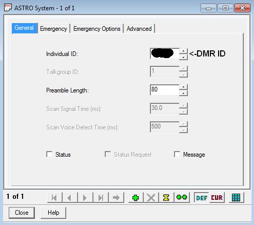
In CPS software click on "Expand All" at the bottom of the page, then double-click on "Astro System - 1" in the left window and enter your DMR ID.
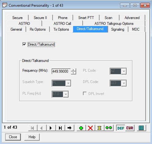
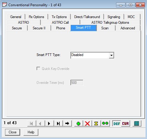
Setup Channels or "Conventional Personalities"

In the CPS software double-click on "Conventional Personality - 1" in the left window. "Conventional Personality" means "non-trunking channel". Set the transmit and receive frequencies.
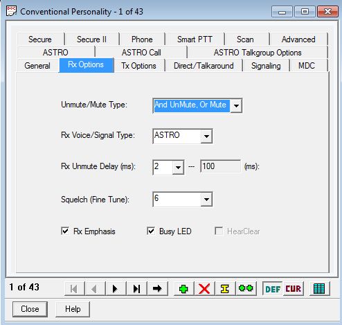
Set "RX Voice/Signal Type" to "ASTRO" for P25.
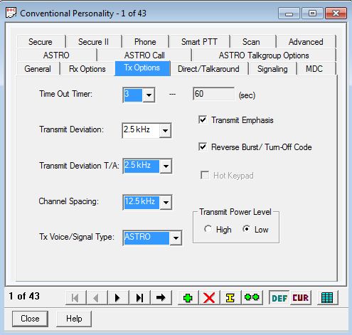
I set the Transmit Power Level to Low for hotspot use and High for repeaters.
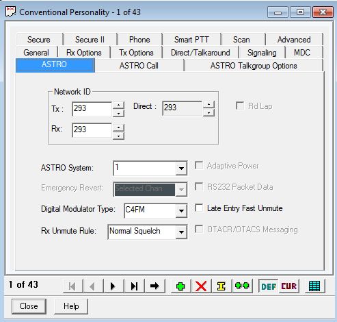
Select "293" for the "Network ID" and "C4FM" for "Digital Modulator Type".
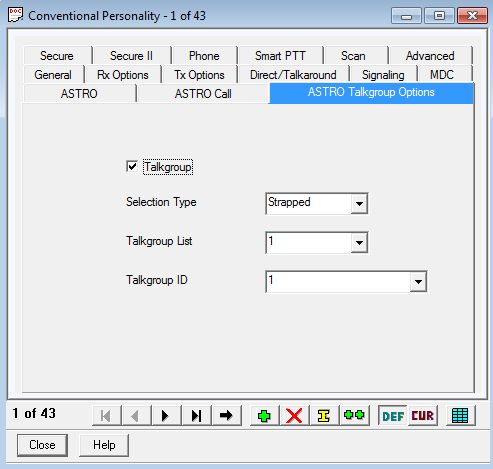
"Strapped" means the talkgroup can't be changed by using the radio buttons.
You have to do the above steps for each talkgroup channel.
Setup Your Talkgroups
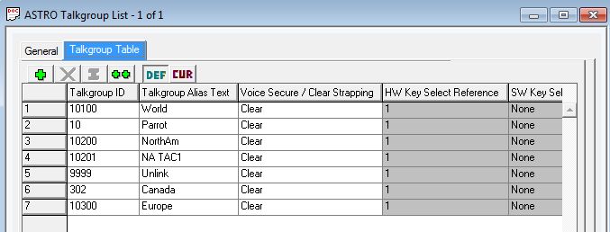
I programmed the following talkgroups: TG10100 world-wide, TG10200 USA, TG9999 is Unlink, TG00010 is Parrot.
Setup Your Hotspot Zone

I named my zone "HOT" for hotspot.
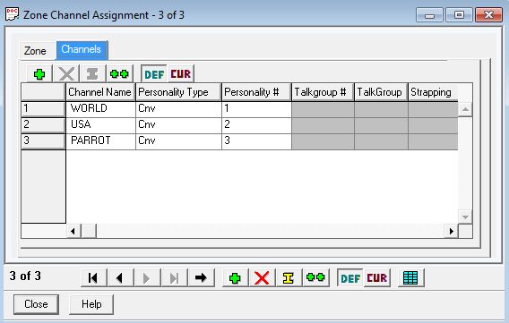
I added the talkgroups to the hotspot zone. A zone is simply a grouping of channels.
Other popular talkgroups include North America TAC1 10201, Canada 302 and Europe 10300.
When you get everything set be sure and save the radio file then "write" the file to the radio. Just connect the radio and turn it on, then click the "Write to Device" button in CPS. The XTS3000 shows "1 CPQ" during data transfer. The radio will reset when finished.
On the radio select the zone, then channel and you're ready to transmit to your hotspot. For my radio Zone 1, Channel 3 is the parrot or echo radio test talkgroup. Anything you transmit to this talkgroup will be sent back to you so you can verify everything works and hear the quality of your audio. Use this to determine how close to hold the radio or mic for best audio.
I like to use the three-position "A B C" switch on top of the radio to select the zone. You do this in the CPS "Controls/Switches" page. You have to put "Zone Select" in both the Conventional and Trunked selections for it to work properly.
Troubleshooting P25
Monitor Pi-Star's dashboard when you transmit and you should see activity in the "Local RF Activity" section. If you don't:
Use an analog radio to monitor the hotspot and radio's transmissions. P25 has a soft white noise static sound to it. It does not sound "digital".
Verify the P25 (DMR) ID is set in the radio.
Check the channel's TX Voice/Signal Type is set to Astro.
Make sure the channel's Digital Modulator Type is set to C4FM.
Verify the channel's Network ID is set to 293 for both transmit and receive.
Check the hotspot and radio frequencies are the same.
If using a simplex hotspot, make sure your radio is in simplex mode when using the hotspot. If you put your hotspot frequency in a repeater band your radio may automatically switch into repeater mode and transmit on the wrong frequency.
Pi-Star's "Admin/Live Logs" display will give you more detail on what the hotspot is doing.
Excessive "Loss" (shown on Pi-Star dashboard) means data loss on data incoming from the internet. If your radio transmissions to the hotspot show a high loss then the hotspot's connection to the internet has a problem. If only other callsigns show high loss then they have a connection problem.
See this to adjust and tune your hotspot's RXOffset & TXOffset for lowest reception bit error rate (Local RF Activity BER). An incorrect setting can prevent your radio from decoding your hotspot's transmissions.
P25 Modulation
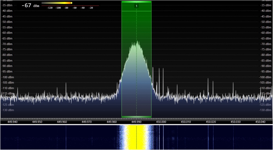
Looks and sounds very similar to YSF because they both use C4FM modulation. P25 uses 12.5kHz of bandwidth like YSF and sounds like soft static.
P25, sometimes called APCO 25 or Pop 25, is short for "Project 25" and uses C4FM (Continuous 4-level Frequency Shift Keying & Frequency Modulation) digital modulation like YSF but the two standards are not compatible.
UPDATE JULY 2025
M17 support in Pistar, WPSD, and soon MMDVM firmware, has been removed. Setting up an M17 hotspot or repeater is no longer as simple as activating it in Pistar or WPSD. More info on this setback can be found on the M17 discord channel.
I was big fan of M17 digital voice because it uses open source for everything, including the vocoder, so there are no restrictions on amateur use like other digital modes that use proprietary vocoders such as DMR, P25 and NXDN. There are several ways to get on the air with M17:
1. Purchase a CSI CS7000-M17 UHF radio which is delivered ready to use M17. The CSI CS7000M17 Plus can do M17, DMR, analog FM, and P25 is in late development. The downside is they have a 12-bit analog-to-digital converter that is upsampled to 16-bit which amplifies noise.
2. Modify a TYT MD-UV380 $75 or Baofeng DM-1701 $40 from Aliexpress.com (both are dual band VHF & UHF) and then flash OpenRTX firmware. A list of M17 compatible radio mods is available here.
3. Plug a digirig computer interface $50 into a 9600 baud capable UHF radio such as the Yaesu FTM-200, 300, 400, 500 or FTM-6000R.
[This paragraph is no longer true with the loss of M17 mode in MMDVM hotspots] The easy way to update MMDVM hotspot firmware for M17 is to use W0CHP's WPSD dashboard. The firmware update command is located at Admin/Advanced/Tools. M17 support requires modem firmware v1.6.0 or higher. If you get a "failure to init" error when you try to flash the firmware, this usually means the modem board's J1 jumper isn't shorted. For most HS HAT boards there is a pair of solder pads labeled "J1" that must be shorted together to allow firmware overwrite. The J1 pads can be shorted together during power-up using metal tweezers or you can simply solder the two pads together. This allows the firmware to be overwritten and flashed at any time without using tweezers but be aware that some modem boards will not function if you solder the firmware jumper pads together.
TYT MD-UV380 and UV390 (with or without GPS) radios no longer suffer from low audio output. The firmware has been updated and now the volume knob works and will get LOUD. Also, all radio settings persist after a power cycle.
Before I modified my MD-UV380G I used DroidStar to test M17 mode in Pi-Star. M17 works perfectly on DroidStar and does not require a vocoder download.
DroidStar Main Tab For Working M17
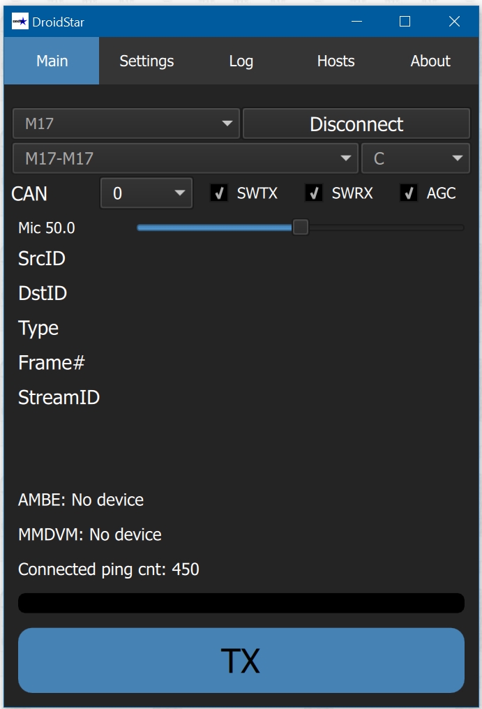
Mode is "M17", reflector is "M17-M17", the module is "C" and the CAN (Channel Access Number) is 0. The M17-M17 module C reflector is one of the more active reflectors. You will find most of the M17 developers monitor it. CAN is normally set to 0.
To use M17 on an OpenRTX MD-380 or MD-UV380 you have to set your call sign in the radio. The green button acts as the "enter key" and the red button acts as the "back" key. To set your callsign you hit the green button, arrow down to "Settings", green button, arrow down to "M17", green button, set call sign then green button. You will also need to set the receive and transmit frequencies using the radio number keys. With the frequency showing, enter your receive frequency and hit the green key, then if your transmit frequency is different from the receive frequency, key in the transmit frequency and hit the green key. To change the destination from "#ALL" just hit the "#" key and type in a callsign, "ECHO" or "ALL" then hit the green key.
M17-M17 module C, CAN 0 is set in my repeater and it's where I used to hang out. It's one of the most used M17 reflectors and holds a net every Friday at noon Eastern Time. The M17 developers hang out there too.
CAN is Channel Access Number and your radio will not break squelch unless the transmit and receive CAN matches. CAN 0 is the default.
In W0CHP's dashboard you can set the M17 reflector using the Admin page M17 Manager. [No longer true]
M17 Modulation
M17 uses Four-state Frequency Shift Keying (4FSK) running at 4800 symbols/sec (9600 bits/sec) in 9 kHz of bandwidth with 12.5kHz channel spacing (FM-Narrow). Like DMR, M17 uses 4FSK but the two standards are not compatible. M17 sounds like DMR--like digital static.
Using Digirig for M17 Transmit and Reception
You can get on the air with M17 using a $50 digirig mobile radio-computer interface and a 9600 baud capable UHF radio. I used a Yaesu FTM-200DR (VHF/UHF dual band Fusion mobile) but most modern UHF radios with a 9600 baud modem port will work with a digirig for M17. The inexpensive Yaesu FTM-6000R (no Fusion mode) is a known performer on M17. I tried a 20+ year old Kenwood TM-733A dual band mobile that has a 9600 baud modem port but it was too unstable for a solid M17 signal.
I used the free m17-tools M17-RTX Gui software to take audio to-and-from the computer microphone and speakers. There are Windows and Linux versions of m17-tools.
The digirig mobile is similar to a SignaLink radio-computer interface but the digirig is certified for M17 voice as well as other digital modes. I used the $30 digirig Yaesu MiniDin10 9600-baud cable to go between the digirig mobile and my radio so no soldering was required for this project. To work with M17 the radio must have a 9600 baud interface or access to discriminator level unfiltered, flat audio, usually through hardware modification. My FTM-200DR has a 9600 baud modem port that is used by digirig.
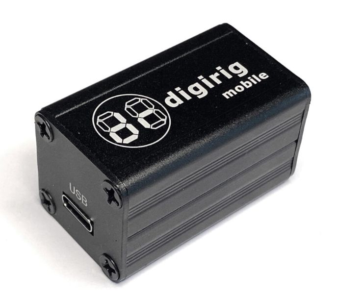
digirig mobile computer-radio interface for ham digital modes.
I used SDR++ SDR software with its M17 module to set the M17 deviation on both my hotspot and the FTM-200DR radio. The M17 module just needs to be turned on in the SDR++ Module Manager.
The first thing I did was set the M17 deviation of my hotspot by adjusting the value of MMDVMHost/Modem/M17TXLevel and monitoring the SDR++ M17 module display during hotspot M17 transmit. For me a value of 40 gave me the best deviation plot on SDR++ M17 display (see screen capture below). I used M17TXLevel to adjust the deviation because I didn t want to affect the deviation of the other modes by changing the global TXLevel.
SDR++ M17 Module Display
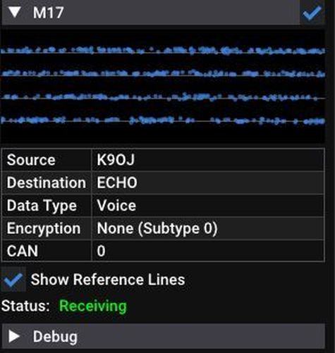
SDR++ M17 module display showing good deviation from my hotspot. The transmit lines in the graph overlay the reference lines. Since the display shows my callsign, destination, data type, encryption and CAN we know the M17 signal is being at least partially decoded.
After setting the hotspot M17 deviation I pluged in the digirig mobile using the pre-made radio interface cable from digirig. The cable plugs into the 10 pin DIN connector on the back of the radio. I then plugged the digirig USB cable into my computer.
Next I checked Windows Device Manager to see what com port was assigned to the digirig (Com 3 on my computer). I then set the Windows/Settings/Sound sound levels to 100 (max) for my desktop microphone, the digirig Mic (digirig In) and digirig Speakers (digirig Out). Turn off any Windows sound effects such as spatial or 3D sound for the digirig input and output.
I started up the M17-RTX Gui app by double-clicking m17-mod-gui.exe located in the m17-tools folder and set the Rig Control tab.
M17-RTX Gui App
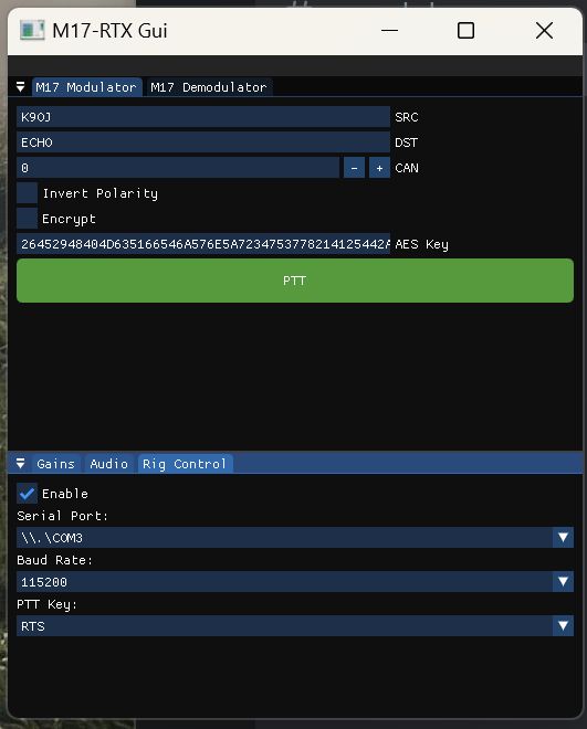
My Rig Control tab (bottom half). Windows Device Manager showed COM3 as the digirig com port. 115200 Baud Rate and RTS work for the digirig and my radio. You will also need to enter your call sign in SRC. Note I changed the destination (DST) from All to ECHO for testing. Encryption also works, just enter a 64 digit hex number in AES Key and check the Encrypt checkbox. Encryption will then be used for both transmit and receive. You can select M17 Modulator (transmit) or M17 Demodulator (receive) on the top tabs. Receive will automatically activate when you stop transmitting but you can also manually turn on the receiver in the M17 Demodulator tab.
Next I selected the Audio tab and set the mic, digirig input and output, and speakers to use with the app.
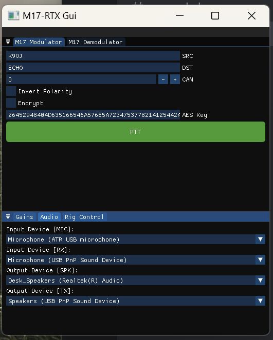
My Audio tab. The ATR USB microphone is my desk mic. "Microphone (USB PnP Sound Device)" is the digirig input. "Desk_Speakers" are my desktop speakers. "Speakers (USB PnP Sound Device)" is the digirig output to the radio.
Setting the Gain Sliders
Click on the M17-RTX Gui Gains tab. Mic Gain is for your actual microphone and I needed max gain for my ATR desk mic. Rx Gain sets the volume into the radio interface (digirig in my case). Speaker Gain sets the volume out of the speakers you listen with. Tx Gain sets the volume going into the radio and therefore sets the transmit deviation. You must adjust the Tx Gain and Rx Gain sliders for proper transmit and reception deviation. My final gain settings were: Mic Gain 1.0, Rx Gain 0.42, Speaker Gain 1.0 and Tx Gain 0.83
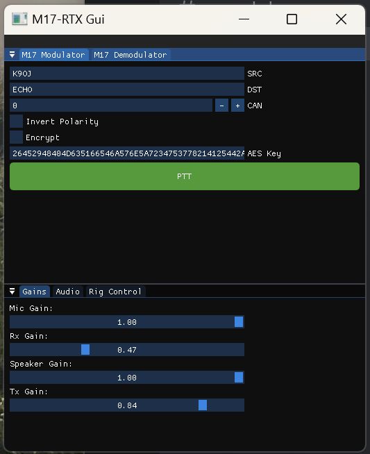
My Gain Tab Settings.
I set the M17-RTX Gui Tx Gain by using the ECHO destination (see DST in the above screen capture). Anything you transmit to ECHO will be transmitted back to you so it's great for testing and setup. While transmitting with my radio to my hotspot with ECHO set I adjusted the TX Gain slider until the SDR++ M17 graph of my M17 radio signal shows the transmit lines on top of the reference lines (see screen capture below). A Tx Gain setting of 0.83 gave me an average of 95% transmit deviation. Make sure Show Reference Lines is checked at the bottom of the SDR++ M17 Module window.
SDR++ M17 Module Display
SDR++ M17 module display. This shows a pretty good deviation setting of my FTM-200DR. The transmit lines in the display overlay the reference lines. Since the display shows my callsign, destination, data type, encryption and CAN we know the M17 signal is being at least partially decoded. "Show Reference Lines" must be checked to set M17 deviation.
With TX Gain set I could then set Rx Gain by adjusting the Rx Gain slider during reception from the hotspot until I got about 95% average deviation shown on the M17-RTX Gui Demodulator page. An Rx Gain setting of 0.42 gave me 95% average reception deviation.
Demodulator Tab
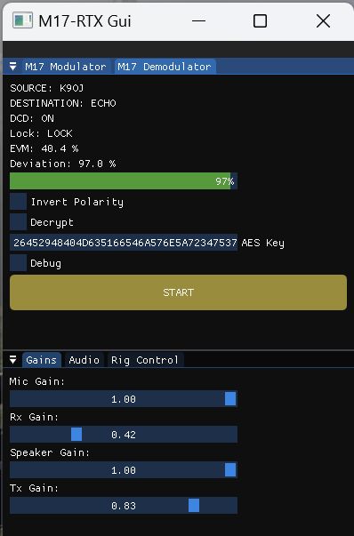
Use the green Deviation bar to set the RX Gain slider during M17 signal reception.
Just click the M17-RTX Gui PTT button and it will latch on transmit until you click PTT again to end transmission. The digirig mobile will control radio transmit through its COM port. I m showing a BER (Bit Error Rate) of 0.0% when communicating with my hotspot and audio is good from my FTM-200DR.
The $300 Yaesu FTM-6000R has also been used successfully with a digirig mobile for M17. As a general rule of thumb, if a UHF radio has a digital mode built in and has a 9600 baud modem port then it will work with M17 and digirig. The Mobilink TNC4 is M17 data mode compatible out of the box so it might work with M17-RTX Gui for M17 voice too.
Encryption using M17-RTX Gui works great too. Just set a 64 digit hex AES encryption key and click the Encrypt check box. Encrypted audio sounds the same as normal (as it should). I did have to add AllowEncryption=1 in the M17 section of my hotspot's MMDVM.ini just after TXHang.
Hope this helps some of you get on the air with M17 using a digirig and a 9600-baud capable radio.
Building an M17 Repeater
[With the removal of M17 mode in MMDVM based repeater controllers, creating an M17 repeater is no longer easy] In June 2023 I put together an M17 UHF repeater to try to promote M17 use in my local area. The first thing I did was coordinate with my local repeater coordinators sera.org. After studying the local repeaters in my area I requested an open pair of repeater frequencies. The next day I was assigned a repeater pair that was slightly different than what I requested. With my frequencies firmed up I could begin sourcing the repeater parts.
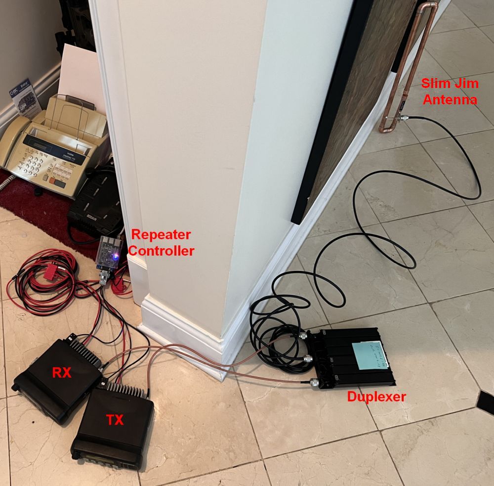
The repeater during testing. The repeater controller is connected to the two radios with a pre-built cable from Repeater Builder. The radio antenna connectors are attached to the two outside connectors on the duplexer. The center duplexer connector goes to the antenna. The duplexer needs no external power. Its inputs are labeled "TX", "ANT", "RX" but most are labeled "Low", "Ant", and "High". The 12 volt 30 amp DC power supply for the radios is out of sight near the repeater controller. I'm now using a Comet CA-712EF UHF Base Vertical Antenna with the repeater. It's 10 feet tall and has 9.8dbi of gain.
My repeater is made up of these components:
Repeater Controller: Old repeater controllers were expensive and could be difficult to use. With the advent of easy-to-use pi-star hotspot software and inexpensive Raspberry Pi hat based MMDVM hotspot boards, repeater controllers are now inexpensive and easy to use. I went with a $95 Repeater Builder STM32_DVM_PiHat mounted on a raspberry pi 3+ computer. The STM32_DVM is similar to standard MMDVM pi hat hotspot boards, except that it does not have built-in radios. It's made to use external radios, and supports FM Analog mode. One quirk is that you cannot solder the "J1 flash enable" solder pads. If you solder the J1 pads the board will not function. To flash firmware you have to short the J1 solder pads temporarily with a piece of wire or metal tweezers during board startup (keep shorted for about 5 seconds after powering up the pi). The STM32_DVM can do all modes that pi-star supports including M17, DMR, D-STAR, Fusion, P25, NXDN, cross modes, AX.25, POCSAG, and adds analog FM mode. I upgraded the STM32_DVM firmware to 1.6.0 for M17 support following these instructions.
Repeater Controller Software: [With the removal of M17 mode in MMDVM based repeater controllers, PiStar and WPSD no longer support M17] W0CHP WPSD dashboard based on pi-star, runs on the repeater controller's raspberry pi 3+. The pi 3+ is the weakest computer I recommend for use with the WPSD dashboard. The pi 4 runs the dashboard much better (the Pi 5 has some incompatibility issues). The WPSD dashboard supports M17 without modification. Chip's WPSD dashboard is far superior to the standard pi-star dashboard. To enable M17 in the dashboard, select "M17" in the main configuration page, click on "Apply Changes," then set your default reflector, callsign suffix (I use "R" for repeater and "H" for hotspot), station ID (blank) and CAN (0 is default) and click "Apply Changes".
My WPSD Settings
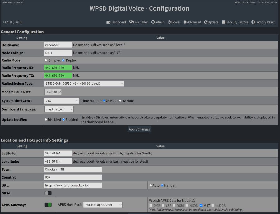
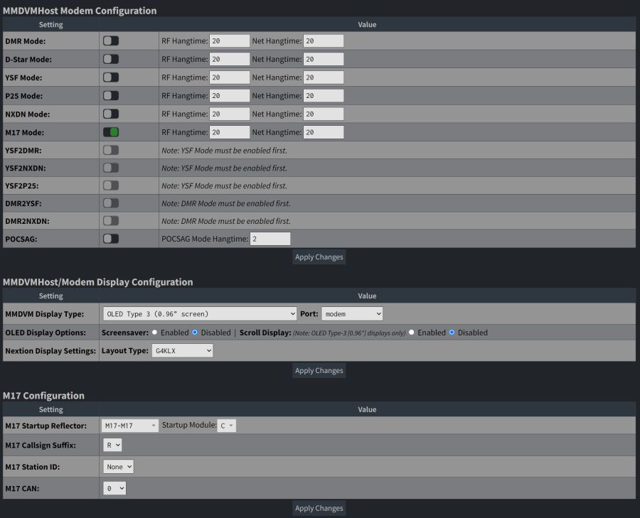
M17 configuration at the bottom of the page. The M17-M17 reflector is the busiest M17 reflector and you'll always find someone willing to chat. The C module is where most users hang out. Callsign Suffix and Station Id are optional. CAN is usually 0.
The WPSD dashboard will pass encrypted M17 if you edit Configuration/Advanced/Full Editor/MMDVMHost and add AllowEncryption=1 in the M17 section just after TXHang. Encryption is legal in the US as long as the purpose of the encryption isn't to obscure the meaning of the transmission, which means testing encryption is perfectly legal. It can also be used to transmit sensitive personal information during an emergency response.
You can also run FM Analog mode along with M17 by enabling FM in the Configuration/Advanced/Quick Editors/MMDVMHost file near the bottom of the page, Enable=1. If you do run FM Analog I highly recommend you use a CTCSS input tone because it will make mode changing between M17 and FM Analog much quicker (M17 does not need a tone). To require a CTCSS tone for FM Analog edit the FM section tone settings of the Configuration/Advanced/Quick Editors/MMDVMHost file. To make switching between FM and M17 happen after 20 seconds, I had to set Configuration/Advanced/Quick Editors/MMDVMHost RFModeHang and NetModeHang to 20 seconds. Check the other digital modes' hang times and verify they are also set to 20.
M17 and FM Analog modes are enabled on my repeater. FM Analog activity does not show on the dashboard.
Radios: Two used Motorola CDM1550 LS+ UHF mobile radios (403 - 470MHz R Range) that cost only $155 each. I recommend you run these 50 watt radios on 20 watt low power to keep the transmit radio from overheating since digital repeaters can run at a higher duty cycle than a typical FM mobile radio. A small fan blowing on the transmit radio's heat sink fins is also a good idea. Free CPS programming software for the CDM1550 LS+ can be found by searching for "HVN9025_v6.12.05.zip". Here is the radio user guide. Motorola CDM1250 radios are also very popular for repeater use and are very similar in operation to the CDM1550 LS+ radios.
Power Supply: You will need a 12 volt 20+ amp DC power supply to run the radios at up to 50 watts output power.
Repeater Controller to Radio Interface Cables: Repeater Builder pre-built duplex cable, order the "Dual 16 pin connectors to turn *TWO* Motorola mobiles into a repeater". The cable plugs into both radios and the repeater controller (no soldering required). This cable makes it super easy to connect the repeater controller to the radios with zero soldering required. Order the "Dual 16-pin for two Motorola mobiles" cable for use with CDM1550 LS+ and CDM1250 radios and other Motorola radios with a 16 or 20 pin data connector.
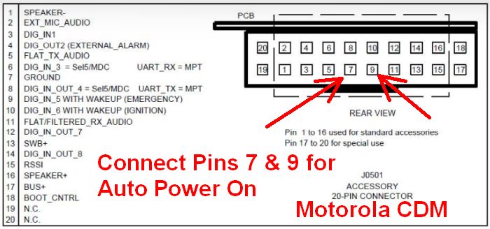
To make CDM radios turn on automatically after a power interruption, you must modify the Radio Interface Cable. Connect pin 7 GND to pin 9 WAKEUP EMERGENCY on both cable radio connectors (see pic below). The correct way to do this is to get two pins for the radio connector (Digikey part # A25989-ND) and solder a short piece of bare wire to them. Then insert the pins into the Pin 9 connector socket from the rear and solder the new thin bare wire to the wire in pin 7 (Ground). Since I didn't have any connector pins I cut a short bare single strand wire, put a slight bend in it so it would make good contact with the radio pin, inserted it into the Pin 9 socket and soldered it to the Pin 7 (Ground) wire (see pic below). The radios must have the Radio Configuration/Accessory Configuration/Ignition Sense set to On/Off & Ignition. If it is not set then use CPS to make the change.
Motorola CDM Radio Pin Out
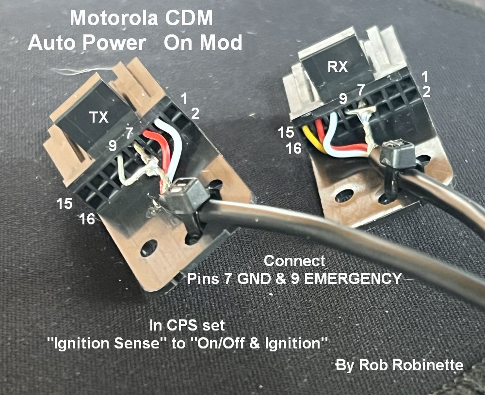
Bare wire with slight bend inserted into the Pin 9 (WAKEUP EMERGENCY) socket and then soldered to the Pin 7 (GROUND) wire.
Coax: Need two, 2 to 3 feet long coax cables from radios to duplexer and a cable from duplexer to antenna. I recommend LMR400, RG-8, RG-213 or RG-214 due to their double copper strand shield which minimizes repeater "desense" from leakage through the coax shield. Don't skimp on cable here. RG58 will not hack it and you'll lose a lot of repeater range due to desense. Make sure the cable connectors match your radios, duplexer and antenna. The CDM1550 LS+ radios have a female Mini-UHF connector and my duplexer and antenna have female N connectors. N connectors are the best RF cable connectors so I purchased a duplexer and antenna with them. You can purchase pre-made custom length RG-213 cable with the connectors of your choice from Amazon and ebay. I went with super high quality DX Engineering 400MAX Type N Low-Loss 50-ohm Coax Assemblies DXE-400MAXDN025 for the run from duplexer to antenna.
Antenna: I went with a Comet CA-712EF UHF Base Vertical Antenna. It's 10 feet tall and has 9.8dbi of gain. It's a strong performer.
Radio programming cable and free Motorola CPS programming software: I used this Motorola programming cable for the CDM1550 LS+ radios. There is also a generic 8-in-1 USB Programming Cable with a mic connector that also works with Motorola radios. Free CPS programming software for the CDM1550 LS+ can be found by searching for "HVN9025_v6.12.05.zip". This CPS software runs on Windows 11 and many older versions of Windows. Program the receive frequency in one memory in the RX radio and program the transmit frequency in the TX radio. Set transmit power to low to keep from overheating the transmit radio and set transmit and receive audio to flat (required for data modes). Also set Radio Configuration/Accessory Configuration/Ignition Sense to On/Off & Ignition. Label the radios "Transmit" and "Receive".
The Duplexer
The duplexer is by far the most expensive part of a low power repeater and consumed almost 50% of my repeater budget. I bought a used Radio Frequency Systems (RFS but also sold as Celwave and Motorola) 633-6A-2N 50 watt UHF 450-470MHz duplexer on ebay (N=N connectors) for $480. The duplexer allows both the transmit and receive radios to simultaneously use one antenna. The 633-6A-2N is a triple notch filter duplexer that is tuned so three deep notch filters sit on top of the transmit and receive frequencies to isolate the transmit and receive radios from one another. The notch filters prevent the transmit signal from getting into the receive radio, and keeps the receive signal from getting into the transmit radio. For in-depth info on duplexers, see the duplexer page.
Signal Flow Through the Duplexer
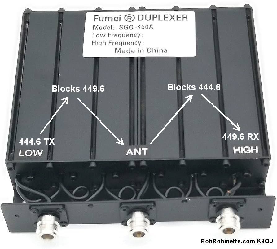
444.6MHz is the repeater transmit frequency, 449.6 is the receive frequency. The signal from the repeater transmitter enters at the left LOW connector, then has 449.6MHz filtered out by the three Low notch filters. The signal then goes out the ANT connector to the repeater antenna. The transmit and receive signals come in from the ANT connector, has the 444.6MHz transmit signal filtered out by the High notch filters, then goes out to the repeater receiver through the HIGH connector. Note that the notch filters work in both directions.
The 633-6A-2N is a pass/reject notch filter duplexer but there are also more expensive band pass filter and band pass reject filter duplexers. Notch filter duplexers are not suitable for repeater sites with other transmitters because they only filter the transmitter they are tuned to, not other nearby transmitters. Use band pass or band pass reject duplexers at sites with multiple transmitters. Band pass reject duplexers are typically what you will find on crowded mountain top repeater sights. Band pass reject duplexers use both pass band pass and notch filters to remove all RF signals except the repeater transmit and receive frequencies. Note that I am using a small, 50 watt UHF duplexer. VHF duplexers are much larger due to wavelength and tight 0.6MHz repeater split. They are typically much more expensive than UHF duplexers. Hamventions are the best place to find good deals on duplexers and other repeater parts.
Large VHF Repeater Duplexer
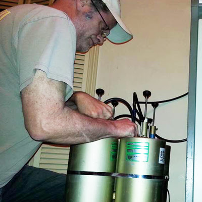
The large tube structures are mechanical resonant cavity filters. Rods with knobs are the cavity tuning adjusters and typically work by changing capacitance to tune the cavity resonant frequency.
You must pay attention to the duplexer's frequency band and minimum frequency split. My 633-6A duplexer is rated for 450-470MHz and 5MHz split (standard UHF repeater split) but it operates well at 444.6 & 449.6MHz. I do not recommend a duplexer that's rated for 470 and higher frequencies--that's just too far away from the Ham band.
50 Watt UHF Repeater Duplexer
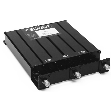
For my M17 UHF repeater I used an RFS/Celwave/Motorola 633-6A-2N UHF 50 watt notch filter duplexer. It has three tuned, resonant cavity notch filters for the transmit frequency, and three tuned, resonant cavity notch filters for the receive frequency. Each cavity creates a notch filter and three notch filters are stacked on top of the transmit and receive frequencies. Duplexers MUST be tuned to the repeater transmit and receive frequencies. The cavity tuning screws are on the other end of the duplexer. The 633-6A-2B model shown above has BNC connectors but the 633-6A-2N comes with N connectors.
Tuning a duplexer requires a service monitor, spectrum analyzer with a tracking generator, or VNA (Vector Network Analyzer). You can always ask your local ham club for help. Our local club has Bob Gass, a very knowledgeable, friendly, and helpful repeater expert that's willing to travel with his service monitor to tune repeater duplexers. You want to tune a duplexer at the repeater site, if possible, because altitude change and bumpy car rides can cause the mechanical duplexer filters to shift off frequency. After tuning, be sure and put a frequency label with the High and Low frequencies on it for future reference.
IFR FM/AM - 1200S Service Monitor
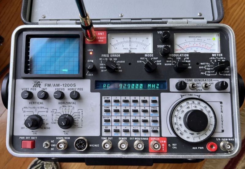
My 1988 IFR 1200S service monitor, shown above, combines a 250kHz-1GHz AM/FM/SSB FCC certified precision receiver and transmitter, spectrum analyzer, tracking generator, RF signal generator, audio tone generator, oscilloscope, and modulation and frequency error displays. It has everything you need to align, adjust and troubleshoot transceivers, repeaters and RF filters. Its tracking generator and spectrum analyzer are used to tune duplexers, filters, combiners, etc. The big difference between this service monitor and a spectrum analyzer + tracking generator (shown below), is the service monitor has an FCC approved, precision calibrated transmitter and receiver used to align and certify transmitters and receivers. The service monitor can also handle 150 watts input, versus 1/4 watt max input for your typical spectrum analyzer.
RIGOL and Siglent sell some nice, modern spectrum analyzers with tracking generators. The RIGOL DSA815-TG $999, Siglent SSA3021X Plus $1,650, and RIGOL RSA5032N $5,999, have tracking generators and can tune duplexers.
Tuning Duplexer With A Service Monitor
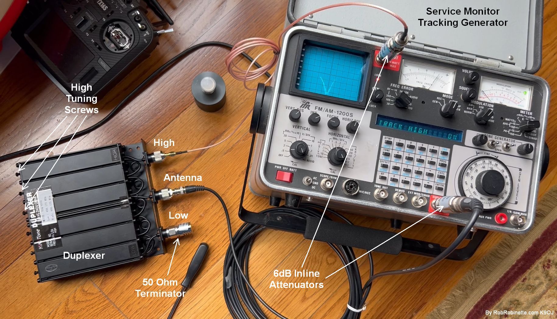
The service monitor's lower DUPLEX BNC connector is the tracking generator output. The upper ANT BNC connector is the spectrum analyzer input. You would connect a spectrum analyzer + tracking generator the same way as shown above. With the notch filter trace showing on the spectrum analyzer display, turn the three High cavity tuning screws to move the three notch traces to the repeater Low frequency. We then stack the three traces for a sharp, deep notch centered on the repeater Low frequency. The two optional inline 6dB attenuators shown above are acting as 50 ohm pass-through terminators to help keep the duplexer at 50 ohms impedance for more accurate tuning. Watch this short video showing a good duplexer notch filter trace on the 1200S service monitor.
We will use a service monitor or spectrum analyzer + tracking generator to tune the duplexer. The tracking generator supplies a swept radio signal that is sent through the duplexer while the spectrum analyzer shows the amount of RF signal that makes it through the duplexer.
First, set the Low repeater frequency in the service monitor. Then use the spectrum analyzer display to calibrate the display by centering the frequency spike on the display center reticule (this step is not required with modern spectrum analyzers). Zoom in using the HORIZONTAL control for a precise setting.
Next, connect the tracking generator output (DUPLEX BNC) to the duplexer Antenna connector (see photo above). To set the Low frequency notch, we connect to the duplexer High connector to the spectrum analyzer input (ANT BNC). We also need to put a 50ohm terminator on the unused Low duplexer connector (see photo above). I use two optional 6dB inline attenuators at the service monitor (see photo above) to keep the duplexer impedance at 50 ohms for more accurate tuning.
Set the spectrum analyzer bandwidth (HORIZONTAL) to 1MHz/DIV, set VERTICAL to anything other than OFF, and set MODE to DUP. Turn on the tracking generator with, "2ND FUNCT, 5/OPT" and set tracking to LOW, MED or HIGH with the keyboard up/down arrows for best signal trace. You will see one to three filter notches on the spectrum analyzer display.
The RFS/Motorola UHF duplexer I used has six duplexer cavities that need to be adjusted. Three cavities for transmit, and three for receive. Adjust the three High cavity tuning screws to stack the three filter notches together over the repeater Low frequency. At this point we're looking to make the notch as deep and sharp as possible, centered on the repeater Low frequency. Reduce spectrum analyzer bandwidth to 10kHz for final tweaking. Lock down the cavity screw lock nuts and verify the notch still looks good.
Move the spectrum analyzer connection from the duplexer High connector to the duplexer Low connector. Move the 50ohm terminator from the duplexer Low connector to the High connector, and repeat the tuning procedure for the repeater High frequency notch.
There are inexpensive Chinese made UHF and VHF duplexers that need a large 10MHz frequency split that will not support standard Ham repeater frequency splits, such as 0.6MHz VHF and 5MHz UHF. Be wary of them because you will not get enough band reject to run standard Ham repeater frequencies at anything over 5 watts. You can use them for non-standard 10MHz repeater splits but those repeaters tend to be used less than repeaters with standard splits.
Chinese Duplexer Spectrum Analyzer Graph
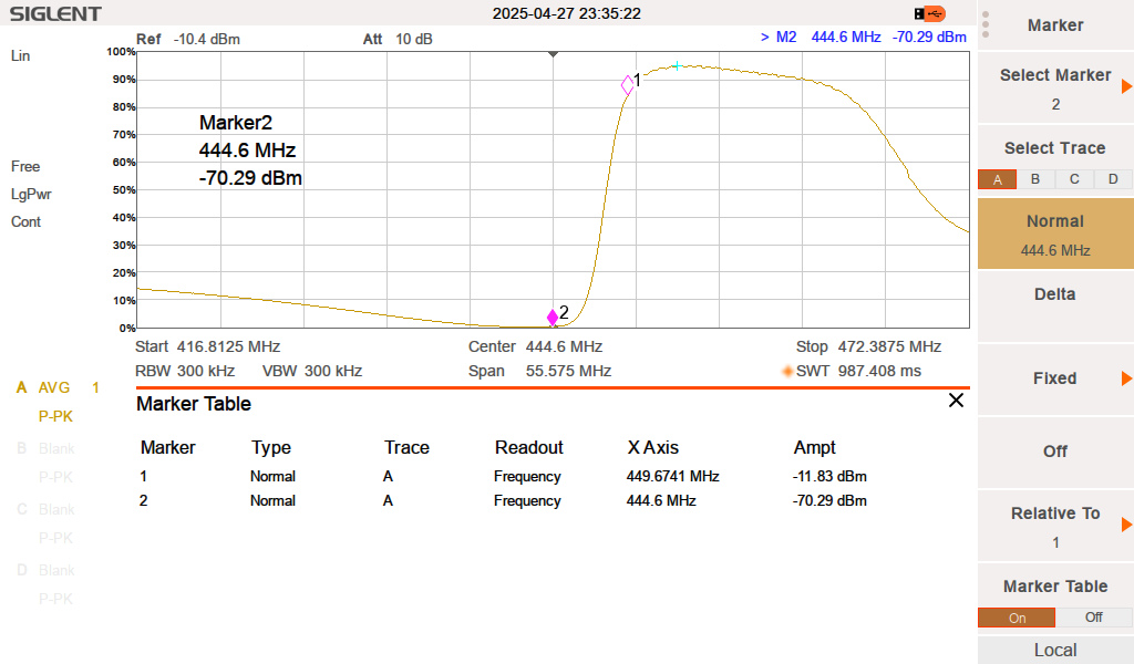
This $90 Chinese Fumei SGQ-450A duplexer is spec'd for 450-470MHz, 50 watts, and 5MHz spacing. Repeater transmit frequency of 444.6MHz is at Marker 2, receive frequency is 449.6 at Marker 1 (standard 5MHz split). You can see the receive frequency (Marker 1) is "down the slope" and showing more attenuation than wanted. A larger split of 9MHz would move the receive frequency to the right, near the small green cross, for minimum attenuation. This duplexer should be spec'd at 10MHz minimum frequency split. Screen capture from Siglent SVA1032X spectrum analyzer.
For more info on tuning duplexers and how they work, see my duplexer page.
The total cost of the repeater was approximately $970 using the components listed above.
After getting the repeater on the air, I submitted repeater info to repeaterbook.com and UnifiedRadios.com.
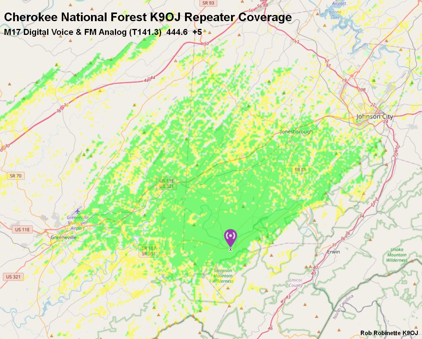
Repeater is located in the Cherokee National Forest in East Tennessee about 15 miles southwest of Johnson City, TN. Map created at Radio Mobile. For the Radio Mobile receiver settings I used .39uv receive, 1.4 meter high antenna and 0db for antenna gain to approximate a handheld radio.
POCSAG Quick Start Guide
POCSAG is a one-way pager protocol that is carried by DAPNET (Decentralized Amateur Paging Network) which was developed by German Amateurs. You can configure your WPSD or Pi-Star hotspot to transmit these messages on the worldwide POCSAG frequency of 439.9875 MHz (or any other frequency you choose). See the DAPNET wiki for a basic overview of POCSAG. POCSAG is an acronym for Post Office Code Standardization Advisory Group which developed the pager code for the British Post Office.
Your hotspot will transmit POCSAG messages on a POCSAG frequency then change back to your regular hotspot frequency. If the hotspot is busy with another mode, POCSAG messages will be stored until the other mode's hang time ends and then the stored messages will be transmitted.
To get your hotspot ready to transmit POCSAG you start with a request for a new DAPNET Account: Open a support ticket and request a new account with RIC (pager ID) at: https://support.hampager.de/index.php The RIC code (capcode) will be your pager "address", similar to your DMR ID.
Sign in with the new DAPNET account then open another support ticket and request a new transmitter. You will receive an email with your transmitter's node callsign (usually your call sign) and a transmitter authorization key.
Pi-Star POCSAG Setup
On main Configuration page enable POCSAG mode and click "Apply Changes".
Main Configuration
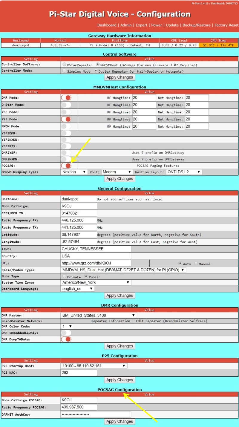
Enable POCSAG mode in "MMDVMHost Configuration", click "Apply Changes", fill in the "POCSAG Configuration" section near the bottom of the page and click "Apply Changes" again.
Then set the POCSAG Configuration (near bottom of page)
Node Callsign POCSAG: what you registered it as, usually your callsign
Radio Frequency POCSAG: 439.987.500 (worldwide standard)
DAPNET AuthKey: Your transmitter's authorization key assigned by DAPNET
Click "Apply Changes"
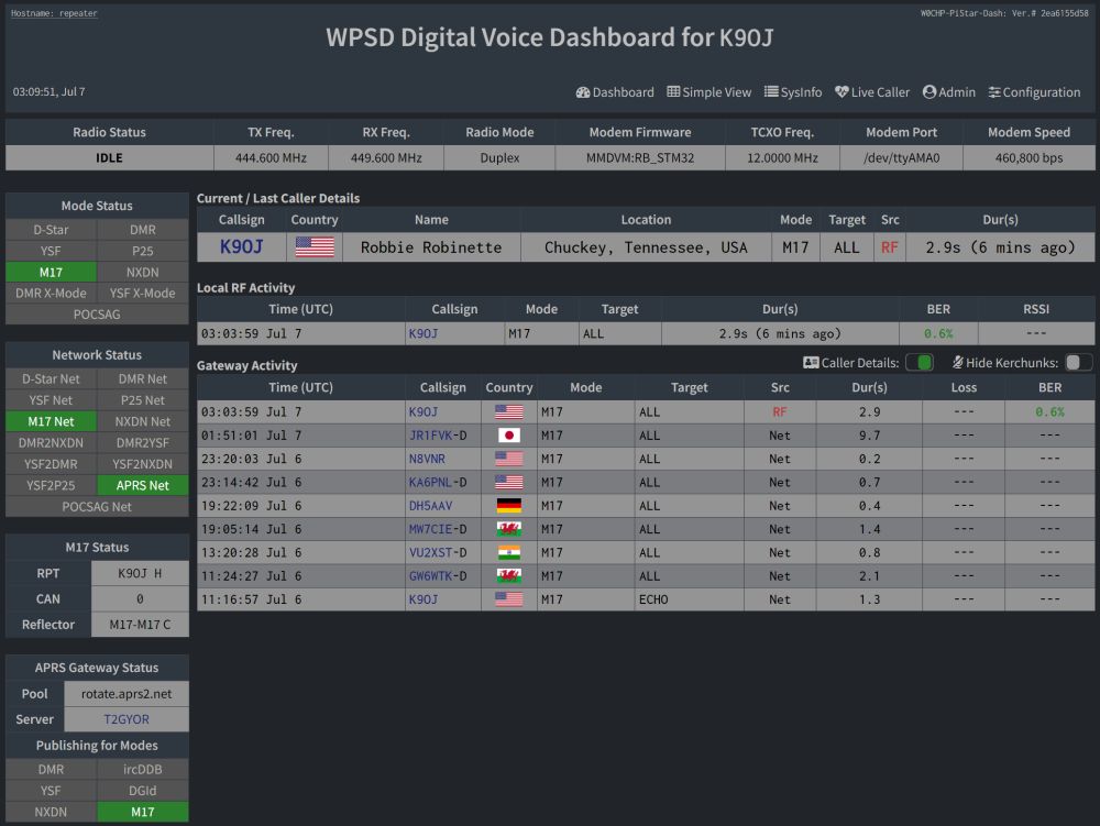
The latest POCSAG activity will show on the WPSD/Pi-Star dashboard. POCSAG activity can also be seen on the "Live Logs" page.
We can use the Android DAPNET app to send messages. DAPNET limits the page to 80 characters.
We can send POCSAG messages by using a DMR SMS message. Send an SMS message to Private DMR Contact 262994 in this format: callsign "space" message text.
We can use the Pi-Star SSH command line to send POCSAG messages:
First you must put your DAPNET website (hampager.de) user name and password in the DAPNET API section found at Configuration/Expert/DAPNET API. Enter your TXAREA, for the USA use: us-all. Click "Apply Changes".
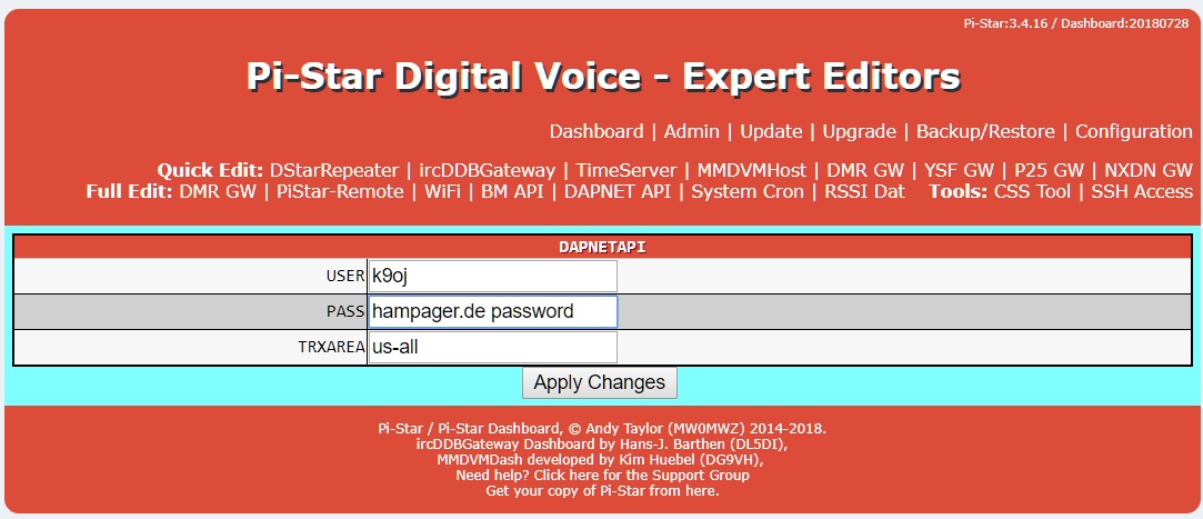
USER and PASS are your hampager.de login credentials (not your transmitter callsign and Authkey). TXAREA for the USA is "us-all".
Then issue this command (with your target callsign and message) at the SSH Access command line: sudo pistar-dapnetapi K9OJ "This is a test message, please ignore"
To get to the SSH Access command line select Configuration/Expert/SSH Access and sign in using the pi-star hotspot username and password.
POCSAG Pagers
We can use a pager to receive POCSAG pages but the pager must be POCSAG capable (most are) and programmable to use 439.9875 MHz. You must also set your capcode (Channel Access Protocol code) or RIC (Receiver Identification Code) which functions as the pager ID. Pager sellers use the term "capcode" for the pager ID and may not understand the term RIC (capcode = RIC). DAPNET POCSAG messages are 1200 baud.
I purchased a new Chinese SingCall W09N pager on ebay for $95 delivered with 3-day shipping (yes, 3-day shipping from China to the East Coast USA). It is an Alphapoc 602R X4 clone. Just tell the seller, witoptech, the POCSAG frequency and your capcode (RIC) and she will pre-program it for you and all you'll have to do is add a AAA battery and you're good to go. The pager is hand programmable for RIC, freq and baud. I'm very happy with the pager. Here's the W09N (GP2009N) User Manual and the W09N Programming Software which allows you to set the frequency and up to eight RIC codes.

This is the Chinese SingCall W09N (GP2009N) pager I use.
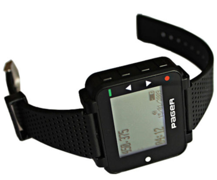
This is the GP2009W watch version.
Hand Programming the Alphapoc 602R, W09N, GP2009N and Ganray Pagers
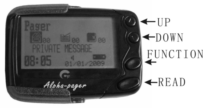
1. Turn pager on
2. Hold the Up and Read buttons down for about 3 seconds until the password is shown.
3. The default password is 0000, press the Down key to move right until the RIC (capcode) page is shown.
4. Press the Function key to change [OFF] to [ON]
5. Press the Down key to move through the characters, press the Function key to change the values.
6. As you continue to the end of the RIC page you'll move on to the next page with BAUDRATE: 1200, POLARITY: NORMAL, FREQ: xxx.xxxx M and PROGRAM EXIT
7. Change the frequency by using the Down key to move between characters and use the Function key to change the numbers.
8. Move to PROGRAM and hit the Function key to save the changes.
9. If you do not want to save the changes move to EXIT and hit the Function key.
Pagers Confirmed to Work With DAPNET
The following pagers have been confirmed to work on the Amateur POCSAG system and worldwide frequency. Most have several models that cover different frequency ranges. You must verify with the seller that the pager can operate in the 70cm Ham band. Be aware that some pagers can only do FLEX protocol and will not receive POCSAG:
Apollo AL-A29 - Must verify the frequency range overlaps the Ham UHF band (most don't).
Apollo 924 UHF 430-450 MHz
Apollo ALA25 T60 (Gold) R8 GP - lowest usable frequency is around 442 MHz so no good for the 439MHz POCSAG frequency
Alphapoc 601, 602R X4 - frequency and RIC can be hand programmed (see above), proprietary USB cable is required to program via free software
SingCall W09N - frequency and RIC can be hand programmed (see above), proprietary USB cable is required to program via free software
Ganray (Chinese AlphaPoc 602 clone) - rebranded SingCall W09N, frequency and RIC can be hand programmed (see above), proprietary USB cable is required to program via free software
GP2009N pager and GP2009W wristwatch - rebranded SingCall W09N, frequency and RIC can be hand programmed (see above), proprietary USB cable is required to program via free software
Daviscomms BR800, BR802 - verify it can be set to Ham band, most cannot
NEC 21/A Skyper - POCSAG compatible but not hand programmable
Many used commercial pagers can be used for Amateur POCSAG but be careful when purchasing. Verify it is compatible with POCSAG protocol (not just FLEX) and the frequency, Baud and capcode can be set before you spend your money. Many old pagers cannot do 449 MHz. Some allow the frequency and capcode (RIC) to be set by hand, others require a programming cable and software. Many sellers will set the frequency and capcode for you.
It has been reported the Alphapoc 602, GP2009N, GP2009W and Ganray pagers use the same programming cable and software.
Using an SDR + VB Cable + PDW to Decode POCSAG Messages
If you have an SDR (software defined radio) you can use VB Cable (donationware) to send the SDR audio to PDW (POCSAG decoding freeware) to decode POCSAG messages.
In your SDR software select VB Cable as your audio output to send the SDR audio to VB Cable.
In PDW select "Interface" then "Setup" and click on "Soundcard", Configuration: "Custom", Sample Rate: "44100", and Soundcard: "CABLE Output (VB-Audio Virtual)". You normally don't need to tweak any of the "Set-Custom" settings but adjusting them may help increase the decode percentage.
SDR + VB Cable Feeding PDW
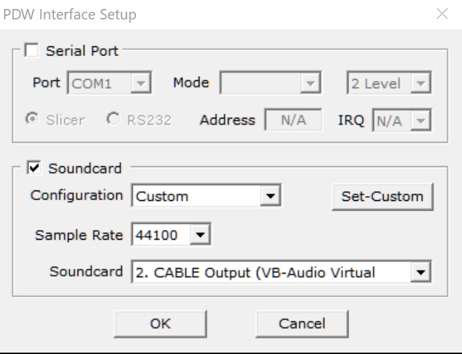
Select Interface/Setup/Soundcard
We can set a filter in PDW to do certain things when a POCSAG message comes in that matches your RIC. The message will show in the lower filter window, an alert sound will play and we can even send an email.
My RIC Filter
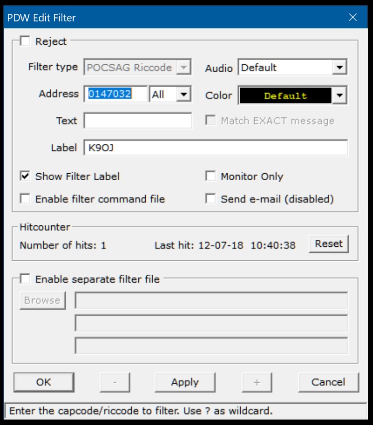
Select Filters/Filter List/Add (Add is at the Filter window bottom left). This filter sends messages addressed to me to the lower PDW Filter Window and plays a sound to let me know I received a message. "Address" is your RIC code.
My Jumbo Spot Pi-Star Settings for D-STAR and DMR
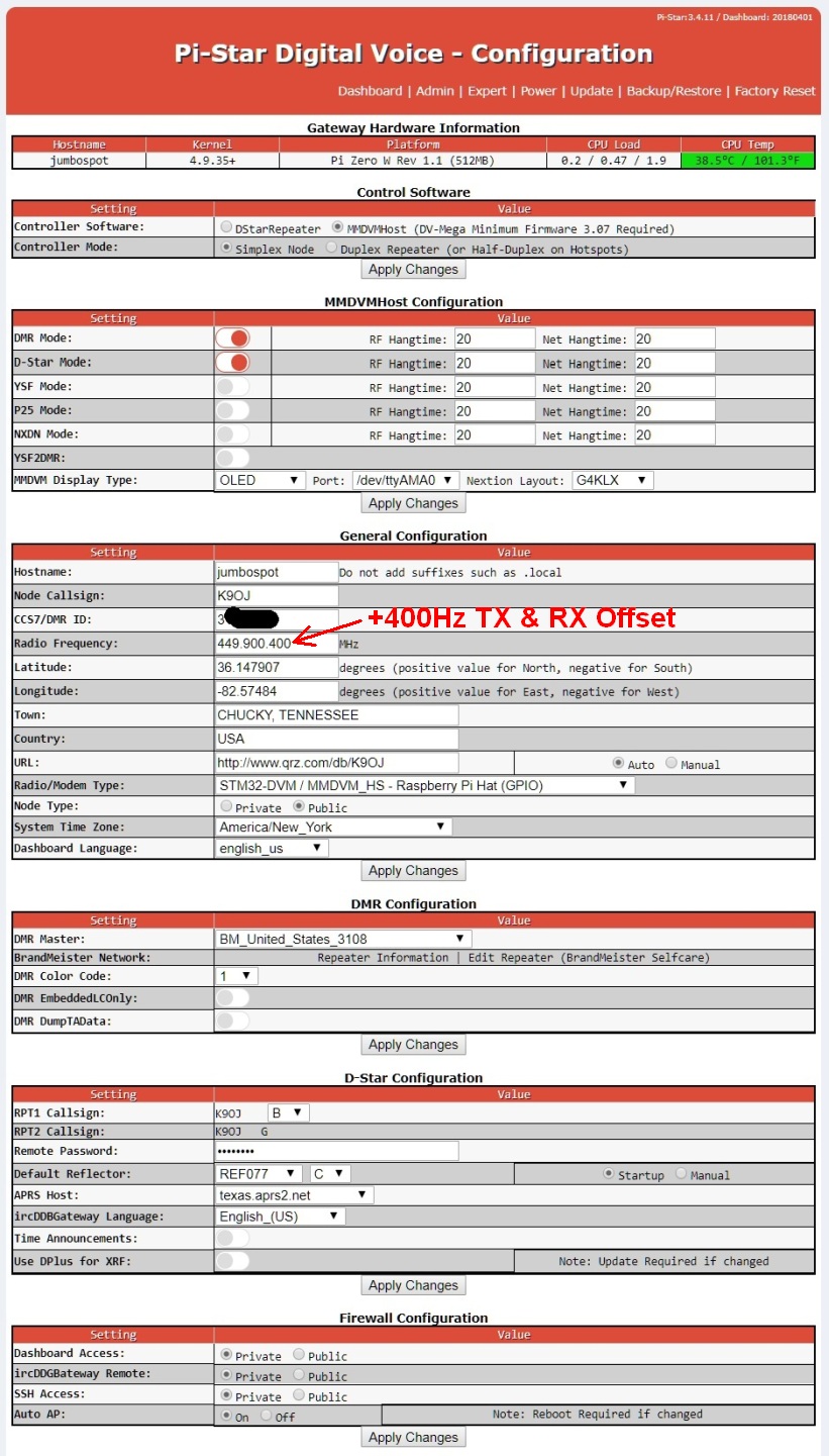
My Jumbo Spot liked a TX & RX offset of +400 but I no longer recommend adjusting the frequency for offset as shown above. I now set the TXOffset and RXOffset to adjust offset.
I'm very impressed with my $26 Jumbo Spot from aliexpress.com. I have ordered many things from aliexpress and haven't had any problems. "RTQ" stand for "ready to QSO" because it comes fully assembled with a case, Pi Zero W, MMDVM_HS_HAT board, antenna, OLED display and Pi-Star loaded 8GB MicroSD Card. You will have to supply a 2.5ma or higher rated power supply with a standard Android phone style micro USB plug. You can just plug it in and it will come up in "Auto AP" mode. Look for a "Pi-Star" Wi-Fi source on your computer and join it, sign in with a password of "raspberry". You can then use a browser to edit the Pi-Star Wi-Fi settings then reboot and the Jumbo Spot should join your Wi-Fi net.
The Jumbo Spot does everything Pi-Star can dish out: Yaesu System Fusion, D-STAR, DMR, P25, NXDN and all the cross modes. It took about three weeks for delivery from China but I had to wait longer than that for my American assembled Nano-Spot. Although The Jumbo Spot's computer is a Pi Zero W it performs really well and uses standard raspberry pi Linux and MMDVM_HS_HAT modem for easy kernel, operating system and MMDVM firmware upgrades. The radio chip is rated at 20 milliwatts of output power (.02 watt).
Jumbo Spots typically use a 500Hz TX and RX offset. I played around with it and found 400Hz was best for my Jumbo Spot and radios. I'm currently running YSF, D-STAR, P25 and POCSAG on my Jumbo Spot and DMR on the Dual Spot (dual radio). The dual radio with DMR can enable both time slots.
Some Chinese hotspot users have reported that after upgrading the MMDVM modem board firmware their hotspots have quit working. They had to adjust their RXOffset and TXOffset to get the hotspot working again. Some have reported having to use offsets as large as 4000! (4kHz). I believe this is happening due to the Chinese manufacturers putting custom offsets into the modem firmware which is lost when the firmware is updated. They may be doing this to keep us from realizing how imprecise their TCXOs are. If this happens to you after a firmware upgrade follow the BER Tuning Guide to get your hotspot up and running again.
To update the Jumbo Spot MMDVM Modem firmware at the Configuration/Expert/SSH cursor:
sudo
pistar-mmdvmhshatflash hs_hat (Most modems run 14.7456MHz TCXO)
sudo pistar-mmdvmhshatflash
hs_hat-12mhz (12.288MHz TCXO)
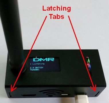
To open the case you remove the antenna then pry apart the upper cover enough to get the tabs clear and pull it off.
MMDVM_HS_HAT_DUPLEX Pi-Star Settings For YSF, D-STAR, DMR and P25
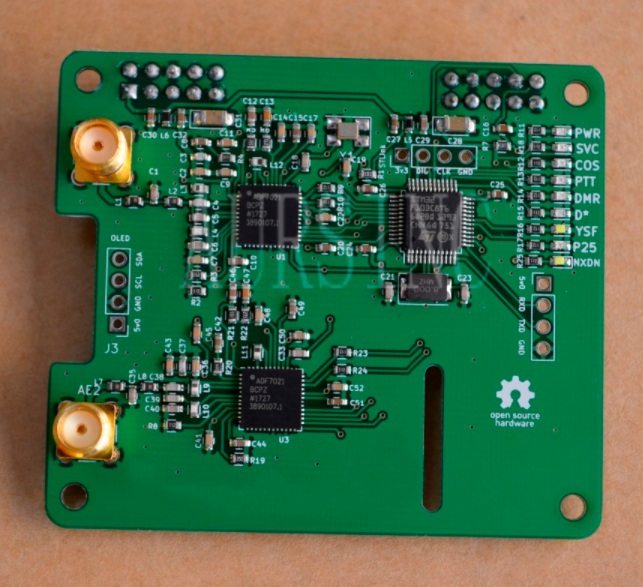
Generic Chinese MMDVM_HS_HAT_DUPLEX Radio/Modem
Dual UHF radios, MMDVM, OLED, Nextion and STLink solder pads.
I purchased this $28 generic Chinese MMDVM_HS_HAT_DUPLEX Radio/Modem from aliexpress.com and paired it with a raspberry pi2 and it works great. It came with MMDVM 1.3.3 firmware installed and it's been upgraded to 1.6.1 (as of 2024). This dual-radio MMDVM_HS_HAT_DUPLEX radio/modem can act as a repeater and transmit on the output frequency simultaneously what it receives on the input frequency. It will also allow you to use both DMR timeslots simultaneously. The two radio chips on the board are rated at 20 milliwatts each.
My board came with two UHF antennas and two female SMA antenna connectors that I had to solder to the board. The female pi hat connectors came soldered in place. The board also came with two sets of male jumpers that can be used on boards like the pi Zero that come with no 40 pin hat connectors. My pi 2, like the pi 3, has the male 40 pin connector already in place so I didn't have to use the jumpers but it's nice that they include them.
This board fits on top of a pi2, 3, 4, 5, pi Zero, pi Zero W or pi Zero W 2 but not a pi1. Just press the board in place, install Pi-Star and you're ready to go.
Be sure and separate your RX and TX frequencies by at least 5MHz to reduce interference between the transmitter and receiver.
One major difference with a dual radio board like this compared to a simplex hotspot is you have to program the correct DMR time slot when programming your radio's code plug. A simplex board will send both timeslots' transmissions using a single timeslot but this board will send TS1 input out TS1, and TS2 input out TS2. It took me a while to figure out why I wasn't hearing any DMR traffic because my MD-380 radio was monitoring the wrong time slot.
The MMDVM_HS_HAT_DUPLEX worked fine out of the box on YSM, D-STAR and P25.
Some Chinese hotspot users have reported that after upgrading the MMDVM modem board firmware their hotspots have quit working. They had to adjust their RXOffset and TXOffset to get the hotspot working again. Some have reported having to use offsets as large as 4000! (4kHz). I believe this is happening due to the Chinese manufacturers putting custom offsets into the modem firmware which is lost when the firmware is updated. They may be doing this to keep us from realizing how imprecise their TCXOs are. If this happens to you after a firmware upgrade follow the BER Tuning Guide to get your hotspot up and running again.
To update the DUPLEX_HAT MMDVM Modem firmware at the Configuration/Expert/SSH cursor:
sudo pistar-mmdvmhshatflash hs_dual_hat
(14.7456MHz TCXO, this is the usual frequency)
sudo pistar-mmdvmhshatflash hs_dual_hat-12mhz (12.288MHz TCXO)
A $6 OLED screen can be easily added to this MMDVM_HS_HAT_DUPLEX board. I added a Nextion display to the board.
I installed 90 degree SMA connectors so I could point the two antennas away from one another (see photo below). This exploits the signal null of the transmitting antenna to reduce interference between the transmitter and receiver.
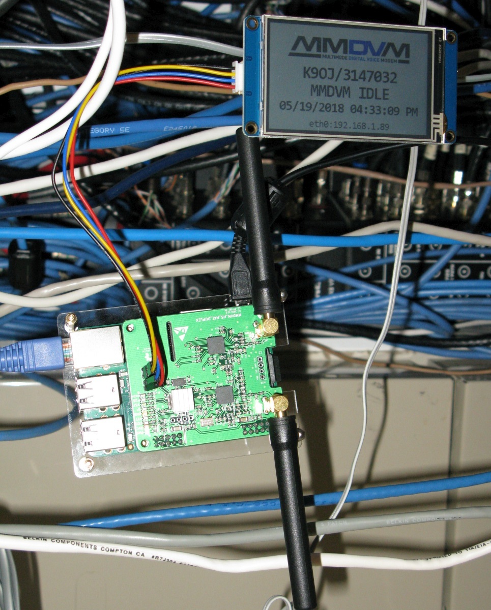
Antennas vertical and pointed in opposite directions to minimize interference. Shown here during Nextion display testing.
Modem Firmware Updating
The easy way to update MMDVM modem firmware is to use the WPSD dashboard. The modem update command is at Admin/Advanced/Tools. You can also use these command line commands to update various boards' modem firmware. Note the two TCXO frequencies for the HS and DUAL_HAT modems. Pi-Star shows the TCXO frequency of your modem on the Admin page. If you flash the wrong TCXO firmware you'll need a huge RX and TXOffset to make the modem work so simply re-flash using the correct TCXO frequency.
MMDVM_HS_Hat board (14.7456MHz TCXO, this is the usual frequency)
pi-star:
sudo pistar-mmdvmhshatflash hs_hat
wpsd: sudo wpsd-modemupgrade hs_hat
MMDVM_HS_Hat board (12.288MHz TCXO)
pi-star:
sudo pistar-mmdvmhshatflash hs_hat-12mhz
wpsd: sudo wpsd-modemupgrade hs_hat-12mhz
HS_DUAL_HAT board (14.7456MHz
TCXO)
pi-star:
sudo pistar-mmdvmhshatflash hs_dual_hat
wpsd: sudo wpsd-modemupgrade hs_dual_hat
HS_DUAL_HAT board (12.288MHz
TCXO)
pi-star:
sudo pistar-mmdvmhshatflash hs_dual_hat-12mhz
wpsd: sudo wpsd-modemupgrade hs_dual_hat-12mhz
Nano hotSPOT board
sudo pistar-nanohsflash nano_hs
NanoDV NPi board
sudo pistar-nanodvflash pi
NanoDV USB board
sudo pistar-nanodvflash usb
ZUMspot RPi board
sudo pistar-zumspotflash rpi
ZUMSpot duplex board conected to
GPIO
sudo pistar-zumspotflash rpi_duplex
ZUMspot USB dongle
sudo pistar-zumspotflash usb
ZUMspot Libre Kit or generic MMDVM_HS
board with USB
sudo pistar-zumspotflash libre
Tuning Your Hotspot's BER
Many hotspots require the transmit and receive frequencies to be adjusted for best reception. Pi-Star's Dashboard "Local RF Activity BER" (bit error rate) displays your hotspot's reception error rate. We can minimize the BER by adjusting Pi-Star's Configuration/Expert/MMDVMHost/Modem/RXOffset setting. RXOffset adjusts the hotspot's receive frequency in Hertz. It can be a negative or positive value. Many MMDVM boards come with a sticker that lists a starting RXOffset & TXOffset settings. Use the sticker setting as the starting RX and TXOffset values.
If you have an SDR waterfall display or a frequency counter you can use it to monitor your hotspot transmission to see where it is actually transmitting. Adjust the Configuration/Expert/MMDVMHost/Modem/TXOffset setting so that your hotspot is transmitting exactly on frequency. Then set the RXOffset to the same value. This is typically a very good starting point for BER fine tuning.
RXOffset adjusts the hotspot's receive frequency in Hz. It can compensate for an out-of-alignment hotspot receiver or an out-of-alignment radio transmitter--you can set your hotspot receive frequency to exactly match your radio's transmit frequency. RXOffset affects the BER (reception Bit Error Rate) shown on the Pi-Star Dashboard.
TXOffset adjusts the hotspot's transmit frequency in Hz. It can compensate for an out-of-alignment hotspot transmitter or an out-of-alignment radio receiver. TXOffset affects the BER of your radio--not the BER shown on the dashboard. If your radio displays BER you can change TXOffset to tune for lowest radio BER.
Pi-Star Configuration / Expert / MMDVMHost / Modem / RXOffset
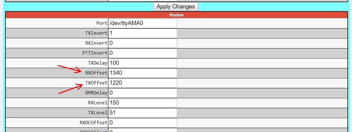
RXOffset of 1340 was set by BER fine tuning, TXOffset was set using an SDR waterfall display. The difference between the two is probably due to my MD-380 DMR radio being slightly out of alignment.
Keep in mind RXOffset and TXOffset are applied to all digital modes so if you use multiple radios and/or modes with your hotspot they will all be affected. You'll have to tune for the best overall signal and BER for all your radios.
If the Dashboard BER is higher than about 1% then I recommend you tune RXOffset to reduce it to a minimum.
An RXOffset of -22 (22Hz shift down) on my Nano-Spot worked best for my radios but one Nano-Spot user had to use a setting of 1200 to get his MD-380 to decode DMR from his hotspot. Most likely his MD-380 receiver is way out of alignment.
The Chinese Jumbo Spot comes with a sticker that shows the TXOffset and RXOffset need to be set at 500 (+500Hz) right off the bat. After fine tuning I ended up with 400 for both RX and TXOffset.
My generic Chinese MMDVM_HS_HAT_DUPLEX board works best with an RXOffset of 1340 and TXOffset of 1220.
Hotspot Can't Receive DMR Transmission
This is a fairly common problem with a new hotspot. If your RXOffset is far enough off the hotspot will not decode your radio's DMR signal. Look for a sticker on the modem board or documentation that gives a starting TX and RXOffset. If you can't find one then just start adjusting RXOffset in steps of 100. Try 100, -100, 200, -200, 300, -300, 400, -400 . . ." until your hotspot begins to decode the digital signal and it shows up on the Pi-Star Dashboard. Then set your TXOffset to match. I like to use an SDR waterfall display to adjust the TXOffset so the hotspot transmits exactly on the set frequency. See the next section for more info on RXOffset and BER tuning.
BER Fine Tuning
Note: Most new generic Chinese modem boards now work right out of the box with a BER of less than 1% without adjusting the TX or RX offsets.
DMR seems to be more sensitive to frequency and BER so I like to use it when tuning the BER. If you don't use DMR then just use the digital radio you use most with your hotspot.
Set your radio to its lowest power setting to make your hotspot more sensitive to RXOffset adjustments.
Note that RXOffset and TXOffset affect all hotspot modes, not just DMR.
I like to use two browser windows to speed BER tuning. One window is open to the Configuration/Expert/MMDVMHost page and one is open to the Dashboard page showing BER.
Set your radio to the parrot channel if available (DMR private call to talk group 9990) and transmit for at least 10 seconds to get a BER calculation. You should always give your callsign when transmitting, "K9OJ echo test".
Monitor the Dashboard BER. I like to write it down when testing. Transmit two or three times to make sure you're getting a representative BER value. Be sure and transmit with the radio held in the exact same position to make the BER values consistent.
Start by using an RXOffset increment of 100. Set the RXOffset setting to 100 (or add 100 to a previously set value) and transmit three times and note the BER. If BER increased then try going negative with an RXOffset setting of -100.
If nothing much changes try again with another step of 100.
As you're changing the RXOffset you'll find the BER starts to decrease and then increase when you go too far. When that happens back up using smaller steps of 20, then 10, then 1s until you find the minimum BER. You should shoot for something under 1%.
The last time I tuned a hotspot BER my RXOffset went like this:
100 BER 1.7%, 200 1.7%, 300 1.1%, 400 0.3%, 500 1.3%, 450 0.7%, 425 0.5%, 400 0.2%, 350, 0.6%, 375 0.5%, 385 0.5%, 395 0.3%, 397 0.3%, 410 0.4%, 405 0.3%, 402 0.3% and 400 was consistently lowest.
Now check your other radios and verify their BER is reasonable. If not then tune the BER using that radio and then split the difference between the other radios for the best average BER.
Ham VHF and UHF Digital Modes Modulation Video
How the digital modes look and sound on a waterfall display. YSF & P25 sound like white-noise static. DMR and M17 sound like digital static and D-STAR sounds like a "typical digital" signal. In the video DMR section there are two transmissions, the first is my handi-talkie and the second is the hotspot echoing my transmission. The hotspot's 1.2kHz transmission start tone and DMR "choppiness" were an artifact of the MMDVM firmware which has been fixed.
Adding An OLED Display To A Hotspot
I recommend buying your hotspot with an OLED already installed but it's pretty simple to add a .96 or 1.3 inch OLED display to your MMDVM modem board so you can track activity and callsigns. You connect the display to the modem then set Pi-Star's display settings.
I purchased a generic Chinese .96 inch OLED display from aliexpress.com for $3. There are two pin standards for OLED displays. If you get the correct pin out then you can use a simple 4-pin header to connect the display. Get the wrong pin out and you'll have to use wire jumpers. You want the pin out that matches your hotspot. You can see my board below needed the 5v pin on the outside ( 5v ground SCL SDA)
You can connect the display to either the modem card or the raspberry pi but since most modem cards use the raspberry pi's GPIO pins it's easiest to connect the display directly to the modem card.
I had to solder a 4-pin header into my MMDVM_HS_HAT_DUPLEX modem's OLED display solder pads. This allowed the use of the included push-on wire bundle to connect the display to the modem board.
4-Pin Header
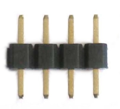
Connect the OLED display wires to your MMDVM modem card like this:
Red to 5vO or 3vO (5 or 3.3 volts Out)
Black to GND (ground)
Purple to SCL
Orange to SDA
Only these four connections are necessary.
MMDVM Modem Board's OLED Connector
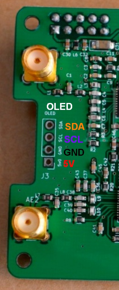
Solder a 4-pin header to the OLED solder pads and connect the display. Only these four connections are necessary. Note my modem board has 5v on the outside pin. Some OLED displays have the GND on the outside pin. Try to get the correct OLED pin out to match your modem board so you can solder directly to a 4-pin header.
With many modem boards you can solder the OLED display pins directly to the modem board OLED solder pads. Be sure and verify the pins line up correctly. My Chinese OLED pins didn't line up with the modem board's OLED solder pads so I had to use a header and wires to connect the display. I don't know if it was the OLED or my modem board that was nonstandard but the GND and 5V connections were swapped and didn't allow a direct connection.
If your modem board is a ZUMspot or clone you will need to use the Pi's GPIO pins to feed the OLED display.
ZUMspot GPIO: Pin 1 = VCC, Pin 3 = SDA, Pin 5 = SCL, Pin 9 = GND
In Pi-Star's main configuration page select the following settings:
Pi-Star Display Settings For OLED Display

Select "MMDVM Display Type: OLED Type 3 (.96") or OLED Type 6 (1.3")" and "Port: Modem".
If you connect your OLED display to your MMDVM modem card (not to the raspberry pi) then you must select "Modem" for the "Port:" setting.
If you connect your OLED display to the raspberry pi GPIO pins then you must select "ttyAMA0" for the "Port:" setting.
With these settings the display should now show callsigns and operating info.
Adding A Nextion Display To A Hotspot
Nextion displays come in larger sizes than OLED and they are customizable using the free Nextion Editor to create your own custom .tft screen configuration layout files.
Note that you are not required to use the Nextion Editor, there are ready-to-go .tft files you can load into your display to get you up and running quickly.
It's pretty simple to add a Nextion display to your MMDVM modem board. You connect the display to the modem, load a .tft display config file using a MicroSD card and then set Pi-Star's display settings.
I added a 3.2 inch Nextion display to my MMDVM_HS_HAT_DUPLEX modem card + Pi2 hotspot. I purchased the NX4024T032 Nextion display on Amazon for $34.
My Nextion display included a small MicroUSB board that's used for testing the display. You can connect the display's black and red power wires to the MicroUSB board to power it up and test it before connecting it to a modem. The MicroUSB board is not needed for use with the hotspot.
You can connect the display to either the modem card or the raspberry pi but since most modem cards use the raspberry pi's GPIO pins it's easiest to connect the display directly to the modem card.
I had to solder a 4-pin header into my MMDVM_HS_HAT_DUPLEX modem's Nextion display solder pads. This allows connection using the display's push-on wire connectors.
4-Pin Header
Connect the Nextion display wires to your modem card like this:
Red to 5vO (5 volts Out)
Blue to RXD (receive data) Note: connect TXD on the Nextion display to RXD on the modem board.
Yellow to TXD (transmit data) Note: connect RXD on the Nextion display to TXD on the modem board.
Black to GND (ground)
MMDVM_HS_HAT_DUPLEX Nextion, OLED and STLink Solder Pads
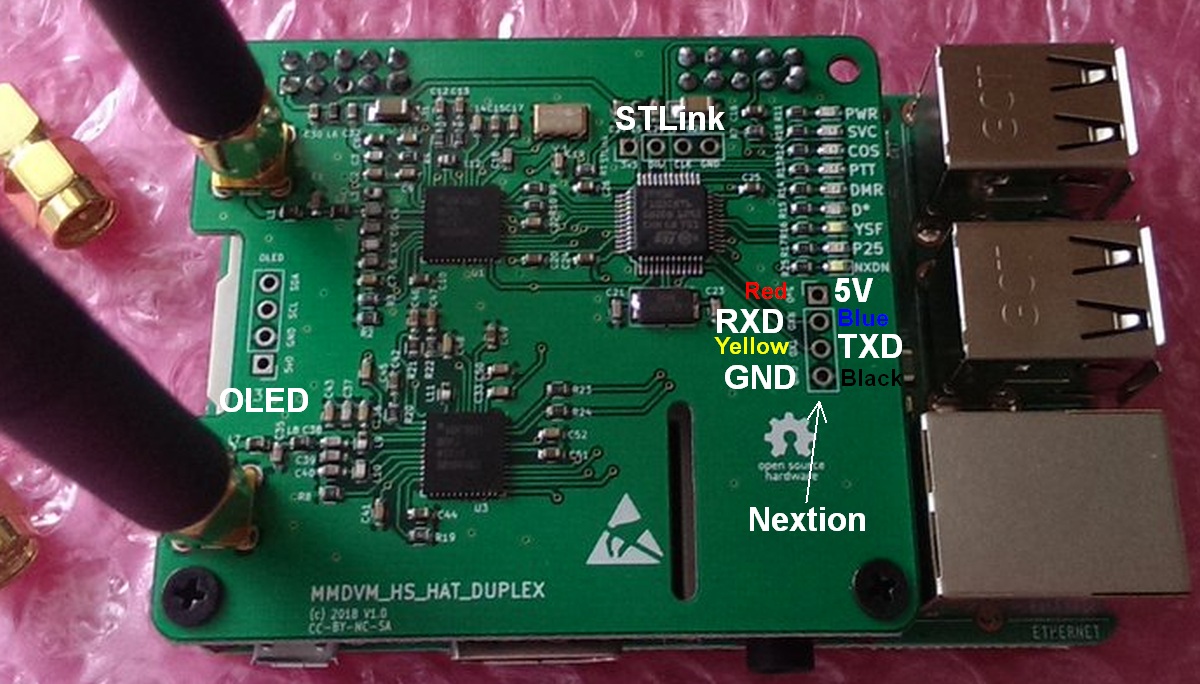
I soldered a 4 pin header to the Nextion solder pads to allow the use of the Nextion display's push-on connectors. Note the OLED solder pads at left between the antennas and the STLink pads at top center. The STLink pads are used for flashing firmware.
Testing the Nextion display.
I used the NX4823T032-L2.tft file from the MMDVMHost github website to configure my 3.2 inch Nextion display. Note the "32" in the file name means 3.2 inch display. Be sure and download the file that matches your screen size. This file uses the ON7LDS layout which displays the hotspot's IP address.
You also have the option of downloading the free Nextion Editor to create your own custom .tft screen configuration files.
To get the .tft file into the Nextion display you need to use a MicroSD card formatted in FAT32 with the .tft file as the only file on the card.
Power down and insert the MicroSD card with the .tft file into the Nextion display's MicroSD card slot located on the back of the display (not the raspberry pi's SD card slot).
Upon power up the Nextion display will load the .tft file and configure itself. The Nextion screen will display the status of the .tft update. On my first try I got a "model mismatch" error because I used a .tft file for a 3.5 inch display, not a 3.2 inch like I needed. Once the update is complete you can power down and remove the MicroSD card.
In Pi-Star's main configuration page select the following settings:
Pi-Star Display Settings For Nextion Display
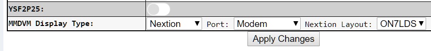
Select "MMDVM Display Type: Nextion", "Port: Modem" if you connect the Nextion display to the MMDVM modem board and I used an ON7LDS .tft file so I selected "Nextion Layout: ON7LDS". "Nextion Layout" needs to match the layout of the .tft file.
If you connect your Nextion display to your MMDVM modem card (not to the raspberry pi) then you must select "Modem" for the "Port:" setting.
Raspberry pi GPIO Pinout
If you connect your Nextion display to the raspberry pi GPIO pins then you must select "ttyAMA0" for the "Port:" setting.
Red = 5v+ PIN 2
Black = Ground PIN 6
Yellow = GPIO14 PIN 8
Blue = GPIO15 PIN 10
I selected a tty port by mistake and the hotspot could not transmit and receive due to my setting error.
With these settings the display should now show callsigns and operating info.
Many people use standoffs to mount the screen to the raspberry pi's case. I mounted my display to the bottom of the pi's case.
Open Source Hardware Licensing
There's been a lot of discussion about MMDVM_HS ripping off ZUMspot and Chinese hotspot manufacturers ripping off everyone. The ZUMspot and MMDVM_HS_HAT creators use this Open Source Hardware license. This license is about sharing a design for the benefit of humanity and allows anyone to build the hardware. The creators of ZUMspot and MMDVM_HS_HAT include a non-commercial clause that simply states:
A commercial use is one primarily intended for commercial advantage or monetary compensation.
You would have to prove the guy in China selling these boards is doing it primarily for monetary compensation. He's legal as long as he says his primary purpose is to make this hardware available to as many Hams as possible at a good price. The license doesn't even prevent him from making a profit.
The primary purpose of the Open Source Hardware license is to prevent someone from taking credit for your design, not to restrict the manufacture of the hardware. Proper "China Spots" should have the MMDVM creators' callsigns on the boards to meet the license requirements.
There is no "genuine" ZUMspot or HS_HAT versus a "clone" because they were released as Open Source Hardware. By using the Open Source Hardware license the creators gave approval for anyone to build these boards. With this license there are no clones or pirates.
I appreciate all the hard work that went into creating these MMDVM boards and I love that the creators gave the design away using the Open Source Hardware license so Hams around the world could benefit. If the ZUMspot and MMDVM creators were worried about other people "ripping them off" by building their hardware they should have patented the design. Please don't give away your design and then bitch about someone using it.
I use the Open Source Hardware license without a non-commercial clause for some of my designs because the important thing is to get the hardware to the users.
Modifying Motorola P25 Astro CPS Software To Allow Out-Of-Band (OOB) Frequencies
As I mentioned above I accidentally purchased a UHF Range II (S Split) Motorola XTS3000 P25 radio with band coverage of 450 - 520MHz (outside of the 70cm Ham band). The UHF Range 1 (R Split) radios with band coverage of 403 - 470 MHz are preferred for Ham use but the 450 - 520MHz radios can be programmed down to 440MHz using a modified Astro CPS program. Standard Astro CPS will allow a slight out-of-band programming like I did for my hotspot at 449.900MHz. CPS will let you know you're out of band but it will still allow you to upload it to the radio. If you try to program a frequency too far out of band CPS will display an error message and not upload the code plug to your radio.
I followed the guidance at this website to modify the AstroPort.exe (Saber and XTS3000 Astro CPS) file to allow programming of XTS3000 450 - 520MHz radios to accept frequencies from 440 - 520MHz. This will allow you to program 70cm repeaters in the 440 - 450MHz range. I believe this is a valid modification for Amateur Radio use. Output power will probably be reduced and performance isn't guaranteed when transmitting out-of-band but my radio performs really well.
While I was at it I also modified Astro CPS for Range I (403 - 470MHz) UHF radios to allow 403 - 477MHz frequencies.
You can download Saber and XTS3000 CPS with the modified "AstroPort.exe" file here. After installing the Saber and XTS3000 CPS program simply replace the original "AstroPort.exe" file with the modified file. The modified file and instructions are in the zip file in a folder called "Modded_AstroCPS".
Astro 25 CPS software for the XTS2500 and XTS5000 can also be modded to allow out-of-band frequencies following the guidance at this website.
XTS3000 Housing Swap
I like the look of the firemen yellow Motorola radios so I bought a new Motorola OEM yellow housing for my XTS3000 on eBay and swapped the chassis, control module and "Motorola" placards (front and rear) into the yellow case. The new case includes a new plastic display window so the radio will look new after the swap.
There are many YouTube videos that detail the swap but this one is the best. Referencing this video and the pdf linked to below will get you most of the way through the swap. The chassis swap is easy with the OEM Motorola chassis removal tool (eBay) but getting the control module out can be a pain.
It took me a couple of hours to do the swap because I had trouble getting the knobs and knob inserts off and getting the control module out. I also did a ton of Googling and YouTubing to make sure I was doing it right.
Refer to this excellent pdf for chassis removal and reassembly: Batdude's Guide to the XTS3000 & XTS5000.
You must use the Motorola chassis removal tool to get the chassis out of the old case shell without cracking the case. The tool also aids in reassembly. I got my tool on ebay. Just search for "Motorola XTS3000 chassis tool".
From Old Scratched Up Black Case to New Fireman Yellow
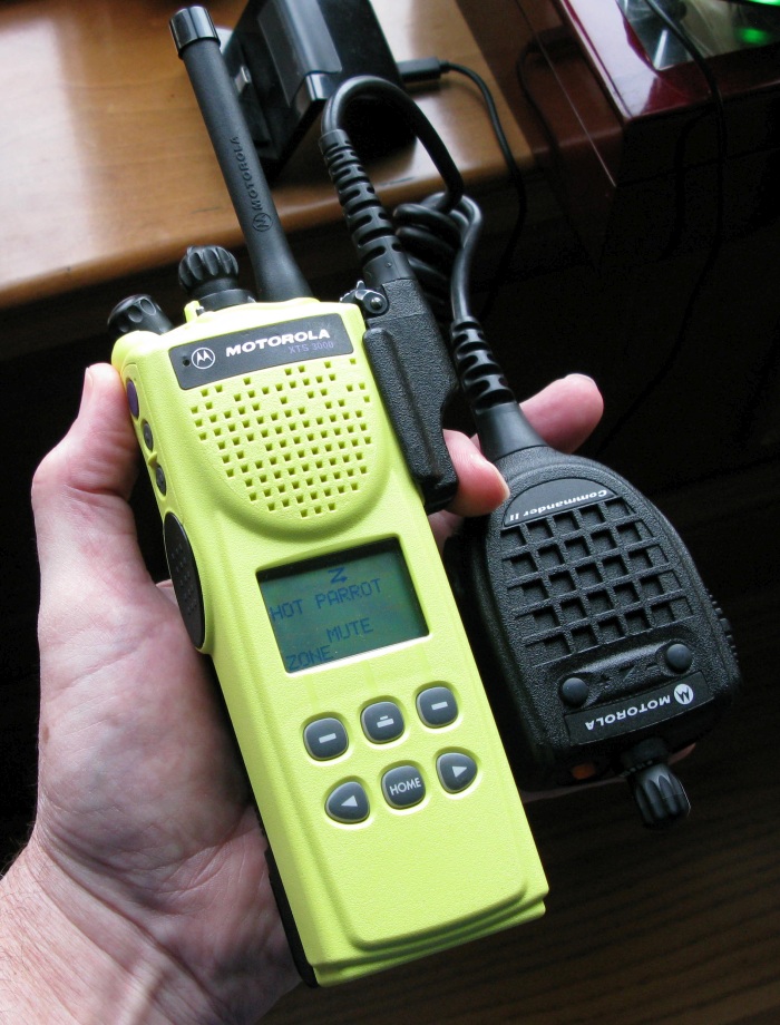
Disassembly
You must release the Flex ribbon connector that connects the control module to the chassis as you remove the chassis from the case.
The trick for removing the knobs is to push up on one side of the knob with both your thumbs on one side of the knob and fingers on the other side to start that side of the knob up, then push up on the other side of the knob to get it to start up. When you get both sides up a little the knob will slide off.
Below the channel selector knob lives a little "light tube" used to illuminate the channel markings. This light tube is clear plastic and very easy to lose. Watch for it as you remove the channel selector knob and knob insert.
Both of my knobs came off and left the knob insert on the control shaft. If the knob insert stays on the knob shaft you need to use a small jeweler's screwdriver to gently push outward on two little tabs that latch onto the control shaft. Looking down into the insert you'll see the two latch tabs. Move the two tabs just a little outward with the screwdriver while pulling up on the insert will get it to slide off. If you damage the inserts they won't latch onto the shaft and the knob won't be secure. Replacement inserts are available but both of mine were undamaged and reusable.
The volume knob insert has an o-ring that may stick inside the insert or may be left on the control shaft. Don't lose it. Remove it from the insert.
When you remove the radio chassis the control module remains in the case. The control module includes the antenna connector and both knob controls. To remove the control module start with removing the single screw that holds the speaker in place and removing the spring bar the screw holds down. Gently slide the two "Flex" ribbons up out of their slots on both sides of the radio to free them. Make sure the speaker is loose so it can move out of the way when the control module comes loose. When looking into the radio case you want to release the control module's top left locking tab. Insert a small, thin flat-blade jeweler's screwdriver between the control module tab (white) and the case and gently pry the tab until it unlatches. In the disassembly/assembly YouTube video the guy struggles to release the right module tab. It's much easier to release the left tab. Releasing the left also makes it much easier to get the control module out.
There is a small hole in the case to help you push out the front "Motorola" placard. I used a thin pick to push the placard out enough to get a fingernail under it. Use gentle pressure to peel it off and it won't warp or bend. The small rear placard came off with the use of just a fingernail. Warming the placards before removal with a hair dryer can make it easier to get them off without damage. A little general purpose glue will hold them in place on the new case.
Reassembly
Be sure and remove the new case's inside viewport protective film and try not to get fingerprints on it or the actual display module. Leave the outside protective film on until the radio is fully reassembled.
Insert the control module and simply push it up and snap it into place. Look at the knob and antenna connectors to make sure the module is fully in place and centered. Inspect both control module locking tabs to make sure they are fully engaged.
Gently slide the two Flex ribbons into their slots on both sides of the case.
Install the speaker holding spring bar into place and screw it down.
Put the volume knob o-ring on the control shaft first, then install the knob inserts and knobs. The control shafts are keyed to line up with knob insert slots. The knobs have indentions that must line up with the shape of the knob insert.
Place the rubber button panel into the new case.
You must make sure the chassis o-ring stays in its groove as you insert the chassis into the new case.
Don't forget to install the speaker screw, install the button pad or to remove the new case's window inside protective film.
Keep the radio display-up when inserting the chassis to keep the display module from falling out of place.
Attach the Flex ribbon to the chassis and gently slide the chassis up into the case as you close it but don't close it all the way.
Use the Motorola chassis removal tool as shown in Batdude's pdf to help snap the chassis fully into the case without damage to the case or o-ring. Carefully inspect the o-ring to make sure it stayed in place.
In the end the swap went well with no damage and no lost or extra parts. The biggest bonus is the radio looks brand-spankin' new with a scratch free display.
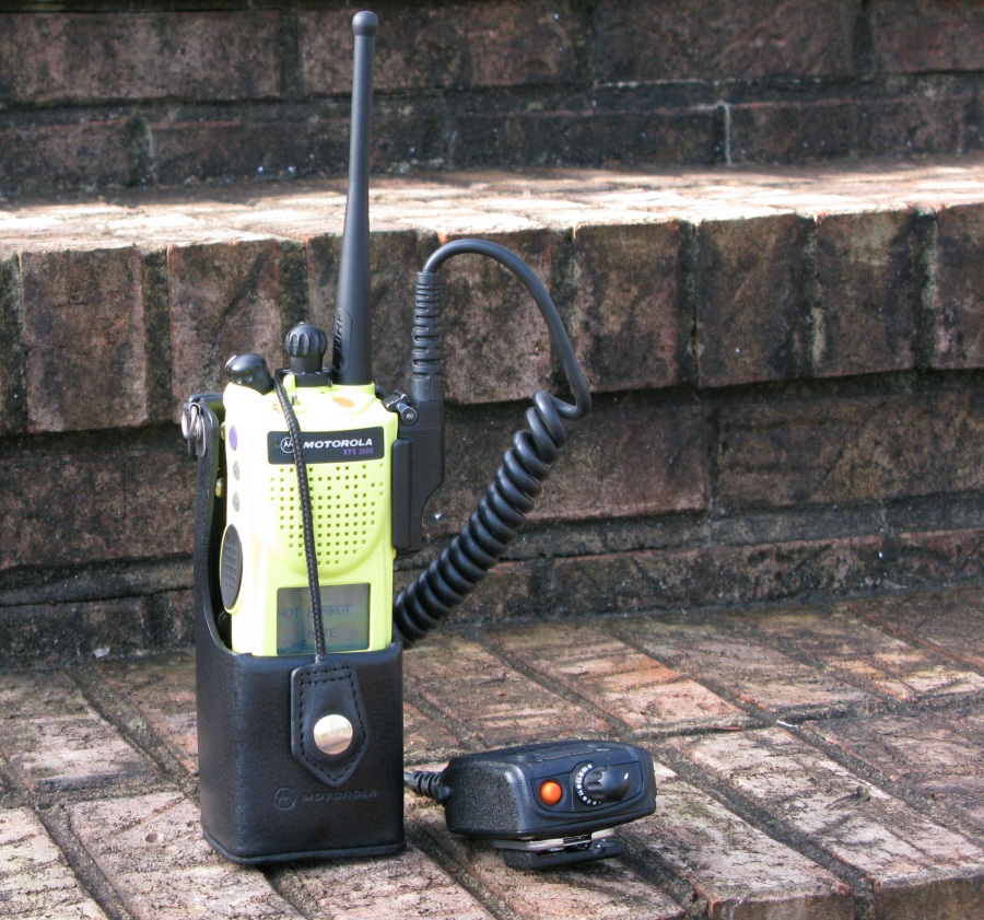
Motorola XTS2500 & XTS5000 Info
I purchased a VHF XTS5000 P25 radio (136 - 174MHz $130), Ribless programming cable ($27) and Astro 25 CPS programming software ($25); all from eBay. The XTS5000 is one generation newer than the XTS3000 but it is very similar. The XTS2500 & XTS5000 use the same batteries and speaker mics as the XTS3000 but the programming cable and CPS software are different. Make sure the programming cable you get specifically mentions the model radio you have. The XTS2500 & XTS5000 use "Astro 25 CPS" programming software.
The XTS2500 and XTS5000 come in the same lineup as the XTS3000. There are Model I (no display or front buttons), Model II (display + 6 buttons) and Model III (display + full keypad). All models come in VHF, 700/800MHz and two UHF versions. Like the XTS3000 UHF Range I (R Split) covers 403 - 470MHz and UHF Range II (S Split) covers 450 - 520MHz. Since most P25 repeaters and hotspots use UHF, the UHF Range 1 (R Split) radios are best for ham use but they're kind of rare and much more expensive than the XTS3000, especially the desirable Model III with full keypad.
DroidStar
Software Based Ham Digital Transmission and Reception
If you want to get your feet wet in digital Ham radio before buying an expensive radio you can use DroidStar free software to monitor and transmit on P25, DMR, D-STAR, YSF and others including the exciting new M17 protocol. DroidStar runs on Android, Windows, and Linux.
New Releases for DroidStar can be downloaded with a software vocoder installed and ready to go.
My DroidStar Settings
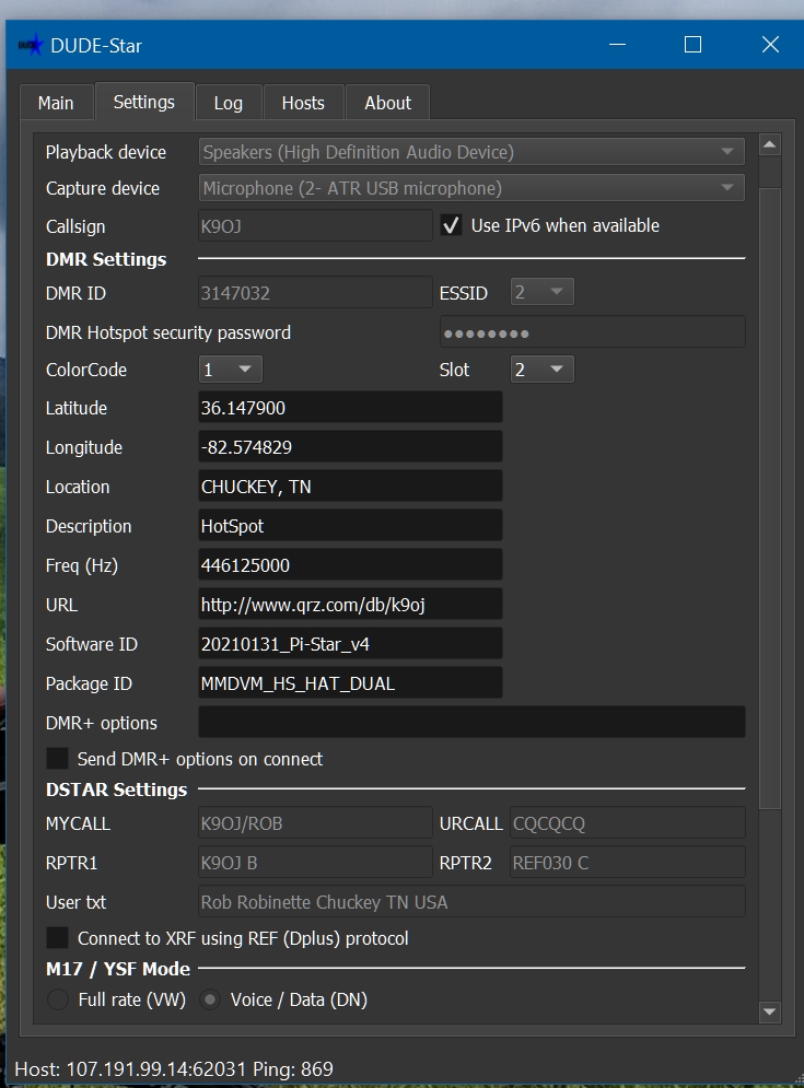
The "DMR Hotspot security password" is your Brandmeister DMR hotspot password (not your Brandmeister login password). The ESSID is the "02" appended to the DMR ID which should be unique. I use 01 for my Brandmeister hotspot and 02 for DroidStar. ColorCode should normally be 1 and "Slot" is the DMR Timeslot, 1 or 2. The Latitude, Longitude and Location should exactly match your Brandmeister settings. The settings tab will also get you going on D-STAR. The "RPTR2" box can be left blank because it is filled in automatically by the software. I changed the "Package ID" to MMDVM_HS_HAT_DUAL to keep Brandmeister from blocking DroidStar transmissions (matches my hotspot type).
Operating on DMR
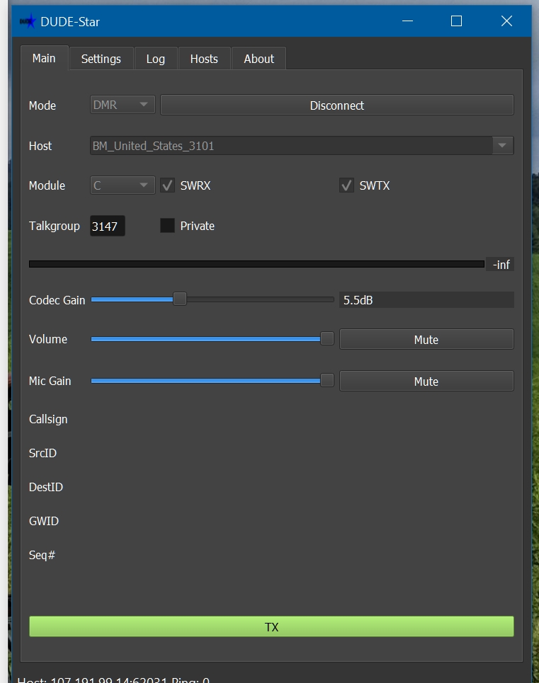
Just like with a DMR radio you have to briefly transmit to actually connect to a Talkgroup. Click the "Connect" button and then click the TX button at the bottom then click again to stop transmitting to connect to a DMR talkgroup. Above I'm connected and monitoring Talkgroup 3147 (Tennessee). Connect to Talkgroup 9990 and click Private for "parrot" to verify DroidStar is working and to check DroidStar's "Mic Gain" level. Whatever you transmit to the parrot Talkgroup will be repeated back to you. The BM_United_States_3101 host seems to have been taken down but BM_United_States_3102 works just fine with DroidStar.
To use DroidStar enter your settings on the Settings tab then on the Main tab select the Mode, Host (drop-down menu), select software receive and transmit "SWRX" and "SWTX" unless you have a hardware vocoder. For DMR and P25 enter the Talkgroup and click "Connect". To transmit click the "TX" button at the bottom of the screen. Click it again to stop transmitting.
Operating On D-STAR Reflector
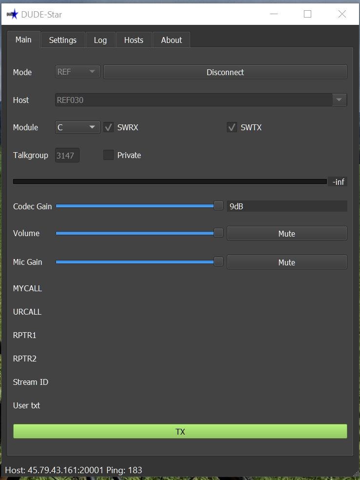
Mode is REF (D-STAR Reflector), Host REF030, Module C. "Talkgroup" and "Private" are not used for D-Star.
Main Tab For Working M17
Mode is "M17", reflector is "M17-M17", the module is "C" and the CAN (Channel Access Number) is 0. The M17-M17 module C reflector is one of the more active reflectors. You will find most of the M17 developers monitor it. CAN is normally set to 0.
Search for "DroidStar" at the Google Play Store to download DroidStar for your Android phone. New Releases of DroidStar for Windows, and Linux can be downloaded with a software vocoder installed and ready to go.
I want to give a shout-out to the DroidStar creator, Doug McLain AD8DP, for creating this very cool and free software.
Hammarlund HQ-One Eighty Tube Receiver
This is my only piece of tube ham gear and I absolutely love it.
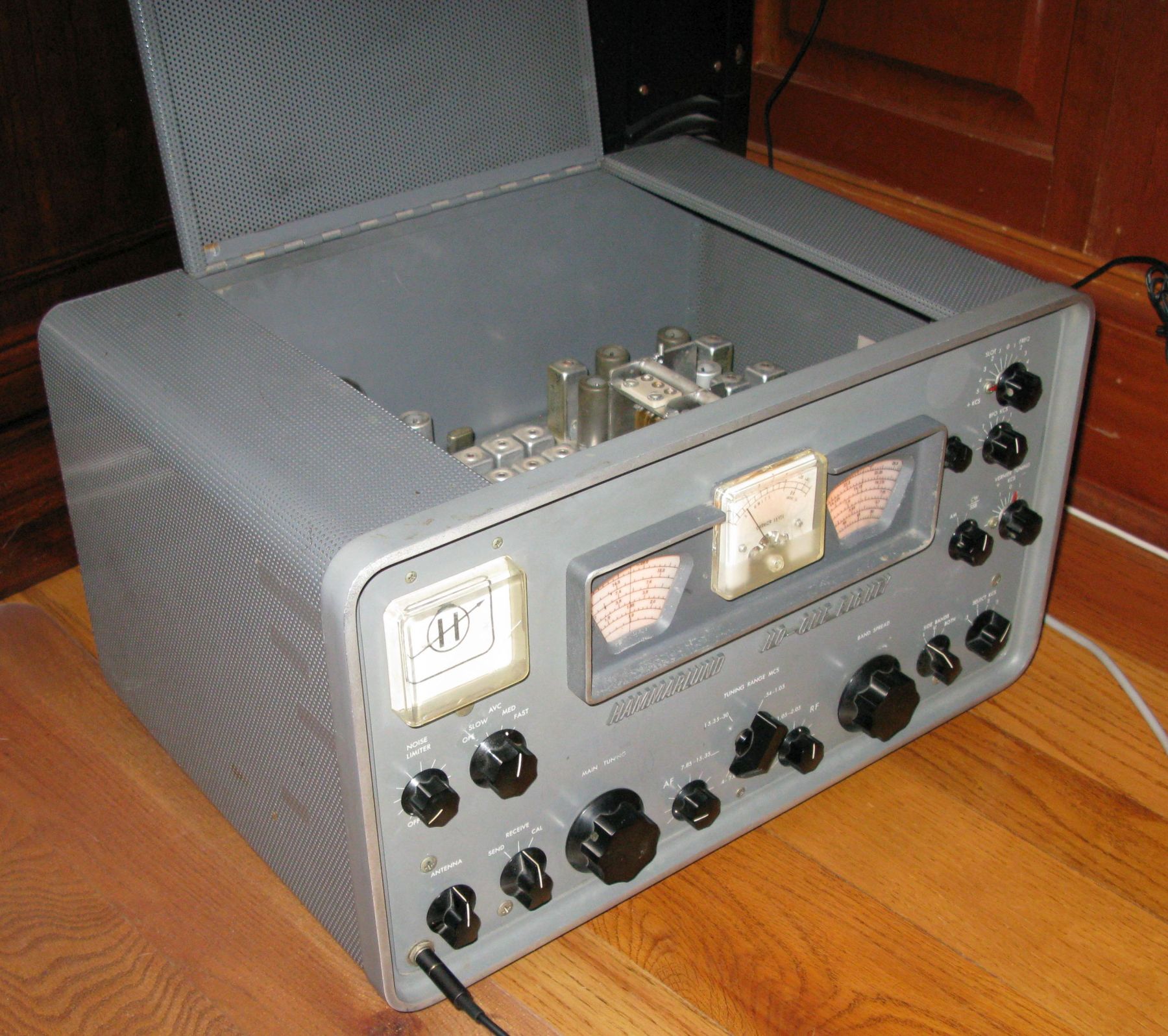
MFJ-1278 to TNC-2 Modification
Have an old MFJ-1278 modem lying around? See this to turn it into a stand-alone TNC-2 modem and APRS digipeater.
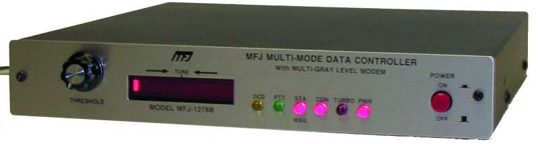
Mini Cooper Ham Radio and Antenna Install

Current QSL Card
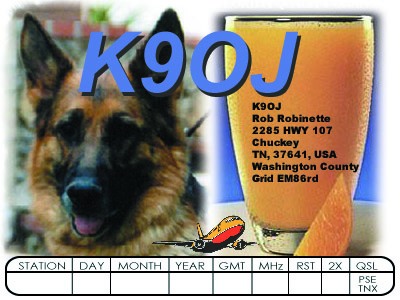
Old QSL Card
I piloted the C-141 for two tours. It had two 400 watt HF transceivers, two auto-tuners and one antenna so we had "dual watch" but could only transmit on one radio at a time. The tuners were in a pressurized 7psi container to prevent arcing at high altitude (very low air pressure). The antenna is the "bullet nose spike" on the T-tail. Here's an Avaition Radio Fundamentals presentation I used to teach C-141 pilots about their plane's radios. We had pretty good reception at forty thousand feet.
MajorValve says watch yourself inside that tube chassis.

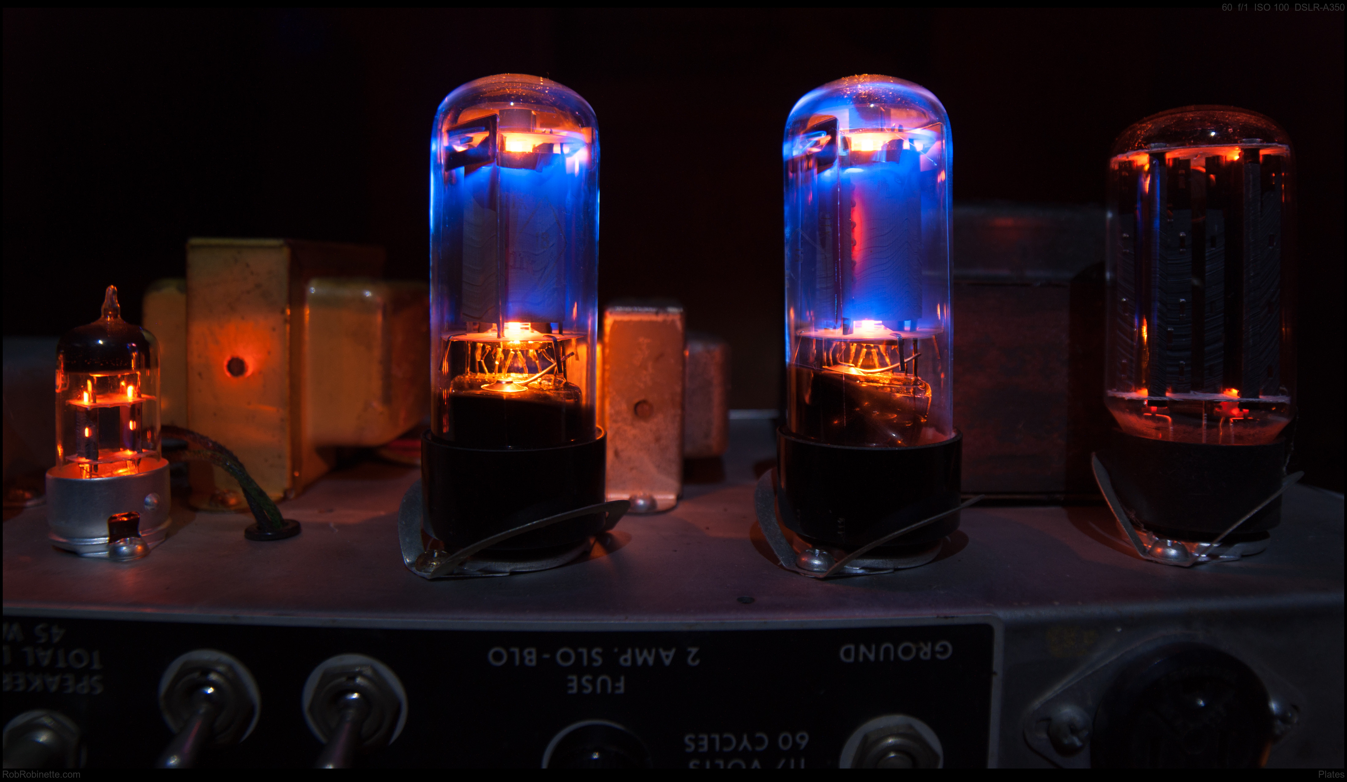
Comments and corrections are always welcome at robinette at comcast dot net.
[ How to MFJ ] [ How Tube Amps Work ] [ How the 5E3 Deluxe Works ] [ 5E3 Deluxe Mods ] [ Deluxe Models ] [ Amp Troubleshooting ] [ 5F6A Bassman Mods and Info ] [ How the AB763 Deluxe Reverb Works ] [ AB763 Mods ] [ DRRI & 68 CDR Mods ] [ Tube Bias Calculator ] [ Overdrive ] [ Deluxe Micro Amp ] [ Bassman Micro Amp ] [ Champ Micro Amp ] [ My 5E3 Build ] [ Reverb & Tremolo ] [ SixShooter ] [ Spice Analysis ] [ VHT Special 6 Ultra Mods ] [ Telecaster Mods ] [ Android Tube Bias Calculator App ] [ The Trainwreck Pages ] [ Fender Input Jacks ] [ B9A Prototype Board ]